The Design and Analysis of Tension Fabric Structures
by
Miriam Euni Son
B.S. Civil & Environmental Engineering University of California, Berkeley, 2004
SUBMITTED TO THE DEPARTMENT OF CIVIL AND ENVIRONMENTAL ENGINEERING IN PARTIAL FULFILLMENT OF THE REQUIREMENTS FOR THE
DEGREE OF
MASTER OF ENGINEERING IN CIVIL AND ENVIRONMENTAL ENGINEERING
AT THE
MASSACHUSETTS INSTITUTE OF TECHNOLOGY JUNE 2007
©2007 Miriam Euni Son. All rights reserved The author hereby grants to MIT permission to reproduce
and to distribute publicly paper and electronic copies of this thesis document in whole or in part
in any medium now known or hereafter created.
Signature of the author
--L
Department of Civil&
Environmental Engineering May 18, 2007Certified by
Jerome J. Connor Professor 7fCivil & Environmental Engineering Thesis Supervisor
Accepted by
Daniele Veneziano Chairman, Department Committee for Graduate Studies
MASSACHUSETTS INSTITUTE OF TECHNOLOGY
JUN 0
7
2007
The Design and Analysis of Tension Fabric Structures
by
Miriam Euni Son
Submitted to the Department of Civil and Environmental Engineering On May 18, 2007, in Partial Fulfillment of the
Requirements for the Degree of Master of Engineering in Civil and Environmental Engineering
ABSTRACT
Although tensioned fabric structures are increasingly in demand, since they are comparatively new to the engineering world, there are relatively limited resources available about such structures. This report reviews the topics that encompass the design and analysis of tensioned fabric structures. First, an overview of the conceptual basis of tensioned membranes is discussed, as well as the different shapes that are formed using manipulations of the basic concept. Since the material properties play a key role in the durability of tension fabric structures, the ideal material characteristics, as well as the current available fabrics are described. Both the strength of the employed materials and the load considerations for design are outlined. The report follows by explaining the process of roughly assessing the scope of a project, as well as the variety of non-linear analysis that must be performed and the methods used to perform them. This report concludes with key connection details that must be considered for a successful tension fabric structure.
Thesis Supervisor: Jerome J. Connor
I TABLE OF CONTENTS
INTR O D UC TIO N ... 5
S CON CEPT AN D FORM ... 6
1.1 Conceptual D evelopment... ... ... 6
1.2 Surface Types... 7
2. M EM BRAN E TY PES ... 9
2.1 Arch-Supported Structures ... 9
2.2 Structures with Primary Supports... 11
2.3 Ridge-and- Valley Structures... 12
2.4 M ast Structures... 13 3. M ATERIA L CH ARACTERISTICS... 14 3.1 Weave Patterns ... 14 3.2 M em brane Criteria ... 16 3.2.1 M echanical properties ... 16 3.2.2 Durabilitty ... 16
3.2.3 Light transm ission ... 17
3.2.4 Fire resistance... 17
3.2.5 Other m embrane criteria... 17
3.3 Fabric T pes... 17
3.3.1 Polyvinylcholoride (PVC) -coated polyester fabric... 18
3.3.2 Polytetrafluorethylene (PTFE)- coated fiberglass ... 19
3.3.3 Ethylene-tetra-fluorethylene (ETFE) film ... 20
TABLE 1 B: CHART OF FABRIC SPECIFICATIONS (CONTINUED) ... 22
4. D ESIGN AN A LY SIS ... 26
4.1 Load Considerations... 26
4.2 Physical M odels... 27
4.3 Two-D im ensional Prelim inary Analysis ... 28
4.4 Types ofAnalysis ... 30
4.4.1 Form finding... 31
4.4.2 Load and load carrying behavior... 32
4.4.3 Patterning geometry ... 34
4.4.4 Construction sequencing ... 35
4.5 Analysis M ethods... 35
4.5.1 M atrix method... 36
4.5.2 Force Density method ... 36
4.5.3 Dynam ic Relaxation vector-based method... 37
4.6 D esign Analysis Apiproach and Strategies ... 38
5.1 Fabric Connections ... 40
5.1.1 Fabric ioints ... 40
5.1.2 Curved membrane end-connections ... 40
5.1.3 Supporting structure end-connections ... 41
5.1.4 Com er end- connections ... 41
5.2 Cable Connections ... 42
5.2.1 Cable to support connections ... 42
5.2.2 Cable saddle connections ... 44
5.3 Pretensioni ... 45
5.3.1 Direct tensioning ... 45
5.3.2 Cable tensioning ... 45
5.3.3 Support structure tensioning ... 46
CO NC LUSIO N ... 47
INTRODUCTION
Fabric structures have been in existence for thousands of years. However, only in the last fifty years have these "tents" evolved into structures utilizing the inherent structural characteristics of the membrane. While tensioned fabric structures are fascinating to engineers for realizing materials to their fullest potential, they never cease to amaze the architect in its free flowing shape and design.
However, due to the nature of membrane structures, a conventional method of design and analysis does not suffice. Moreover, having a short history of half a century, relatively little information is available compared to conventional structures. Everything from the material selection, load considerations to the analysis method and the structural connections must be designed for the specific needs of the tensioned membrane structures.
In order to get a complete understanding of the aspects of design and analysis of tensioned membrane structures, not only do the conceptual basis and non-linear behavior
of the structure have to be understood, but the material properties and connection detailing between the different elements should also be considered as well.
1. CONCEPT AND FORM
1.1 Conceptual Development
The use of material is inefficient in bending elements. The interior fibers never reach
QI2IIIETI
/ /
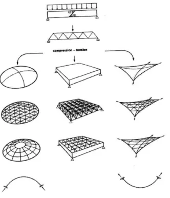
Figure 1: The conceptual development and effectiveness of tensioned membrane structures (Koch et al., 2004)
their maximum stress levels, while always maintaining weight. From this idea, the truss was developed where the inefficient material of the beam was turned into clear space and each truss carried specific tension and compression forces. However, the most simplest efficient structural system is when load is carried by one element that is either completely in tension or compression. While in two-dimensions, this system is a cable for tension loads and an arch for compression loads, in three-dimensional space, this system is a
dome and tensioned fabric,
respectively. This development is outlined in Figure 1. Therefore, terms "membrane structure" and "tensioned fabric structure" not only allude to the nature of the material used in such design, but also the way in which the forces act within the system.
The stresses created are membrane stresses, that is, stresses acting parallel to the local surface and constant through the thickness of the surface. Unloaded, the surface
prestresses are all in equilibrium. However, when the membrane is loaded, since it can not carry any out of plane stresses, it deforms until all the surface forces find a new equilibrium. Pretensioning of the membrane is necessary to decrease potential deflection. On a loaded pretensioned membrane, the final deflection will be less than a non-tensioned membrane. However, at the same time, the final tension will be higher.
The primary structure, which is usually made up of compression elements, play an important role for it equalizes and maintains forces from the prestressing of the fabric. Not only do they transmit the loads to the ground, but the supporting structure ultimately controls the geometric parameters of the structure.
1.2 Surface Types
negative surface curvature
positive surface curvature
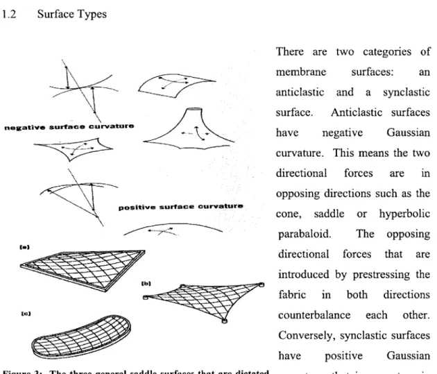
Figure 3: The three general saddle surfaces that are dictated by its linear (a), catenary (b) or curving boundary (c) (Huntington, 2004)
There are two categories of
membrane surfaces: an
anticlastic and a synclastic surface. Anticlastic surfaces
have negative Gaussian
curvature. This means the two directional forces are in opposing directions such as the cone, saddle or hyperbolic parabaloid. The opposing directional forces that are introduced by prestressing the fabric in both directions counterbalance each other. Conversely, synclastic surfaces
have positive Gaussian
curvature, that is, curvature in the same direction, such the
dome. Since the forces are in the same orientation, these forces must be balanced by air pressure. Tensioned fabric structures with anticlastic membrane surfaces will be
discussed hereon.
The anticlastic surfaces are also known as saddle surfaces. There are three general types of saddle surfaces. The surfaces are differentiated by their boundaries: linear, catenary or curving, as demonstrated in Figure 3. A combination of saddles made up of different boundaries result in the variety of membrane forms.
2. MEMBRANE TYPES
Membrane structures, encompassing both the tensioned fabric and the supporting structure, can span from 3 to 20 meters to spans more than 200 meters. For spans more than 200 meters, the fabric is supported by cables with steel or air so that unsupported span of the fabric is actually less than 30 meters. There are several systems adopted for tensioned fabric systems. While maintaining the concept of tension fabric design, each system is unique. These systems can be combined with each other to create interesting and even more complex designs. In this section, systems designed for anticlastic-surfaced membranes will be discussed.
2.1 Arch-Supported Structures
The arch-supported membrane shape is comprised of a saddle with one curving boundary and three curving boundaries as seen in Figure 4. This configuration is conceptually very pleasing since the membrane working in complete tension while the arch is ideally working in complete compression. These systems can be designed quite efficiently for
spans of about 25 feet.
The interaction between the membrane and the arch, which create the saddle curvature of the fabric, allows adequate resistance against buckling for shorter span arches. In order to achieve this, the arch must be relatively stiff. Using
Figure 4: Arch-supported structures composed tubular steel members with low bending
of a saddle with one curving boundary and three
stiffness is necessary. Other factors,
straight boundaries (Huntington, 2004)
such as the cross-section of the tubular steel members, the structural geometry and the properties and prestressing of the membrane can highly influence the degree of successful interaction and transmission of loads between the tensioned membrane and the
Figure 5: The stabilizing forces of an arch support structure (Koch et al., 2004)
supporting structure in compression. Additionally, keeping the warped (stiffer) direction of the membrane at right angles to the arch and designing for hinged arch supports is essential in this design. A successful design of the membrane and arch structure will result in forces as shown in Figure 5 that will stabilize the arch.
For longer spans, the stabilization that
occurs between the two systems is not
sufficient. Therefore, arches must increase in rigidity-this is usually carried out by
designing multi-chord truss elements.
While this increases flexural rigidity, the
connection to the ground is hinged so that minor differences with the loading of the arch
do
not
give
way
undesired reaction forces.
to
There
are
certain
disadvantages
of larger
scale arched roof systems
since, for various reasons,
the ideal, or catenary, shape
can not be realized. First,
when form finding, live
loads, such as snow and
wind loads, that do not
always exist are taken into
account with the loads from
pre-tensioning
and dead
loads.
Also, asymmetric
loading that occurs with
,~
7-~ ~r
Figure 6: Variations of arch structures studied by Frei Otto
(Roland, 1970)
...
snow and wind induces bending stresses on the arch. Second, the stabilization of the arched roof is essential and, at times, quite difficult. However, as discussed earlier, the membrane can assist in stabilizing the arch. Therefore, the base can and should be connected as a hinge to avoid high reaction forces at the base that can damage the structure.
2.2 Structures with Primary Supports
Saddle surfaces can also be created in the membrane by primary point supports that, unlike the arch-supported system, do not lie on the same plane. Care must be taken that the cable stays are in tension regardless the loading.
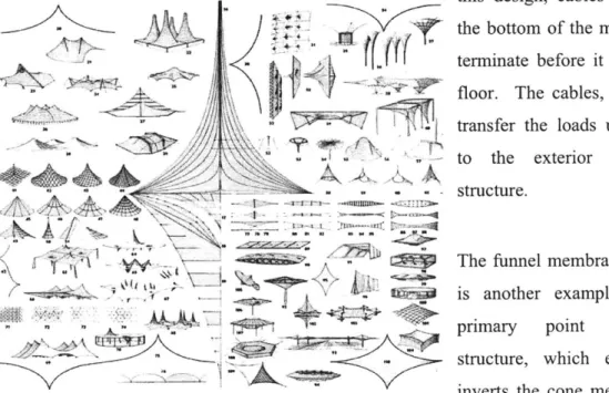
An example of primary point support structures is the simple cone structure that consists of a mast in the center of the membrane. This can be repeated in groups to enclose a larger area of space. Although this can fulfill many applications and provide the greatest range of shapes, the existence of a big structural element in the center of the utilized area can become awkward and obstructive. One solution to this is the king post design. In this design, cables support
the bottom of the mast that
- terminate before it hits the
floor. The cables, in turn,
V transfer the loads upwards
- to the exterior of the
- - - structure.
4-1
Figure 7: Variation of primary support structures studied by Frei Otto (Roland, 1970)
The funnel membrane form is another example of a primary point support structure, which essential inverts the cone membrane
-~ U .-=---'-*--- -. - --- - -~ - - -
-form. The high points take on the downward forces and the low points take on the upward forces.
There are key issues to consider when designing this structural system. One, the influences the membrane has on the lateral stability should be reviewed in order to design for any additional needed load bearing support structures. Different loading, especially asymmetric loading, and failure scenarios should be analyzed.
2.3 Ridge-and-Valley Structures
The concept of ridge-and-valley structures are based on the creating of slight saddle by laying cables in an adjacent pattern with opposing curvature. The membrane is created and restrained by the alternating ridge and valley cables.
IT
r
Figure 8: Variations of ridge-and-valley structure studied by Frei Otto (Roland, 1970)
The curvature created is quite small and therefore
this type of structure cannot be realized in all situations. Many tests and loading scenarios must be reviewed before deciding the feasibility of this kind of design.
2.4 Mast Structures
In tensioned fabric structures where the supporting structure consists of masts, fabric is suspended from cables hung off masts or other compression elements. This kind of system is ideal for long span roofs. There are many forms of mast structures. The main three forms are the following: masts with hinged supports stabilized with cable stays, masts with hinged supports stabilized by the membrane and masts with fixed supports.
The masts must support both axial loading and lateral wind and dead loads (for angled masts). To resist buckling, which the masts are highly susceptible as a result of the axial forces increasing Figure 9: A mast support structure the moment stresses, the masts are constructed in (Koch et al., 2004) lattices. The hinged base must be able to initially roll when the masts rotate, but after 2 degrees of rotation, the hinge must be able to slide. Care must be taken through construction and materials to ensure that excess friction does not impede this action.
In order to prevent domino effect-like failures, analytical techniques should be employed. Testing of full scale modules can also be used to confirm the safety of such
structure.
An example of a mast system is the Millennium Dome in Greenwich, England which covers 80,000 square meters. It is a single module made up of 12 trussed steel masts from which cables support 72 radial cables lines. Stabilizing
cables were attached to the membrane and low points of the Figure 10: Masts of the mast to resist wind and uplift forces. Millennium Dome (Koch et
3. MATERIAL CHARACTERISTICS
The selection of membrane material is important to the successful design of the tensioned fabric structure. The material contributes to the structural function of the system, as well as other important properties involving durability, insulation, light transmission and fire protection. Also, the membrane component of the structure determines the long term appearance of the structure for it is the most visible element of the structure.
Currently, glass and polyester laminates, composites and fluoroplastic films are most popular. When selecting a membrane, the most important qualities to consider are the mechanical tensile strength and the elastic properties. Due to this, 90% of all weather-proof tensile fabric structure projects have used the following three specific membrane
materials: Polytetrafluorethylene (PTFE), polyvinylcholoride (PVC) and
ethylenetetrafluorethylene (ETFE) (Huntington, 2004). These materials are preferable in tensile fabric structures for an array of reasons. Not only do they have the structural ability to support such structures, these materials have been in use for the past 50 years and therefore behavior data of these materials are abundant. These materials have become standardized and therefore the ease of acquiring and designing for these materials are higher than others.
3.1 Weave Patterns
The membrane is made up of yams that are in turn made up of fibers. These fibers, which are generally made of nylon, polyester, glass and aramids, compose the structural component of the membrane. Since single fibers can not sustain themselves as a 14
membrane, many fibers are either twisted together or are brought together in parallel. The different fabrication methods of these yams play a significant role in the ability to extend and bend.
The yam is then either woven or laid on top of each other to create a fabric. The different kinds of arrangements of the yam are show in Figure 11. In the plain weave, the warp direction of the yam is laid taut while the fill direction weaves in and out of the yam in the warp direction. In the laid weave, the yams are simply placed on top of each other in a perpendicular fashion. Due to the nature of these two weaves, the plain weave fabric is about three yam thicknesses, while the laid weave fabric is only two. The warp and fill directions of the plain weave fabric will exhibit different strength values in the two directions, while the strength will be roughly the same in the two directions for laid weave fabrics. The variation in the twisting of the yam and the different strengths of the
Figure 11: The loose plain warp and fill directions result in different behavior under weave, tight plain weave load. Twisted yams are more flexible and extendable that
and laid weave of yams that are not. Also, the warp direction of the fabric
membrane yarns (Shaeffer, will stretch under load, while the fill direction will
1996) straighten. Therefore, great understanding is needed on the
type of fabric being used when designing and analyzing
different load behaviors.
For plain weave fabrics, an exchange between the two directional yams called "crimp interchange" must occur before the fabric can start carrying load. This is when the fill direction straightens out and transfers some of its curvature to the yams in the warp direction. The negative side to crimp interchange is that the fill direction loses some of its pretensioning in "filling" out its curves. Also, no computer analysis program is able to model the fabric to reflect this interchange in the analysis of the structure.
3.2 Membrane Criteria
There are several parameters to consider when selecting the type of membrane fabric to employ. Of these, the most important are the mechanical properties, durability, light transmission, fire resistance and economic feasibility. For common materials used in practice, such as PTFE and PVC, material behaviors and characteristics have been well recorded. However, for newer materials and innovative applications, there are a wide range of tests that can be performed to get an idea of the properties and qualities of the material.
3.2.1 Mechanical properties
The mechanical properties of most importance to the designer are the tensile strength, which measures the force required to rupture the material, tear strength, which is the resistance to propagate an existing tear, and elastic properties, such as stiffness, which is the relationship between the modulus of elasticity and the area of the cross section of fibers. These properties are measured through a number of tests including, but not limited to the Strip Tensile, Grab Tensile, Biaxial Tensile, Seam Tensile Strength, Trapezoidal Tear, Tongue Tear, Adhesion and the Abrasion Resistance Test.
3.2.2 Durability
The life span of the membrane structure strongly depends on the durability of the membrane fabric. Its durability is greatly influenced by the resistance to degrading from UV radiation and wicking, attacks from organic matter, and the maintaining of seam strength. Vandalism and soiling can also affect the durability of the membrane. For newer materials, the durability can be tested by accelerated weather tests using different environmental conditions, and stain resistance/ clean-ability tests.
3.2.3 Light transmission
When designing a tensioned fabric structure, great consideration is given to the light transmission, absorption and reflection of the structure. This will ultimately affect the appearance and some aspects of the energy behavior of the structure.
3.2.4 Fire resistance
Fire resistance is also an extremely important factor for safety. All materials are required to undergo the following standard fire tests: ASTM E84 Surface Burning Characteristics of Building Materials (Flame Spread Test), ASTM E108 Fire Tests of Roof Coverings (burning brand, spread of flame, intermittent flame exposure, flying brand or rain test),
ASTM E136 Behavior of Materials in a Vertical Tube Furnace at 750C (ASTM 1999a) and NFPA 701 Fire Tests for Flame-Resistant Textiles and Films (NFPA 1999).
There are many other criteria that is looked at before making a decision of the material to be used.
3.2.5 Other membrane criteria
While the importance of certain qualities and characteristics depend on the scale and design of individual structures, the above qualities are the characteristics that play an important role in all membrane structures. Other characteristics include the following:
3.3 Fabric Types
The oldest and most commonly used fabrics are coatings or laminates over polyester fabric. Different kinds of coatings are employed for different desired characteristics. For example, neoprene and hypalon are used when opaqueness is desired and reapplying
coats are expected. Urethane coating is used for fabric that will be repeated folded in cold temperatures to prevent cold cracking.
3.3.1 Polyvinylcholoride (PVC) - coated polyester fabric
Polyvinylcholoride (PVC) coated polyester fabrics have been used and tested since the 1960's. The wide use of this material is due to their low cost, as well as their ease of handle. However, their life expectancy is only 10-15 years and fire ratings can be improved. The PVC coated polyester has tensile strength from 350 MPa to 1,200 MPa and a strip tensile strength of 3,100 N/5cm to 5,800 N/5cm for membranes weighing 800 g/m2 to 1,100 g/m2 (Huntington, 2007). The prestress levels of PVC coated polyester fabric range from 1-4 kN per meter (Shaeffer, 1996). The PVC coating helps the material to achieve high tear strength for the soft PVC chains around the fibers at the tear to resist further tearing. PVC also has moderate stiffness as well as moderate behavior to creep. Although this at times requires pretensioning of the fabric, the moderate behavior to creep allows for some flexibility in matching fabricated components and small errors in fabrication will not result in overstress or wrinkles in the fabric.
PVC-coating protects the fabric from UV radiation degradation for roughly 10 to 15 years (Huntington, 2004). Although additional top coats to protect from UV radiation can prolong the life span of the fabric, it is not very effective. PVC coated polyester can achieve light translucency of up to 22 percent and although this fabric is not deemed incombustible, it is classified as a flame retardant. Due to the fact that high temperatures create holes in the material that allow the smoke and heat to dissipate through the membrane, its incombustible nature can add to the overall safety of the structure in a fire hazard.
The most appealing characteristic of PVC coated polyester fabrics is the low cost. In 2003, the cost of this material ranges from $90 to $150/m2. This calculates to $400 to $700/m2 for a complete PVC coated polyester roof structure (Huntington, 2004).
3.3.2 Polytetrafluorethylene (PTFE)- coatedfiberglass
Another type of membrane fabric commonly used in practice is Polytetrafluorethylene (PTFE)-coated fiberglass. This material was developed in 1969 when fiberglass fabric was coated with Teflon resin. This new material advancement was a landmark in time for tension fabric structures for it was incombustible, resisted soiling and promised a more durable and therefore longer life span to membrane structures. However, this material was very expensive and had a low resistance to cracking compared to PVC-coated polyester fabric. Therefore, PTFE-PVC-coated fiberglass became the material to use in long-lasting iconic architectural applications, while PVC-coated polyester fabric continued to be used for temporary, portable structures that can withstand the effects of being repeatedly erected.
The mechanical properties of PTFE coated fiberglass is 3,500 MPa and the strip tensile strength range from 1,600 N/5cm to 8,800 N/5cm. These strengths allow membranes to stretch long spans with minimal curvature. However, the tear strength of PTFE-coated fiberglass is relatively low, having only 80 N to 550 N of strength to resist tears from propagating. The prestress levels range from 6-8 kN/m, 4-6 kN/m and 1-2 kN/m for heavy, light and light lining PTFE coated fiberglass fabrics, respectively (Shaeffer,
1996).
Case studies have proved that PTFE-coated fiberglass fabric has a expected life span of over 30 years. Structures, inspected at 30 years of age have no need of replacement due to wear and degradation. The several coats of PTFE make the fabric nearly unsusceptible to any damage due to UV radiation as well as chemical attack and wide temperature variation. In one case study of the La Verne structure erected in 1973, pre-stress levels of the fabric remained relatively uniform and near the original levels after 6 years (Huntington, 2004). This shows that the fabric does not creep and distort over time. In fact, the creep was measured to be only a third of its PVC-coated polyester fabric counterpart. However, there are negative aspects of this material. Since PTFE-coated fiberglass fabric have low tear strength, its vulnerability to tears and rips due to vandalism and structural overloading increases substantially. Also, fiberglass is
vulnerable to wicking from edges exposed to water. However, this can be mitigated by water-repellent coating. The cost of PTFE-coated fiberglass fabric is quite expensive. For the full fabrication of a tensioned fabric structured roof using PTFE-coated fiberglass fabric, the cost ranges from $500 to $1,000/m2-five to ten times as much as PVC-coated polyester fabric.
3.3.3 Ethylene-tetra-fluorethylene (ETFE) film
Films are also used to make up a membrane fabric. In actuality, although the films do not depend on any property of the woven fabric in the middle, without it, it can not be considered a fabric. One commonly used film is ethylene-tetra-fluoroethylene polymer (ETFE). The tensile strength of 0.1mm thick film is 225 N/5cm-only 5% of PVC and PTFE-coated fabrics. These films continue to creep under load, unlike the PTFE-coated fiberglass fabric. The film yields after elongating 3% and ruptures at 200% of its original length (Huntington, 2004). This behavior gives ETFE film very high tear strength. It is possible to use composite woven fabric in between the film to increase the overall tensile strength.
Although there are limited tests, films, which exclude the performance of the woven centers, can be expected to endure 15 years facing the environmental elements. However, the durability, as well as the light transmission, fire resistance and cost, all depend greatly on the scale and design of the material and structure.
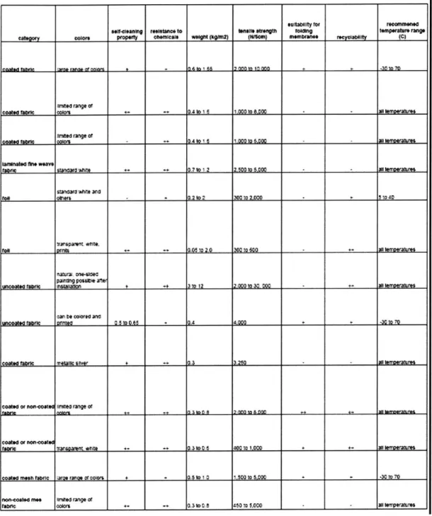
Table la and Table lb on the following page is a chart of detailed fabric specifications.
0 e 46 aa A A A A l4 4~~~4 t2JA
~'
1+ Cu C Cu Cu Cz
Cu Q Cu CuTable 1b: Chart of fabric specifications (continued)
sutabolty mr r*ComMnend
seVet.enbg rew.tai"c. to afstfs St"Wigth 0ftng tmpvrt ring.
""otor property OaenM'cu. woi.t(om (MU" auOkn.. fec3"t(
filtid raig. or
cotd grc colors e- - 04 to 6 10O to &O00 - l eprbt .
a.d Aings of
COONO ftbrt cOwmr m- +1A o s tC40 to &Mco 2H kffOwrbff
iamngsd Io. Weave
662Wt fawk ar WWIi DA to1.5 1 =00 SAM 300 mw neaun
am '1*f -07*J1 -I L ltand" rwtift &-4
100 oihers - - .2to2 3M Wl 20=j *
tr#aeWet weM,
fon~
~
UV~t "Iftm2 30 60mnereW.* ,E E _
~
- ''L ;Mnam one-so
Uncosw tbf =Polo* 3s10n~ + ++10M tc to Xo Mo ++ aywem
aw t* QOwsd ar
Unfooledawr e _ 0_ 5 o GAS + A A-000 - M0 70
99"Md eam Irlaum Owv + + 21C - - a22tmprm
"Sat" or AWVoaO nt led fxgw of
guam MUMa n 20 mn
l-e-c00tud of ftnCOSMos
fCASO mo b ranm or vot aSDI +I. 0 00 ta 7 0 J epeai
nontonie rmes WVNd fnge of
3.4 Cable Types
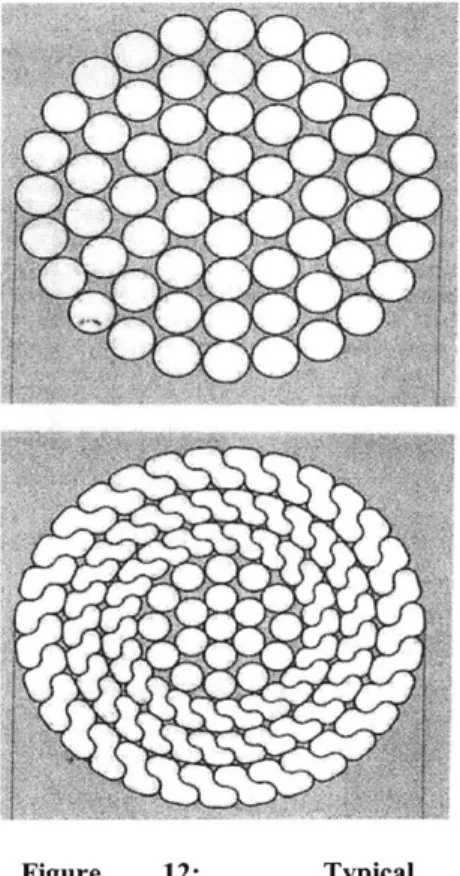
Other than the membrane fabric, the cables used in the structure must also be selected. The strength and durability, as well as the flexibility and bending radii play a key role in the selection process. In most cases, high-strength
steel wire is opted. Typically, 11 strands are wound together, each strand being made of up 19 to 37 wires wound together as shown in Figure 12. These high-strength steel wires are ideal because they have great flexibility while maintaining strength. Therefore, these wires can be used for membrane structures that are designed with tight radii. Steel structural strand is also another type of cables used when less flexibility is needed. While the strength of these cables is greater, the ability to bend is quite limited. Steel tension rods are used, while its usage is limited non-curved applications.
Corrosion has the greatest affect on the durability of
Figure 12: Typical
the cables. Protection from corrosion, as well as other configurations of a strand made staining, is usually provided by galvanizing the wire up of wires (Koch et al., 2004) with zinc coating. A more expensive option is to
employ stainless steel.
When selecting cables for a particular design, the following strength criteria should be used. The breaking strength of the cable should be the maximum value of the following:
a. 2.2 * Net tension due to dead load and prestress
b. 1.6* Net tension due to dead load and prestress + 2.7*Change in tension due to live load
c. 2.2*Net tension due to dead, live load and prestress
d. 2.0*Net tension due to prestress, dead, live, wind and earthquake load e. 2.0*Net tension in cable due during construction
f. 2.0*Net tension due to dead, wind load and prestress
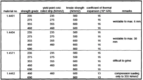
Cables should also be able to prestress at 4-10% of their breaking strength (Shaeffer, 1996). Table 1 and Table 2 on the following page outline the different strengths of cast steel and stainless steel.
Table 1: Strength of cast steel
Table 2: Strength of stainless steel
25
yield point cold- tensile strength coefficient of thermal
material no. strength grade rolled strip (N/mm2) (N/mm2) expansion (10A-6/K) remarks
1.4401 235 235 500 16 275 275 550 16 weldable to max. 6 mm 355 355 600 16 460 460 600 16 1.4404 235 235 500 16 weldable to max. 30 355 355 600 16 mm 460 460 600 16 690 800 16 1-4571 235 235 500 16 275 275 550 16 355 355 600 16 difficult to grind 460 460 600 16 690 800 16 1.4462 460 460 600 13 compression loading 690 800 13 only to 355 N/mm2
cast steel with enhanced high-strength cast steel welding properties and with good welding
materials impact resistance properties cast stainless steel
reference no. GS20 Mn 5 V GS18 NiMoCr 3 6 V G-X 5 CrNiMo 16 5 V
german standard DIN 17182 SEW 520 SEW 410
materiao no. 11.12 16.759 14.405 thickness (mm) <100 mm <160mm <80mm <150mm yield point (N/mm2) 300 280 700 630 540 tensile strength (N/mm2) 500-650 500-650 830-980 780-930 760 breaking elongation (%) 24 22 12 12 15
notched bar test min. 40 min. 40
4. DESIGN ANALYSIS
Like designing any innovative and high-precision structure, thorough analysis of the design must be carried out for tensioned fabric structures. Multiple load scenarios must be analyzed to ensure the structural integrity of the system in all situations. While all structural analysis is performed by computers, physical modeling and two-dimensional hand calculations are still employed to give a sense of possibilities and ideas. Non-linear form-finding and load analysis are imperative to conduct simultaneously as an integral part of the designing stage for a successful design of a tensioned fabric structure.
4.1 Load Considerations
Although ASCE has developed standards, loading standards for tensioned fabric structures fall under the specifications of building code requirements. This can be deceiving for these loads did not consider the deformability and flexibility of the membrane structure. However, a good understand of load considerations specifically for membrane structures can assist in the analysis.
Wind loads are the main consideration for membrane structures. In order to resist these loads, the membrane must have sufficient tensioning and curvature. While load coefficients are easily assessable in most places, other tests such as a wind tunnel test may be necessary for larger and more complex structures to determine loading distributions. The possibility of aeroelastic effects that occur when the structure is vibrated with its natural frequency must also be considered. This is especially true if the natural frequency of the structure is significantly longer than one second. In such cases, further investigation of the aerodynamic instabilities should be carried out by using models that reflect the real-life mass and flexibility parameters of the structure.
While wind is usually the most significant of loads for the membrane structure, in areas of colder climate, snow and snow drift loads can also be substantial. Again, while snow
load coefficients are available, physical model testing may be required for complex structures. Snow drift loads can be analyzed by the Finite Area Method, where the snow drift is modeled as a thin layer of particles moving with a mass flux related to the wind velocity.
Point loads should be avoided on the membrane component of the structural system. The necessary heavy point loads should be set on the supporting compression structure at all times possible.
There are several loads that are negligible in membrane design. The self-weight of the membrane is usually negligible, but often included in the analysis. Moreover, due to the negligible weight of the membrane, seismic loads are also usually insignificant and not incorporated in the analysis. Rain loads are also rarely considered since water will be designed to shed rapidly to avoid ponding. Live roof loads can also be significantly reduced for it usually accounts for building material during construction, which is irrelevant in the case of membrane structures. Lastly, as of yet, temperature gradients of the membrane have not produced accountable loads for the fabric.
Although there is no set safety factor for the strength of the selected fabric, conventional practice is to use a factor of 4 for short term load cases and a factor of 5 for live load cases (Huntington, 2004). In order to mitigate the fact that these factors do not take into consideration many imperative aspects, ASCE is currently developing a methodology obtaining more reliable safety factors.
4.2 Physical Models
In the early stages of tensioned fabric structure design, there was heavy dependence on physical models. These models consisted of soap film for minimal surface finding, wire and stretched fabric. Famous for such works is Frei Otto based in Germany who pioneered patterning and initial form data for later computer analysis. His greatest
innovation was in his work with soap models like the one shown in Figure 13. Soap bubbles stretch between supports and the final shape of a soap bubble is one having the least potential energy, minimizing the tension in the system. This is of particular interest for at this precise state, the tension stress is equal at every point of the bubble and the minimum surface area is found. Frei Otto correlated this to membrane structures and was able to find the most stable and uniformly pre-stressed form of a membrane between any set of arches and masts.
Although physical models are used for conceptual phases, especially at the initial designing stages for tensioned fabric structures, currently, form-finding, load behavior and patterning is undertaken by computer analysis. Additionally, the soap
bubble models use have uniform stress levels Figure 13: A soap arched membrane in both the warp and fill direction of the
membrane. Although this is highly reflective of nature and quite aesthetically satisfying, in practice, the warp and fill directions can have variable stresses, allowing for more variety and choices in the designing process.
4.3 Two-Dimensional Preliminary Analysis
Simple two-dimensional hand calculations, based on a few assumptions, can be performed to get an initial idea of scope and feasibility in the design stage. By using these calculations in critical locations of the structure, one can deduce the overall behavior of the structure. The cable follows the characters tics of a membrane, having no
compression, shear or bending and the tension forces must be balanced.
The following is an example of a simple analytical procedure using the idea of a uniformly loaded cable to obtain rough estimates of the reaction forces and end
The membrane under vertical load is approximated as a parabola, although circular arc approximations are also valid.
The original arc length of the cable in its catenary shape is:
A =2X(L L + 4h
2 )Y
A =2x~
+---+-4 3
The vertical reaction at the end of a cable under uniform live load is:
V wL 2
where w is the vertical load per unit length and
L is the length of the cable
The horizontal reaction force is:
H wL
8h
where h is the height of the sag
The force in the cable is:
F =(V
2 +H
2)The tension force can be approximated to equal H if the sag ratio (h/l) is 0.2 or less.
Under lateral loading, the tension in the cable is:
F WL2
+4h)
F = w +4
8h
where w is the lateral force per unit length
29
Now, the change of arc length under load is:
_ F x A
E
where E is the modulus of elasticity
Therefore, the new arc length is:
Knowing this, the updated sag of the membrane is:
h' - x VA'- L2 4
Using the value of h prime, and value for F, the tension of the cable should be updated. Several iterations are needed in order to converge to a relatively constant value. This is imperative since final results can greatly differ from results calculated after a single iteration.
Although this and other simple calculations were used from geometries from physical models, with the development and availability of analysis computer software, these calculations are used only at the conceptual stages to sense out initial design, feasibility and scope.
4.4 Types of Analysis
With the increasing of innovated materials and demand for more complex designs, it is even more imperative that thorough non-linear numerical analysis be conducted. Having low shear stiffness and no compression force carrying capabilities, the membrane carries load by making significantly large displacements and movements. This results in a unique non-linear behavior since the displacements are not proportional to the applied
loading. Thus, many iterations of analysis with updated stiffness values must be performed to get accurate results. Also, time sensitive scenarios, such as the membrane wrinkling or the cables relaxing must be assessed.
If the supporting structure is rigid, the primary and membrane structure can be analyzed separately, making non-linear analysis needed only for the membrane component of the structure. However, if the primary structure is flexible relative to the membrane structure, the entire structure should be analyzed together in a non-linear form. In this discussion, only the non-linear analysis for the membrane is considered.
In addition to analysis for form-finding and behavior under load, non-linear analysis is performed for material patterning and construction sequencing. Due to the importance of high-precision in the construction of such structures, accurate fabrication membranes for all materials must be provided through patterning by numerical analysis. Additionally, an analysis of the sequence of construction may be necessary to ensure that none of the components of the structure are overstressed during the construction phase.
4.4.1 Formfinding
Warp Fill stress ratio
1:1 2:1 3:1 4:1 51
T
Is
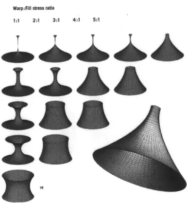
The ideal form of the tensioned membrane has uniformly or constant varying stresses in both the warp and fill directions of the fabric. The shape is directed and formed by both the geometry of the supporting structure and the prestress introduced to the membrane. Ultimately, the warp and fill directions of the fabric should coincide
31 Figure 14: Varying membrane forms resulting from
different preset stress values in the warp and fill directions and slightly altering geometries (Koch et al., 2004)
T
x1*
with the main curvature of the membrane to optimize the stiffness of the tensioned membrane.
With computer-run numerical processes, the given prestress values and geometry calculate the forces induced at each element. To assist in aligning warp and fill directions with the principle curvature, a line is super-positioned over the model to trace the shortest distance between boundaries. As the optimum shape is being found, by changing geometry and stress levels, the forces and shortest distance paths are continually updated. Of course, there are times when the given prestress values will not result in any feasible shape. It is also important to note that during this time, no material properties are taken into consideration.
The analysis of a simple conic shape in Figure 14 demonstrates the range of outcomes with varying structural geometries and preset stresses. As the upper ring is decreased, the allowed stress in the vertical direction must increase. If there is not enough allowed stress in that direction, the shape will be deemed unattainable, as portrayed in the top-left images of Error! Reference source not found.. When the upper ring of the same conic shape is replaced by a cable, the cable deforms to make up for the increased stress that is needed in the vertical direction.
4.4.2 Load and load carrying behavior
The non-linear behavior of the membrane under a variety of loads must be considered as well. As mentioned earlier, both the curvature and loading affects the stress on the membrane, as shown in the following equation:
stress = radius * load (all vectors)
Therefore, when loading is applied to the membrane, equilibrium is regained by changes in both the geometry of the membrane as well as the change in stress. Other structures, such as beams, have shear and flexural stiffness and therefore can resist the loads without significant deflection. However, membranes, which lack both shear and flexural stiffness, must "make up" for this
Down load by big deflections.
Furthermore, the stress levels
vary depending on the direction + ..
o, increases (sagging direction)
and position of the membrane. er
Wsts ch"Xge rovern" for An example of this can be 12Reduces (hogging direction) wind uplift
demonstrated by a membrane
Wind mnd snww ling applied
stretched across two masts with to cunt dehed lb- via
suembrane elemant surface
the warp direction between the
two points. Accordingly, the Figure 15: The change in stress in the sagging and warp direction has an upper hogging directions of a membrane under vertical
load
curvature and the fill direction (Koch et al., 2004)has a downward curvature. As shown in Figure 15, as the
downward load is increased, the stress in the warp direction is increased and the stress in the fill direction is decreased. Conversely, as an upward load is increased, the stress in warp direction is decreased and the stress in the fill direction is increased. 5 U
'I
m Figure 16: Analyzed membrane structure in Error! Reference source not found. (Koch et al., 2004)An iterative analysis between form finding and load carrying behavior is carried out to ensure that both structural (warp and fill stress ratios, geometries, strength) and logistical (adequate head room, avoidance of ponding, constructability, etc) issues are equally resolved. Table 1 shows a load case study of a membrane with different warp-to-fill stress ratios under varying loads. The search of finding a form with sustainable load carrying behavior is quite complex for every
33
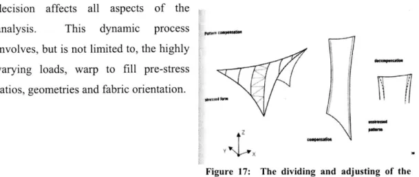
decision affects all aspects of the analysis. This dynamic process involves, but is not limited to, the highly varying loads, warp to fill pre-stress ratios, geometries and fabric orientation.
77""W
Figure 17: The dividing and adjusting of the
memhranp that are entailed in natternino (Knch
Table 1: Load case comparison of membrane shape in Error! Reference source not found. with varying warp-to-fill prestress ratios (Koch et al., 2004)
warp to fill direction max membrane stress under load
prestress ratio unloaded 1 kN/mA2 down 1 kN/mA2 up 2.1 kN/mA2 up
warp 1.0 9.0 3.4 5.8 fill 1.0 3.4 9.2 18.0 warp 2.0 11.8 4.7 8.1 fill 1.0 2.2 7.3 14.7 warp 3.0 13.6 5.4 9.1 fill 1.0 1.7 6.6 13.4 4.4.3 Patterning geometry
In order to fabricate the membrane, the membrane may be divided into triangular pieces from the two-dimensional area derived from "unfolding" the three-dimensional membrane model. The tracing of the geodesic seam lines must be an integral part of the form-finding and load behavior analysis to reach the optimal solution.
The difficulty lies in compensating for the final prestressed geometry when patterning. The final model represents the geometry of the membrane after it is pre-stressed and loaded and thus stretched. Therefore, when "unfolding" the membrane for fabrication patterning, the actual fabric will be slightly reduced, as illustrated in Figure 17. Biaxial testing on the material being used determines the elastic properties that are needed to calculate the compensation required.
4.4.4 Construction sequencing
41A ka
baw uibsP0,
Figure 18: The finite element make-up of the membrane (Koch et al., 2004)
At times, an in-dept analysis of construction sequencing should be considered. This is particular so when the supporting and membrane structure are not stable until the final stages of construction. These kinds of studies are
done by going backwards in the
construction sequence. Initially, the pre-tensioning of the membrane can be slowly reduced to see the non-linear behavior of the overall structure. Then, the different components of the structure can be deleted in the reverse order of construction.
4.5 Analysis Methods
The numerical analysis is done by the finite element method. The basic concept of finite element is to divide a model into a finite number of elements, made up of nodes. In the finite element method, the nodal stresses are calculated through equilibrium equations related to stiffness. Once the nodal deformations are obtained using the stress/strain relationships, compatibility is approximated for the entire structural model to a pre-set tolerance. This is a complex iterative process involving thousands of nodes and calculations, and at times, no solution can be found.
When using analytical computer programs, it is imperative that the engineers know and comprehend the method of analysis of the program and how the program operates. This includes knowing the algorithms implemented in the analysis, as well as how the program responds to inputs and the method of feedback. Understanding how the program reacts in
certain situations, such as local instability and infeasible geometry, is vital. Having a physical model to compare analytical results will help in examining the validity of the results.
The program selected to perform the analysis should also have full range of capabilities to alter the model in geometry, stress and load. This is particular imperative for the design phase of the structure. If there are limitations, having a clear understanding of them will be useful in evaluating the various responses of the program.
Although specialized programs are being created to address the analysis of membrane structures, none of the methods available take into consideration the fabric behavior of crimp interchange, which was discussed in an earlier. Conventionally, a value of the stiffness for both the warp and fill directions are used that approximate the average stiffness throughout the life of the membrane.
4.5.1 Matrix method
Programs that are designed specifically for the design and analysis of tensioned fabric structures are based on of two different finite element methods: the matrix method and the vector method. The matrix method uses the Newton-Raphson method where the tangential stiffness of the entire model is incrementally solved to a convergence point.
4.5.2 Force Density method
A method called the Force Density method is implemented in the form finding segment of the analysis. This method is particularly attractive because it is a linear method. In the
[b]
1d]
*
[a]
[ci
Figure 19: The concept behind the Force Density method (Huntington, 2004)
However, this is resolved by applying a consta
Force Density method, the stiffness of membrane strips is modeled as a grid of cables (Figure 19a). Using linear methods, the shape that
0 stores the least total potential
energy and uses the minimum length of cables is found. Since linear methods are used, the shape is quite irregular and extreme, modeling some cables with infinite stiffness (Figure 19 b and c). nt force density to the entire model, resulting in a shape between the extremities (Error! Reference source not found.d). This method was later updated to use triangular surface methods, rather than cables and is know as the Surface Stress Density method. The weakness of these methods is that the final stress distribution is not very smooth and thus sometimes difficult to replicate in practice. Although this can be mitigated by carrying out multiple iterations, the method
ceases to be a simple linear analysis.
4.5.3 Dynamic Relaxation vector-based method
Vector methods are more popularly used than matrix methods for membrane form finding and load analysis. Vector methods keep the equilibrium and compatibility relationship separate a convergence point is met with the equilibrium equations. The nodal stiffness is also not integrated with each other until the end of the process.
The vector-based Dynamic Relaxation method is the most widely accepted method used today. In this method, the form-finding and load analysis are solved using dynamic analysis methods, which involve mass and damping coefficients and time steps. At each time-step, the forces at each node of the finite element model are calculated. The net 37
forces in the model are then attributed to the acceleration of the model at that time-step. As the model comes to rest, the forces causing the acceleration will shape the surface of the prestressed equilibrium state at that increment. This method is popular for its ease of use and capability to analyze successfully the great variations and configurations of structures. Even when initial estimates are extremely rough, the Dynamic Relaxation model can easily "come out" of any unstable or infeasible configuration since the unbalanced forces are all attributed to acceleration. The most difficult part of implementing this type of analysis is the defining of dynamic properties such as the damping, mass and time-step. Unwise decisions on this matter can result to slowly converging or even non-converging analysis.
4.6 Design Analysis Approach and Strategies
In order to perform the different types of analysis mentioned above successfully, comprehension of the concept of membrane structures, as well as experience is needed. Knowing the fundamental concept of tensioned fabric structures, one can create functional efficient and beautiful shapes structures while maintaining economy and structural reliability. During the analysis phase, there are strategies to mitigate obstacles and dead end situations that are accumulated through much experience and knowledge. The following are situations that can cause a design of a tensioned fabric structure challenging or impossible to realize and their mitigation strategies:
Inadequate fabric curvature- The stress that occurs under the load of the fabric is inversely proportional to the curvature of the shape. Therefore flat/large curvature radii will compensate under load by curving more until it hits equilibrium. But this is an inefficient way of load bearing. This mechanism should be left to canopies less than 10m long. The span: sag ratio should be kept at less than 15. With increased spans, lower ratio and/or cable reinforcement is needed.
Inadequate cable curvature- Cables should curve along with the fabric since it is sensitive to curvature like the fabric. The ridge, cable or other cables should curve with the fabric curvature. It is considerably more economical if the span to
sag ratio is lower than 15.
Inadequate mast termination- The fabric loads must be transferred to the mast top without overstressing the fabric. Therefore, a ring located below the top of the mast is needed for the transfer, unless there are radiating cables that help transfer the load to the top of the mast. [refer to book for deeper calculations]
Excessive Aspect Ratio- Large aspect ratio, although it increases curvature, also increases the exposure of lateral wind loads to the roof, increases fabric material, increases the amount of air needed to be temperature controlled and increases the height of the compression members. All things must be considered when wanting a high aspect ratio.
Long Compression Members- Long compression members increase the change of buckling. Therefore, the longer the compression members, the larger and heavier the cross sections will have to be. Also, this will increase aspect ratio, which the consequences are discussed above.
Reversal in curvature- There can be overstress or over deflections at point of inflections since this decreases fabric curvature (curvature=infinite).
Unstable supporting structure- Until perfectly reliable fabrics are made available, the fabric should not be used to stabilize masts, arches, and other members. Cable nets in the plan of fabric, guy cables to connect masts/arch to ground or self bracing is used. Moment supporting member base connections can be used, but are expensive.
5. CONNECTION DETAILS
Connections and detailing of tensioned fabric structures are significantly more complex than conventional structures for many of the connections must be made in angles and moveable and, since most connections are left exposed to the pubic eye, the aesthetics of the connections must be kept in mind. Additionally, there is very little available on codes and standards for these types of structures. However, connections between cables and its supporting structure follow the conventional design methods, and therefore will not be discussed. Although there are many ways to specify a connection that fulfills the structure's need, the most successful are the connections that transfer loads in a simple and direct path so that the flow of forces are visually clear. In practice, designing connections for the heaviest and complex load paths first may make way a clear and simple overall detailing.
5.1 Fabric Connections
5.1.1 Fabric joints
Adjoining pieces of the membrane together is usually a process done off field to ensure the accuracy of such joints. These
joints
are usually welded together. However, there are times when on-site adjoining is necessary due to the logistical situation of the structure or construction. For these connections, roped membrane edges are connected together with clamp plates. When significant pre-tensioning is necessary, a wider base plate is used.5.1.2 Curved membrane end-connections
When the structure terminates with
fabric hung by a cable, the cable is "
joined to the membrane by a cuff that runs along the cable. In order to avoid
Figure 20: U-strapping at curved membrane end-connections (Huntington, 2004)
wrinkles, small slits are cut to increase flexibility. At the ends of the cuffs, the cable and membrane are secured together with U-shaped clamp plates or a "stud end" is attached to one end of the cable to resist it from slipping through the cuff once tension is applied (Figure 20).
5.1.3 Supporting structure end-connections
When the membrane must be joined to the support structure, clamp plates are most commonly used.
5.1.4 Corner end- connections
Corner membrane connections are the most difficult for all the slight angle and size errors show up in this process. This can be understood by illustrating this with bed sheets. Tucking the last corner of the fitted sheet is the most difficult for the alignment of all the other corners converges at that one corner. For the tensioned fabric structure, this is especially hard to accomplish, especially for the effects of all the slight error in angles and tensioning of the entire membrane are realized at this phase.
There are three methods in approaching the connections of these corners. First, turnbuckles are utilized for connections. As seen from Figure 21, the membrane is trimmed back and connected to clamp bars
Figure 21: Turnbuckles used for adjustable
corner terminations (Huntington, 2004) which are then connected to multiple
turnbuckles. These turnbuckles are in turn connected to the support. The negative aspect of this kind of connection is the bulky appearance. To avoid this, instead of using turnbuckles, a cable is looped into the trimmed corner of the fabric and connected to the cable with a swaged stop. Although this allows for some flexibility in making the corner connection, it is not as adjustable as the turnbuckle connections. The third method entails running the cables through a flat webbed edge that is attached alongside the edges of the