HAL Id: lirmm-01237858
https://hal-lirmm.ccsd.cnrs.fr/lirmm-01237858
Submitted on 3 Dec 2015
HAL is a multi-disciplinary open access
archive for the deposit and dissemination of
sci-entific research documents, whether they are
pub-lished or not. The documents may come from
teaching and research institutions in France or
abroad, or from public or private research centers.
L’archive ouverte pluridisciplinaire HAL, est
destinée au dépôt et à la diffusion de documents
scientifiques de niveau recherche, publiés ou non,
émanant des établissements d’enseignement et de
recherche français ou étrangers, des laboratoires
publics ou privés.
Toward complex multipolar selective neural stimulation
Thomas Guiho, Olivier Rossel, Guillaume Souquet, Hernández Alfredo, Laure
Laporte, Christine Azevedo Coste, David Andreu, David Guiraud
To cite this version:
Thomas Guiho, Olivier Rossel, Guillaume Souquet, Hernández Alfredo, Laure Laporte, et al.. Toward
complex multipolar selective neural stimulation. NER: Neural Engineering, Apr 2015, Montpellier,
France. pp.569-572, �10.1109/NER.2015.7146686�. �lirmm-01237858�
Toward complex multipolar selective neural stimulation*
Thomas Guiho
1, Olivier Rossel
1, Guillaume Souquet
2, Hern´andez Alfredo
3, Laure Laporte
4Christine Azevedo - Coste
1IEEE, member, David Andreu
1, David Guiraud
1IEEE, member, EMBS
Abstract— We introduce a new approach for the investigation of multipolar selective neural stimulation. We aim at comparing existing solutions from the literature and innovate in this field with advanced strategies. We have developed a multichannel stimulator, Stim’ND, which allows us to control independently the parameters of complex stimulation profiles of 12 channels for a large number of stimulating current configurations. In this paper, we present preliminary experimental results on a multi-contact cuff electrode, placed around the sciatic nerve of a rabbit 4 multipolar stimulation configurations have been tested and the achieved selectivity in terms of muscle activation investigated. The results are in accordance with the literature and enable us to validate our approach from theoretical and technological points of view. Furthermore the stimulator was designed following the norms and rules that apply to human active implantable medical device so that the technology is currently approved to be transferred to human trials.
I. INTRODUCTION
Implantable devices can be seen as a mature technol-ogy in some applications like cardiac (pacemaker) or hear-ing (cochlear implant) deficiencies compensation. However, in other applications, neural prosthetics (NP) are still not widespread even though Deep Brain Stimulation (DBS) is growing fast. Indeed, clinical efficiency of electrical stimu-lation techniques needs to be demonstrated in larger medical fields together with the low impact of adverse effects. In particular, its use in restoration of lost movement functions would be even more frequent if selectivity could be achieved. Instead of targeting each muscle individually, depending on the movement to be performed, multipolar, but selective neural stimulation could lead to a neat solution. Indeed, Functional Electrical Stimulation (FES) in neurorehabilitation requires the synchronization of multiple muscle contractions to elicit the desired movement implying a large number of activation sites and thus electrodes. To overcome this issue, spatially dependent activation strategies should be tested and developed to address selective neural stimulation and limit the number of electrodes to be implanted. A credible alternative to this tedious rehabilitation protocol lies in promising multipolar cuff electrodes. By multiplying the number of contacts surrounding nerves and decreasing their dimensions, such electrodes allow to focus stimulation to a restricted zone of the nerve, limiting the activation to the closest fibers.
*This work was partly supported by Bpifrance within the Investments for the Future program in France and Numev Labex.
1DEMAR LIRMM, Universit´e Montpellier II - INRIA, 161 rue Ada,
34392 Montpellier, [email protected]
2Axonic, Sophia-Antipolis, France[email protected] 3LTSI, Rennes, France
4Sorin, Paris, France
In literature, authors propose various strategies of stim-ulation, and, among them, transverse bipolar [1], [2], lon-gitudinal tripolar [3], [4], [5], [6], field steering [3], [2] or Tripolar Transverse configuration [7], [6]. However, even if promising results were obtained, the limited capacities of off-the-shelf stimulation devices make objective configurations comparison difficult. Indeed, the number of available chan-nels, the parameters modulation (intensity, pulse width, fre-quency, polarity) and the stimulation sequence repeatability, which are critical points in selective stimulation procedures, were different in each aforementioned protocols. Moreover, depending on the nerve and fascicle configurations different modes may be used. A generic stimulator that could virtually configure electrode contacts would bring a huge flexibility and, thus, adaptability to each future patients / nerves / specific in vivo electrode configurations.
In this paper, we investigate various multicontact cuff stimulation configurations on a rabbit sciatic nerve model by using a multipolar stimulator based on new and original paradigms. For the first time, several multipolar configura-tions, i.e. tripolar longitudinal (TL ), Steering current (Sc) configuration (which is a TL with an additional anodal trans-verse current), and tripolar transtrans-verse (TT ) configurations were tested with the same set-up and, in agreement with pre-vious publications, separated activation of Tibialis Anterior (TA) and Gastrocnemius (GAS) muscles was achieved.
II. METHOD
A. Experimental setup
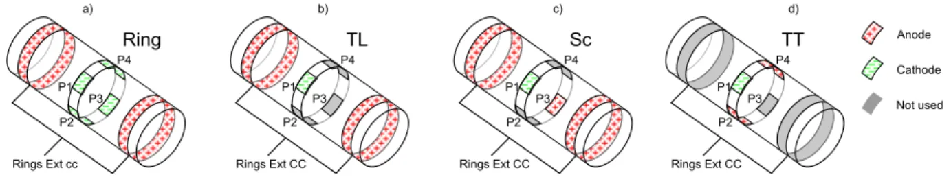
A multipolar cuff electrode (IMTEK, Germany) was used to test different spatial configurations. Embedded in lay-ers of polyimide thin-film, 11 sites were patterned in a 300 nm layer of platinum. Constituted by one ring in each extremity (0.5 x3.2 mm), 8 central contacts arranged in a spiral configuration (0.5 x0.25 mm, separated each other of 0.15 mm and distanced from rings by 3 mm) and one reference (0.5 x1.05 mm), this cuff electrode allowed test of monopolar, steering and transverse tripolar configura-tions. In practice, external rings were short-circuited, named Rings ext CC, and, according to configurations presented in the Fig. 1, only 4 (P 1, P 2, P 3, P 4) central contacts among 8 were used.
Intramuscular electrodes (lead-exposed isolated tungsten wires, custom made) were positioned in two antagonist muscles, theTAand theGAS, then, connected to a 16 chan-nel amplifier (G TEC, Austria). EMG signals were acquired using a POWERLABacquisition system (AD INSTRUMENTS, New Zealand), and results were displayed in real time,
Anode Cathode Not used Ring P1 P2 P3 P4 Rings Ext cc a) b) c) d) TL P1 P2 P3 P4 Rings Ext CC Sc P1 P2 P3 P4 Rings Ext CC TT P1 P2 P3 P4 Rings Ext CC
Fig. 1. Electrode configuration: in each configuration external rings are short-circuited. a) Ring configuration (Rings): all central poles configured in cathode and external rings in anode. b) Tripolar Longitudinal (TL ) configuration: only one pole configured in cathode and external rings in anode. c) Steering current (Sc) configuration: TL plus an additional anode on the central contact (at the opposite side of the cathode). d) Tripolar Transverse (TT ): two contacts of the central ring are set in anode on both cathode sides. See Tab. I for the current repartition.
Fig. 2. Miniaturized version of the multipolar stimulator
then, recorded for post-processing with LABCHARTsoftware (AD INSTRUMENTS, New Zealand).
B. Experimental stimulator
Stimulation patterns were delivered by a Stim’ND stim-ulator. Stim’ND is a benchtop stimulator manufactured by
AXONIC, whereas hardware and software (SENIS Manager [8]) were developed by our team (DEMAR, LIRMM-INRIA, Montpellier, France). It allows configuration and remotely control of frequency, pulse width and intensity in 12 channels independently, supplying, thus, complex stimulation profiles. It was designed according to active implantable medical device constraints. The core of the stimulator lies in two chips: an analog ASIC dedicated to stimulus generation (i.e. output stage) and a FPGAembedding the digital architecture [9] according to which the stimulator performs safe multi-polar stimulation and is remotely controlled. A miniaturized version of this multipolar stimulator has been developed with
AXONIC(Fig. 2) for human trials, and an implantable version
is under development.
The digital architecture of Stim’ND embeds a specific and very compact processor, similar to an application-specific instruction-set processor (ASIP), that runs micro-programs written in a FES-dedicated, reduced 32-bit instruction set. It configures the analog subsystem: configuration of active poles of the 12-channel output stage, configuration of their polarity (anode, cathode, high impedance), configuration of the current ratios between active poles, i.e. the output current on each active pole is a fraction (k/16) of the global programmed current. TheFES-dedicated processor drives the output stage according to the chosen stimulation profile, by calibrating the current pulse to be applied to the multipolar electrode which has been configured. Calibrating the current pulse means precisely controlling both the current magnitude
(from 1.3 µA to 5.3 mA with a 1.3 µA step (noted Istep)
for a 1/16 ratio) and the duration (1µ s step), according to the defined stimulation pattern. Complex waveforms can be defined. The current delivered at one pole contact p is defined as follow: Istim(p)= sign{p} ∗ N ∗ Istep∗ kp/16
so Istim(p)= sign{p} ∗ N ∗ 20.8 ∗ kp/16µA
Where: N is the number of current steps (from 0 to 255), V E = [k1, ..., k12] is the vector ratios defined for
the 12 pole contacts, the sign of p (sign{p}), positive or negative, corresponds respectively to the anodal or cathodal pole configuration.
In the following, the amplitude of current stimulation will refer to the sum of the injected cathodal current (which is equal to the sum of anodic one).
The original idea of the analog part is that instead of configuring 12 current sources, the ASIC configures the vector VE (Virtual Electrode) of ratios and controls only one current source. VE is then linked to the chosen con-figuration whereas the current source drives all the poles at the same time playing only with a scale effect analogous to recruitment. Ratios are thus strictly maintained whatever the global current is, which could not have been ensured with 12 current sources with equivalent resolution.
The digital part of the stimulator embeds the µprogram in charge of managing the global current, thus the stimulus waveform, and the swap between VE i.e. configurations. To our knowledge, this concept is completely new. As the stimulator is aimed at being used in humans, an independent model checks in parallel that critical constraints are satisfied regarding the maximum injected charges, the charge balance and the maximum frequency. Indeed, in a such complex way of performing the stimulation, it is almost impossible to guarantee these constraints a priori in all cases, and should be checked in real-time.
The aim of the multipolar stimulations we perform, using multipolar electrodes, is to focus the current on a specific part of the nerve, ideally on particular fascicles. The output stage configuration favors constant spatial localization, since poles configuration and ratios (VE ) should allow the recruitment of specific nerve portions, and playing with the global current (through a DACC) leads to deeper and finer axon activation.
TABLE I CONFIGURATION DETAILS P 1 P 2 P 3 P 4 Ring ext Configurations (k1) (k2) (k3) (k4) CC (k5) Ring -4 -4 -4 -4 16 Tripolar Longitudinal -16 0 0 0 16 Steering -16 0 8 0 8 Tripolar Transverse -16 8 0 8 0 C. Experimental procedure
Acute experiment was performed on one New Zealand white rabbit according to European ethical rules con-cerning animal experiments. After Anesthesia (Ketamine 26, 6 mg/kg/hr, Xylazine 1, 33 mg/kg/hr, Acepromazine 0, 266mg /kg/hr, a surgical incision was performed on the high part of the thigh. The sciatic nerve was carefully separated from surrounding tissues and one multipolar cuff electrode was rolled around it three centimeters above the peroneal / tibial nerve bifurcation. In consideration of tested configurations, a particular attention was carried regarding the positioning of the cuff electrode. After correct placement (electrode properly rolled around the nerve and contacts touching neural structure), the electrode was sutured to superficial tissues and the wound was partially closed.
The poles configuration anode/cathode for Ring, TL (Tripolar Longitudinal), Sc (Steering current) and TT (Tripo-lar Transverse) are reported in Fig. 1. In this example, the cathode set in P 1 is named 0◦ linked to its orientation.
The corresponding configuration current ratios (VE ) are reported in the Tab. I. Five values of VE are defined: the 5 first poles ratios k1 to k5 are set, the ratios of poles 6 to
12 (k6 to k12) are fixed to 0. In this table: a negative sign
indicates a pole configured in cathode, when a positive one is linked to an anodal configuration. The value represents the ratio (for a total of 16/16), for example a ratio of −16 declared for P 1 means that 16/16 so 100% of the total current goes through the cathode P 1; a ratio of −4 declared for P 2 means that 4/16 so 25% of the total current goes through the cathode P 2 (table I).
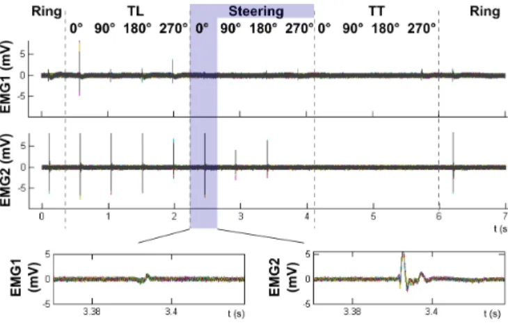
The pulse sequence can be described as follows: First, a 2500 µs pre-charge pulse [10] was delivered, followed by an active 250 µs pulse (with amplitude 10 times higher than the first one in order to balance the charge). Then ,the stimulator output was high impedance during 5 ms (to allow recording), and a passive discharge was set during 10 ms. For each current amplitude, 1 pulse sequence was delivered using ring configuration, then, 500 ms after the Sc0◦ was set, 500 ms after the Sc90◦and Sc180◦, Sc270◦, TT 0◦, TT 90◦, TT 180◦, TT 270◦, finally another ring was performed (obviously, each of these configurations also spaced by 500 ms), so a total of 14 pulse sequences (one scan) are tested for each current amplitude. For averaging purposes, each scan was repeated 10 times (10 scans per amplitude for each configuration, so a total of 140 pulses sequence). In total, six different amplitudes were tested 200, 220, 240, 260, 300, 400, 600 and 800 µA. So a total of 840 sequences were executed: 140 pulses sequence (or 10 scans) for 6 different amplitudes.
Fig. 3. Synchronisation ofGAS andTA EMGsignals.EMG signals were obtained after 10 repetitions of the same stimulation µprogram. For each configuration TL, Sc and TT, contacts at 0◦(1), 90◦(2), 180◦(3) and 270◦ (4) were successively used to assess spatial selectivity
The whole setup is software driven so that all the config-urations are automatically generated.
After acquisition, EMG signals were synchronized and averaged. Data processing was achieved using MATLAB (Mathworks, United States). The Root Mean square (RMS) value was calculated for each EMG signals in each stimu-lation session. This value was calculated over a window of 30 ms when the evoked action potentials (AP) occur. These
RMS values of evoked AP for GAS and TA muscles are normalized and reported in the recruitment curve Fig. 4.
III. RESULTS
First, we ensured that both recruitment curves for Ring configuration are similar, checking experiment stability (first and last sequences of each scan, not represented in the figure). Unsurprisingly, all tested configurations present the best selectivity performances for the same cathodal position-ing (cathode in P 1 or 0◦). Indeed, with this configuration, a selective activation of the TA muscle (i.e. without GAS
contraction) was achieved. The recruitment curve for this arrangement (0◦) are reported in Fig. 4; where x axis corresponds to the stimulation current amplitude and the y axis to the muscle recruitement. This figure highlights the selective activation of TA muscle for a 200 µA stimulation in the TL configuration (recruitment around 0.8 and 0.3 for the TA and the GAS respectively) and activation of both muscles for a current of 250 µA (recruitment around 1 for both muscles). In the same way, the Sc configuration activates the TA preferentially for a range of current from 200 µA to 300 µA (recruitment around 0.8 and 0.3 for the
TA and the GAS respectively). For a value above 300 µA this configuration activates both muscles (GAS recruitment around 0.8). Finally the TT configuration activates the TA
for current above 800 µA (GASwas not activated in this case for this range of current).
IV. DISCUSSION
Our results show that best selectivity performances are achieved in all configurations for the same cathodal position.
No rm al ize d recr uitem ent 0 200 400 600 800 1000 0 0.2 0.4 0.6 0.8 1 0 200 400 600 800 1000 0 0.2 0.4 0.6 0.8 1 0 200 400 600 800 1000 0 0.2 0.4 0.6 0.8 1 a) 0 200 400 600 800 1000 0 0.2 0.4 0.6 0.8 1 b) d) I(µA) I(µA) c) Gastrocnemius Tibialis anterior No rm al ize d recr uitem ent
Fig. 4. Comparison of Recruitment curves for the 4 configurations (Cathode in a similar position for each of them: 0◦): a) Tripolar Ring b) Tripolar Longitudinal, c) steering d) tripolar transverse. In x axis amplitude of stimulated current, in the y axis normalizedRMSvalue of theAP.
Selective activation ofTA(withoutGASresponse) is achieved for the 0◦ position (when the cathode is in P 1), suggesting the presence of TA fascicles close to P 1. The obtained results are in agreement with literature; The TL is able to selectively activate parts of the nerve in relationship with the TAmuscle for small current amplitudes. Then, adding a steering current increases the selectivity and increases the current range entailing selective activation. Finally TT is the most effective configuration (i.e. the most selective) but requires higher stimulation current.
In neural prosthetics (NP) application, configuration per-formances cannot only be considered in terms of selectivity. Current consumption and parameters setting simplicity are huge constraints. The high current consumption requisite for the TT can limit the life duration of a NP. So this configuration may not be the best one in this context. However, the best configuration is not necessary the less power consuming of the selective ones. In our case, the TL is selective for small current but in a too small range (span): Its use would make theNPdevice too difficult to calibrate. The Sc seems to constitute a good trade-off between selectivity, power consumption, and range of use but is probably not the optimal one.
Beyond these configurations, infinity of others need to be investigated. By providing huge flexibility in stimulation parameters and configurations, Stim’ND offers the oppor-tunity to increase ranges of possibilities. Furthermore, by showing objective comparisons of several configurations in this paper, we claim to be able to demonstrate the interest of new stimulation profiles by using the same methodology, i.e by scanning every configuration with the same device, providing thus repeatable and stable results.
V. CONCLUSION
We proposed a new approach to assess multipolar selective electrical neural stimulation and compare different advanced strategies performances. We designed a stimulator capable of accurately control complex stimulation patterns over 12 independent channels. We also performed experimental validation of our approach by reproducing some literature
results. We are, thus, able to test original multipolar advanced stimulation conditions through an automatic scanning of preprogrammed configurations. This allows to compare the configuration performances by testing selectivity on a same animal with similar experimental conditions.
ACKNOWLEDGEMENTS
Experiments were done at the Laboratoire de Chirurgie Exp´erimentale (Montpellier) with the help of H. Taillades.
REFERENCES
[1] S. C. M. a. Ordelman, L. Kornet, R. Cornelussen, H. P. J. Buschman, and P. H. Veltink, “Selectivity for specific cardiovascular effects of vagal nerve stimulation with a multi-contact electrode cuff.” IEEE trans. on Neural Systems and Rehab. Eng., vol. 21, no. 1, pp. 32–36, Jan. 2013.
[2] M. D. Tarler and J. T. Mortimer, “Selective and independent activation of four motor fascicles using a four contact nerve-cuff electrode.” IEEE trans. on Neural Systems and Rehabilitation Eng., vol. 12, no. 2, pp. 251–7, Jun. 2004.
[3] C. Veraart, W. M. Grill, and J. T. Mortimer, “Selective control of muscle activation with a multipolar nerve cuff electrode.” IEEE trans. on Biomed. Eng., vol. 40, no. 7, pp. 640–53, Jul. 1993.
[4] W. M. Grill and J. T. Mortimer, “Stability of the Input - Output Properties of Nerve Cuff Stimulating Electrodes,” IEEE Trans. on Biomed. Eng., vol. 6, no. 4, pp. 364–373, 1998.
[5] J. Badia, T. Boretius, D. Andreu, C. Azevedo-Coste, T. Stieglitz, and X. Navarro, “Comparative analysis of transverse intrafascicular mul-tichannel, longitudinal intrafascicular and multipolar cuff electrodes for the selective stimulation of nerve fascicles.” Journal of neural engineering, vol. 8, no. 3, p. 036023, Jun. 2011.
[6] T. N. Nielsen, G. a. M. Kurstjens, and J. J. Struijk, “Transverse Versus Longitudinal Tripolar Configuration for Selective Stimulation With Multipolar Cuff Electrodes,” IEEE Trans. on Biomed. Eng., vol. 58, no. 4, pp. 913–919, Apr. 2011.
[7] K. E. I. Deurloo, J. Holsheimer, and H. B. K. Boom, “Transverse tripolar stimulation of peripheral nerve: a modelling study of spatial selectivity.” Med. & Bio. Eng. & Comp., vol. 36, no. 1, pp. 66–74, 1998.
[8] D. Passama, R. Andreu and D. Guiraud, “Computer-based remote programming and control of stimulation units,” in 5th International IEEE EMBS Conf. on Neural Eng., Cancun, Mexico, May 2011, pp. 538–541.
[9] D. Andreu, D. Guiraud, and G. Souquet, “A distributed architecture for activating the peripheral nervous system,” J. Neural Eng., vol. 6, no. 2, p. 026001, 2009.
[10] W. M. Grill and J. T. Mortimer, “Stimulus waveforms for selective neural stimulation,” Eng. in Med. and Bio., vol. 14, pp. 375 – 385, 1995.