Publisher’s version / Version de l'éditeur:
Vous avez des questions? Nous pouvons vous aider. Pour communiquer directement avec un auteur, consultez la première page de la revue dans laquelle son article a été publié afin de trouver ses coordonnées. Si vous n’arrivez pas à les repérer, communiquez avec nous à [email protected].
Questions? Contact the NRC Publications Archive team at
[email protected]. If you wish to email the authors directly, please see the first page of the publication for their contact information.
https://publications-cnrc.canada.ca/fra/droits
L’accès à ce site Web et l’utilisation de son contenu sont assujettis aux conditions présentées dans le site
LISEZ CES CONDITIONS ATTENTIVEMENT AVANT D’UTILISER CE SITE WEB.
Internal Report (National Research Council of Canada. Division of Building
Research), 1983-10
READ THESE TERMS AND CONDITIONS CAREFULLY BEFORE USING THIS WEBSITE. https://nrc-publications.canada.ca/eng/copyright
NRC Publications Archive Record / Notice des Archives des publications du CNRC : https://nrc-publications.canada.ca/eng/view/object/?id=c9507633-3a0d-496d-b7c1-b0734f12c88e https://publications-cnrc.canada.ca/fra/voir/objet/?id=c9507633-3a0d-496d-b7c1-b0734f12c88e
NRC Publications Archive
Archives des publications du CNRC
For the publisher’s version, please access the DOI link below./ Pour consulter la version de l’éditeur, utilisez le lien DOI ci-dessous.
https://doi.org/10.4224/40001316
Access and use of this website and the material on it are subject to the Terms and Conditions set forth at
Fire tests on reinforced concrete columns: specimen no. 12
Lie, T. T.
National Research
Council Canada
Conseil national
de recherches Canada
FIRE TESTS ON REINFORCED CONCRETE COLUEfNS, SPECIMEN NO. 1 2 by T.T. L i e and T.D. L i n
Private
copy for:NATIONAL RESEARCH COUNCIL OF CANADA DIVISION OF BUILDING RESEARCH
DBR INTERNAL REPORT NO. 489
FIRE TESTS ON REINFORCED CONCRETE COLUMNS, SPECIMEN NO.
12
by T.T. Lie and T.D. Lin
Checked by: T
.
Z
.
H.
Approved by:L.W.
Gold Date: October1983
Prepared for: Record Purposes
ABSTRACT
Results of a fire test on a reinforced concrete column are given. The test is one of a series of twelve tests carried out in the first phase of a joint study on the fire performance of concrete columns
by
the National Research Council Canada and the Portland C c m m t Association. The column was made with carbonate aggregate.ILs secLion h i z e w;is
305
x305
mm(12 x
12
in.). It was testedto determine the influence of aggregate on the fire resistance of the column.
FIRE TESTS ON REINFORCED CONCRETE COLITMNS SPECIMEN NO. 12
T.T. L i e and T.D. Lin*
T e s t s were c a r r i e d o u t on a s e r i e s of r e i n f o r c e d c o n c r e t e columns a s p a r t of a s t u d y t o develop methods f o r t h e d e t e r m i n a t i o n of t h e f i r e r e s i s t a n c e of such columns. The s t u d y was a c o o p e r a t i v e e f f o r t between t h e N a t i o n a l Research C o u n c i l Canada and t h e P o r t l a n d Cement
A s s o c i a t i o n . I n t h e f i r s t phase of t h e s t u d y 12 columns were t e s t e d . The columns were d e s i g n e d and manufactured by PCA i n Skokie, I l l i n o i s , and t e s t e d i n t h e NRCC l a b o r a t o r i e s i n Ottawa. The test specimens, method of t e s t i n g and t e s t r e s u l t s a r e d e s c r i b e d i n s u c c e s s i v e r e p o r t s .
This r e p o r t d e a l s w i t h specimen No. 12, which was t e s t e d t o determine t h e i n f l u e n c e of a g g r e g a t e on t h e f i r e r e s i s t a n c e of t h e column.
TEST SPECIMEN
The specimen c o n s i s t e d of a s q u a r e t i e d r e i n f o r c e d c o n c r e t e column. D e t a i l s of t h e specimen and i t s f a b r i c a t i o n a r e g i v e n below.
S e c t i o n s i z e : 305 x 305
rmn
(12 x 12 i n . ) Height: 3810 mm (12 f t6
in.)Materials
Cement: Type I, a g e n e r a l purpose cement f o r t h e c o n s t r u c t i o n of r e i n f o r c e d c o n c r e t e s t r u c t u r e s .
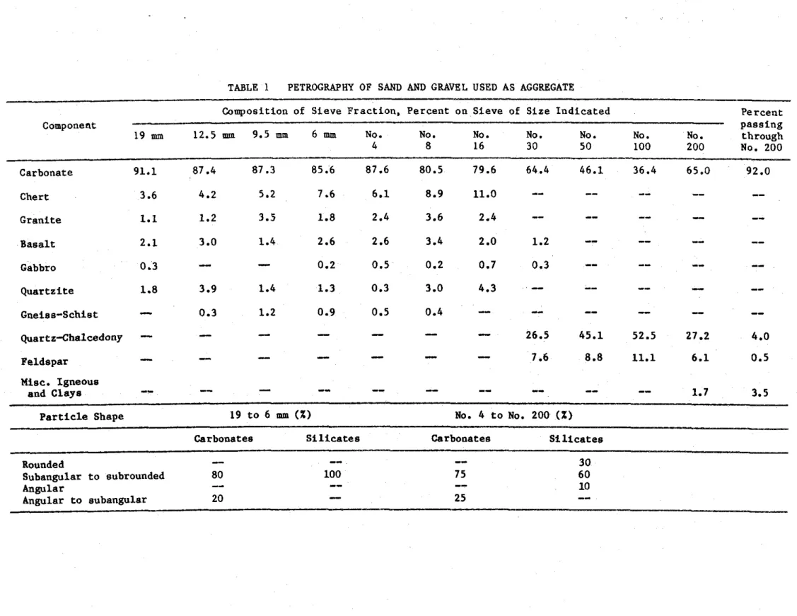
Aggregate: Carbonate sand and g r a v e l from E l g i n , I l l i n o i s . The maximm s i z e of t h e a g g r e g a t e was 19 mm ( 3 1 4 in.). The g r a d a t i o n c u r v e i s shown i n Fig. 1. P e t r o g r a p h i c i n f o r m a t i o n , g i v e n i n Table 1, w a s o b t a i n e d f o l l o w i n g t h e p r o c e d u r e s of ASTM ~295-7g1. P h y s i c a l p r o p e r t i e s of aggregate: S p e c i f i c g r a v i t y of s a n d (2.67); s p e c i f i c g r a v i t y of g r a v e l (2.67); m o i s t u r e c o n t e n t of s a n d (3.0%); m o i s t u r e c o n t e n t of g r a v e l (1.0%); s a t u r a t e d s u r f a c e d r y u n i t weight of g r a v e l (1712 kg/m3) (107.0 l b / f t 3 ) ; f i n e n e s s modulus of f i n e a g g r e g a t e (3.00); f i n e n e s s modulus of c o a r s e a g g r e g a t e (1.53).
*Senior r e s e a r c h e n g i n e e r , P o r t l a n d Cement A s s o c i a t i o n , Skokie, I l l i n o i s .
S t e e l r e i n f o r c e m e n t : Deformed 25M (No. 8 ) l o n g i t u d i n a l
r e i n f o r c i n g b a r s and 10M (No. 3 ) t i e s , m e e t i n g t h e r e q u i r e m e n t s of ASTM D e s i g n a t i o n ~615-602. The y i e l d s t r e s s of t h e 25M b a r s w a s 443.7 MPa
(64.3 k s i ) and t h a t of t h e 10M b a r s , 426.5 MPa (61.8 k s i ) . The
u l t i m a t e s t r e n g t h of t h e 25M b a r s was 730 MPa (105.8 k s i ) and t h a t of t h e 10M b a r s , 671 MPa (97 k s i ) .
Concrete mix: The c o n c r e t e mix was d e s i g n e d t o produce a 34.5 MPa (5000 p s i ) s t r e n g t h n o w a i r e n t r a i n e d c o n c r e t e . A waterlcement r a t i o of 0.6 was used. The slump was 77 mm (3.04 in.). Batch q u a n t i t i e s a r e a s f o l l o w s : cement, 345.9 kg/m3 (583 1 b l y d 3 ) ; c o a r s e a g g r e g a t e ,
1065.5 kg/m3 (1796 1 b j y d 3 ) ; s a n d , 815.8 kg/m3 (1375 1 b l y d 3 ) ; w a t e r , 192.8 kg/m3 (325 1 b I y d 3 ) . The measured p r o p e r t i e s of t h e c o n c r e t e were: a i r c o n t e n t , 1.80%; d e n s i t y , 2412 kg/m3 (150.53 l b / f t 3);
compressive s t r e n g t h a t 28 d a y s ( c a s t d a t e , 29 August 1977), 34.2 MPa (4960 p s i ) .
Fabrication
C a s t i n g
The column was c a s t i n
a
s p e c i a l l y d e s i g n e d form. A t t h e s t a r t o f c a s t i n g , t h e f r o n t of t h e form was l e f t open f o r d e p o s i t i n g f r e s hc o n c r e t e . The c o n c r e t e was mixed i n a 0.17 m 3
(6
cu. f t . ) t i l t i n g drum mixer. Shovels and scoops were u s e d t o d e p o s i t c o n c r e t e i n t h e form. A small i n t e r n a l v i b r a t o r was a p p l i e d t o c o n s o l i d a t e t h e c o n c r e t e . A sc a s t i n g p r o g r e s s e d upwards, t h e window p i e c e s were s u c c e s s i v e l y c l o s e d and t i g h t l y b o l t e d t o t h e form t o a v o i d p o s s i b l e m o i s t u r e l e a k s .
L i f t i n g hooks were embedded on o p p o s i t e s i d e s of t h e t e s t specimen 800 mm ( 2 f t 7 112 i n . ) from t h e t o p of t h e column. A c y l i n d r i c a l humidity we113 w i t h a d i a m e t e r of 4 mm (5132 i n . ) was p o s i t i o n e d a t mid-height of t h e column f o r measuring t h e r e l a t i v e humidity a t mid- depth.
R e i n f o r c i n g cage
The r e i n f o r c i n g cage was assembled by welding each end of f o u r l o n g i t u d i n a l main r e i n f o r c i n g b a r s t o a s t e e l end p l a t e . The b a r s were c u t t o 3800 mm (12 f t 5 112 i n . ) and machined a t b o t h e n d s , f o r a
l e n g t h of 19 mm (314 i n . ) t o a d i a m e t e r of 19 mm. F i g u r e 2 shows d e t a i l s of t h e f i n i s h e d b a r s . The dimensions of t h e end p l a t e s were 533 x 533 x 25 mm ( 2 1 x 21 x 1 in.). I n e a c h c o r n e r of t h e p l a t e , 20.6 mm (13116 i n . ) h o l e s were d r i l l e d t o accommodate t h e l o n g i t u d i n a l b a r s . The c e n t e r s of t h e h o l e s were s p a c e d 92.1 mm ( 3 518 i n . ) from t h e c e n t e r l i n e s of t h e p l a t e s . I n t h i s way a column was o b t a i n e d w i t h a s e c t i o n of 305 x 305 mm (12 x 12 in.) and a c o v e r of 47.6 mm ( 1 718 i n . ) t o t h e main r e i n f o r c i n g b a r s and 38.1 mm (1 112 i n . ) t o t h e s t i r r u p s . The main b a r s and s t i r r u p s were t i e d t o g e t h e r t o complete t h e s t e e l cage which, i n c l u d i n g t h e s t e e l p l a t e s , was 3810 mm
Welding
The p r o v i s i o n s of AWS D e s i g n a t i o n 012.1-754 were followed when welding p l a t e s and b a r s . These members were p r e h e a t e d w i t h a propane t o r c h t o 288OC (550°F), t o p r e v e n t b r i t t l e f a i l u r e d u r i n g welding. The s i d e f i l l e t weld was done around b a r s on t h e i n n e r f a c e of t h e bottom p l a t e . McKay E10018-D2 and DYTRON-579 welding r o d s were used. Both t y p e s of welding r o d s have t e n s i l e s t r e n g t h of 835 MPa (121 000 p s i ) . M i l d - s t e e l welding r o d s were used t o f i l l up t h e 6 mu ( 1 / 4 i n . ) deep
h o l e s on t h e o u t e r f a c e s of t h e p l a t e . The rough s u r f a c e s of t h e welded j o i n t s on t h e o u t e r f a c e of t h e p l a t e were ground t o a smooth f i n i s h .
The welding of t h e t o p s t e e l p l a t e was performed a f t e r t h e c a s t i n g of t h e columns. Before p o s i t i o n i n g t h e t o p p l a t e , a 6 mm (114 i n . ) l a y e r of mortar was s p r e a d o v e r t h e t o p of t h e column t o e n s u r e good c o n t a c t between s t e e l and c o n c r e t e . The mortar was made of one p a r t cement and t h r e e p a r t s s i l i c e o u s sand. Using t h e same procedure a s f o r t h e bottom p l a t e , t h e t o p p l a t e was welded on t h e o u t e r s i d e t o t h e b a r s and smoothed.
Curing
The c o n c r e t e was cured under damp b u r l a p f o r 7 days a t 21 t o 24OC ( 7 0 t o 75°F). The form was t h e n s t r i p p e d , and t h e column c o n d i t i o n e d i n an atmosphere c o n t r o l l e d a t 21 t o 24°C (70 t o 7S°F) and 30 t o 40% r e l a t i v e humidity.
The column was removed from t h e k i l n p e r i o d i c a l l y t o c o o l a t 23OC ( 7 3 ° F ) s o t h a t t h e r e l a t i v e humidity c o u l d be measured. M o i s t u r e c o n t e n t i n t h e column d u r i n g t h e d r y i n g p e r i o d is g i v e n below.
Days a f t e r R e l a t i v e humidity c a s t i n g c e n t e r of column (%)
Two hundred f o r t y - f i v e days a f t e r c a s t i n g , t h e r e l a t i v e humidity i n t h e c e n t e r of t h e column reached 86%, and t h e column was wrapped i n p l a s t i c t o p r e v e n t change of i t s m o i s t u r e c o n t e n t .
Thermocouples
Butt-welded chromel-alumel thermocouples w i t h a t h i c k n e s s of 0.912 mm (0.0359 i n . ) were used t o make thermocouple frames f o r
measuring c o n c r e t e t e m p e r a t u r e s a t d i f f e r e n t l o c a t i o n s i n v a r i o u s c r o s s s e c t i o n s of t h e columns. Each frame c o n s i s t e d of a number of thermo- couples t i e d t o s t e e l r o d s t h a t were f i r m l y s e c u r e d t o t h e main
r e i n f o r c i n g b a r s . Temperatures were measured a t t h r e e l e v e l s : a t one- q u a r t e r h e i g h t , a t mid-height and a t t h r e e - q u a r t e r h e i g h t of t h e
l e n g t h of a c e n t e r l i n e and a d i a g o n a l of t h e s e c t i o n ; a t t h e o t h e r two l e v e l s t h e t e m p e r a t u r e s were measured o n l y a l o n g h a l f of t h e c e n t e r l i n e and h a l f of t h e d i a g o n a l of t h e s e c t i o n . The l o c a t i o n of t h e
thermocouples i n t h e c o n c r e t e and t h e i r numbering a r e shown i n Figs. 3
and It.
I n a d d i t i o n , a number of thermocouples were mounted on t h e
r e i n f o r c i n g s t e e l b a r s and t i e s . The l o c a t i o n s of t h e thermocouples on t h e s t e e l a r e shown i n Fig. 5 and i n more d e t a i l i n Fig. 6.
A l l thermocouples were i n s t a l l e d i n such a way t h a t t h e w i r e followed an i s o t h e r m f o r a t l e a s t 12.7 mm (112 i n . ) from t h e j u n c t i o n . T e s t Apparatus
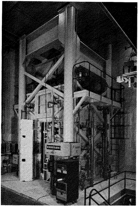
The t e s t was c a r r i e d o u t by exposing t h e column t o h e a t i n a
f u r n a c e s p e c i a l l y b u i l t f o r t e s t i n g l o a d e d columns and w a l l s . The t e s t f u r n a c e was designed t o produce t h e c o n d i t i o n s t o which a member might be exposed d u r i n g a f i r e , i . e . t e m p e r a t u r e s , s t r u c t u r a l l o a d s , and h e a t t r a n s f e r . It c o n s i s t s of a s t e e l framework s u p p o r t e d by f o u r s t e e l columns, w i t h t h e f u r n a c e chamber i n s i d e t h e framework ( F i g . 7). The c h a r a c t e r i s t i c s and i n s t r u m e n t a t i o n of t h e f u r n a c e a r e d e s c r i b e d i n d e t a i l i n r e f e r e n c e 5. Only a b r i e f d e s c r i p t i o n of t h e f u r n a c e and t h e main components w i l l be g i v e n h e r e . Loading Device Three h y d r a u l i c j a c k s produce f o r c e s a l o n g t h e t h r e e p r i n c i p a l a x e s . The j a c k a c t i n g a l o n g t h e a x i s of t h e t e s t column i s l o c a t e d a t
t h e hottom of t h e f u r n a c e chamber. The p l a t e on t o p of t h i s j a c k can he used a s a p l a t f o r m t o which t h e column can be a t t a c h e d .
Furnace Chamber
The f u r n a c e chamber has a f l o o r 2642 mm ( 8 f t 8 i n . ) on each s i d e and is 3048 mm (10 f t ) high. It i s made of i n s u l a t i n g m a t e r i a l s t h a t w i l l produce a h i g h h e a t t r a n s f e r t o t h e specimen. There a r e 32
propane gas b u r n e r s i n t h e f u r n a c e chamber, a r r a n g e d i n e i g h t columns c o n t a i n i n g f o u r b u r n e r s each. The t o t a l c a p a c i t y of t h e b u r n e r s is 4700 kW (16 m i l l i o n ~ t u / h ) . Each b u r n e r can be a d j u s t e d i n d i v i d u a l l y , which a l l o w s a h i g h t e m p e r a t u r e u n i f o r m i t y i n t h e f u r n a c e chamber. The p r e s s u r e i n t h e f u r n a c e chamber i s a l s o a d j u s t a b l e . It was s e t
somewhat lower t h a n a t m o s p h e r i c p r e s s u r e . I n s t r u m e n t a t i o n
The f u r n a c e t e m p e r a t u r e s a r e measured w i t h t h e a i d of e i g h t chromel-alumel thermocouples. The j u n c t i o n of each thermocouple was l o c a t e d 305 mm ( 1 f t ) from t h e t e s t specimen, a t v a r i o u s h e i g h t s . Two thermocouples were placed o p p o s i t e each o t h e r e v e r y 610 mm (2 f t ) a l o n g t h e h e i g h t of t h e f u r n a c e chamber. The l o c a t i o n of t h e i r j u n c t i o n s and t h e i r numbering a r e shown i n F i g . 8. Thermocouples No. 4 and 6 were
l o c a t e d a t a h e i g h t of 610 mm ( 2 f t ) from t h e f l o o r , thermocouples No. 2 and 8 a t 1220 mm (4 f t ) , thermocouples No. 3 and 5 a t 1830 mm (6 f t ) and thermocouples No. 1 and 7 a t 2440 mm ( 8 f t ) . The
t e m p e r a t u r e s measured by t h e thermocouples a r e averaged a u t o m a t i c a l l y and t h e average t e m p e r a t u r e used a s t h e c r i t e r i o n f o r c o n t r o l l i n g t h e f u r n a c e temperature.
The l o a d s a r e c o n t r o l l e d and measured w i t h t h e a i d of p r e s s u r e t r a n s d u c e r s . The a c c u r a c y of c o n t r o l l i n g and measuring l o a d s i s w i t h i n 5% a t lower l o a d l e v e l s and b e t t e r a t h i g h e r loads.
The a x i a l deformation of t h e t e s t specimen i s determined by measuring t h e displacement of t h e j a c k t h a t s u p p o r t s t h e column. The displacement i s measured w i t h t h e a i d of t r a n s d u c e r s w i t h a n a c c u r a c y of 0.002 mm (7.87 x i n . ).
Test Conditions
and
Procedure
The column was i n s t a l l e d i n t h e f u r n a c e by b o l t i n g i t s end p l a t e s t o a l o a d i n g head a t t h e t o p and a h y d r a u l i c j a c k a t t h e bottom. E i g h t 19 mm (314 i n . ) b o l t s , spaced r e g u l a r l y around t h e column 63.5 mm
( 2 112 i n . ) from t h e s i d e s , were used a t e a c h end.
On t h e day of t h e t e s t , t h e m o i s t u r e c o n d i t i o n i n t h e c e n t e r of t h e column was measured w i t h a Monfore gauge3. The r e l a t i v e humidity measured p r i o r t o t h e s t a r t of t h e t e s t was 76%. The ambient
t e m p e r a t u r e a t t h e s t a r t of t h e t e s t was 23°C (74'F).
The column was s u b j e c t e d t o a l o a d of 1778 kN (400 k i p s ) , which was a p p l i e d a b o u t one hour p r i o r t o t h e t e s t . The compressive s t r e n g t h of t h e c o n c r e t e a t t h e t e s t d a t e , measured on two c y l i n d e r s , was
38.5 MPa (5580 p s i ) and 41.4 MPa (5996 p s i ) . The column was c a s t on t h e 30th of August 1977 and t e s t e d on t h e 22nd of January 1982.
During t h e t e s t t h e column was exposed t o h e a t i n g c o n t r o l l e d s o t h a t t h e a v e r a g e t e m p e r a t u r e i n t h e f u r n a c e f o l l o w e d a s c l o s e l y as p o s s i b l e t h e ASTM-E1196 o r ULC-S1017 s t a n d a r d temperature-time curve. T h i s curve c a n be approximately d e s c r i b e d by t h e f o l l o w i n g equation:
where
Tf = temperature i n OC, and
where
Tf = temperature i n OF.
During t h e t e s t , t e m p e r a t u r e s i n t h e f u r n a c e and i n t h e column were measured a t t h e l o c a t i o n s d e s c r i b e d e a r l i e r . The a x i a l s t r a i n of
t h e column was a l s o measured. The column was r e g a r d e d t o have f a i l e d , and t h e t e s t was t e r m i n a t e d , when t h e h y d r a u l i c j a c k , which h a s a maximum speed of 76 mmlmin ( 3 in./min), could no l o n g e r m a i n t a i n t h e a p p l i e d load.
TEST RESULTS
Measured Temperatures and S t r a i a s
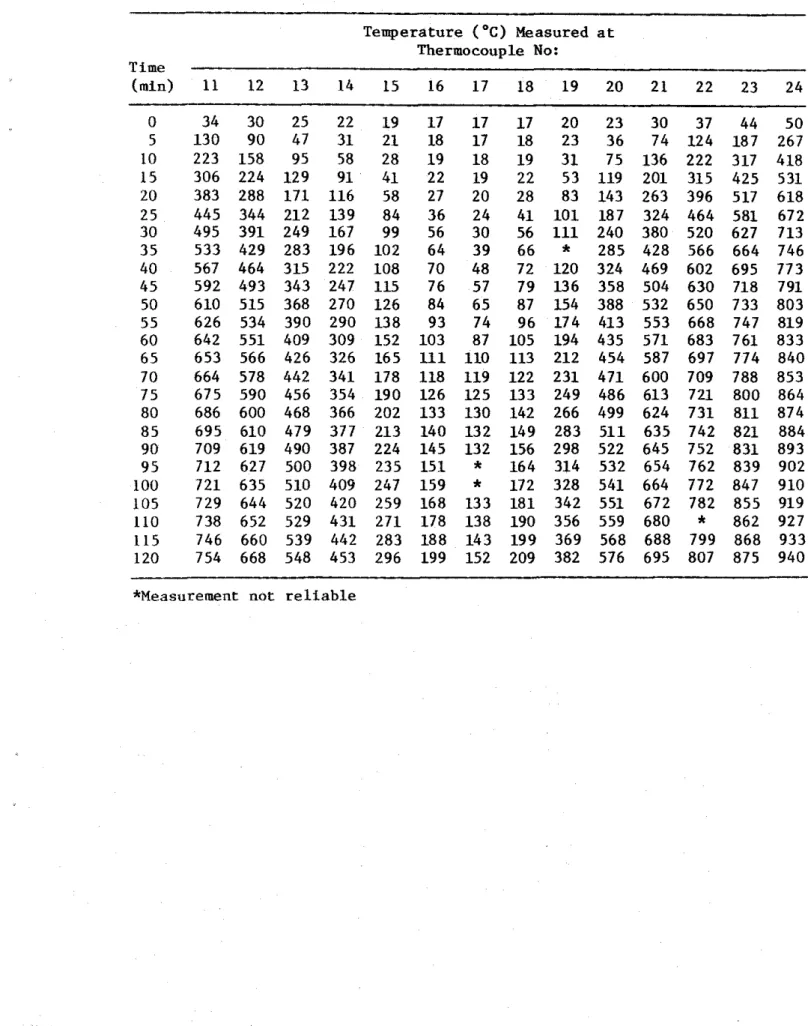
I n Table 2 t h e s t e e l t e m p e r a t u r e s a r e g i v e n f o r v a r i o u s t i m e s . The t e m p e r a t u r e s measured i n t h e c o n c r e t e s e c t i o n s a r e l i s t e d i n T a b l e s 3A-D.
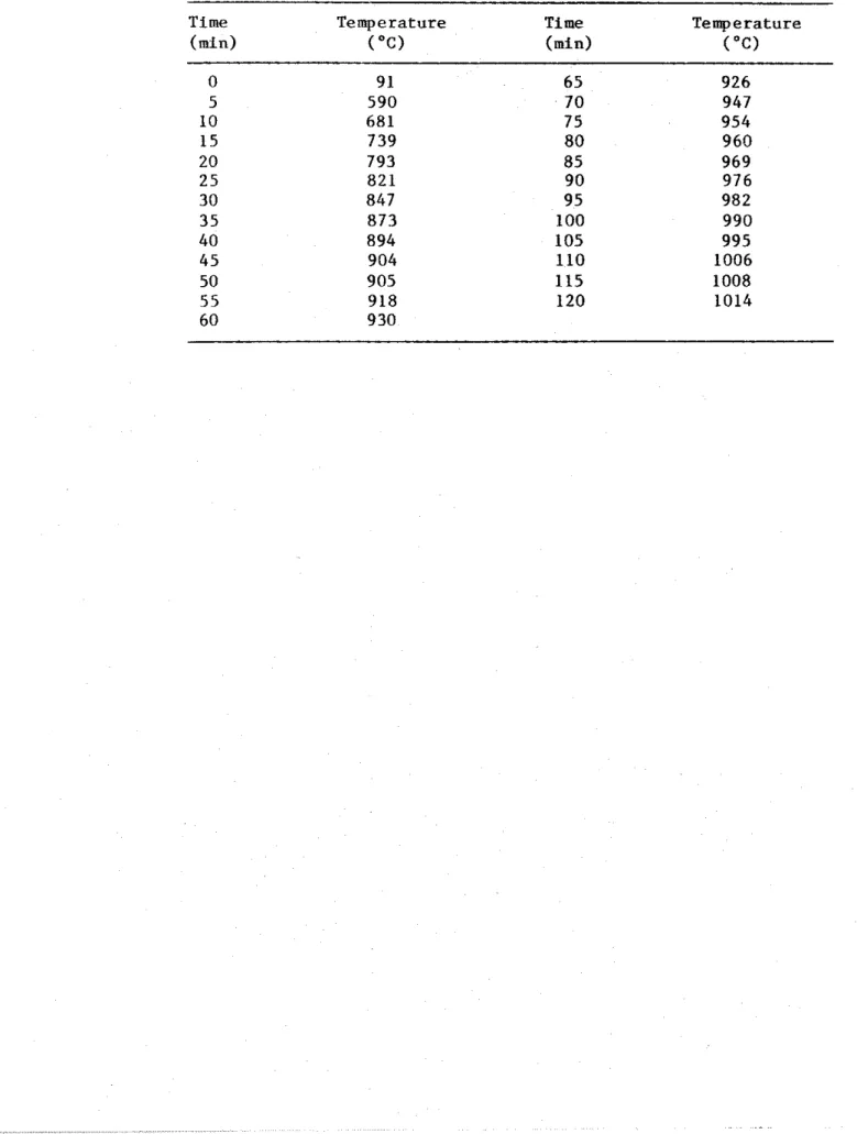
I n Table 4 t h e average f u r n a c e t e m p e r a t u r e s a r e g i v e n and i n T a b l e 8 t h e measured a x i a l deformation of t h e column, f o r v a r i o u s t i m e s d u r i n g t h e test.
O b s e r v a t i o n s
The f o l l o w i n g o b s e r v a t i o n s were made d u r i n g t h e t e s t . T e s t time H r :Min 0:00 F i r e s t a r t e d . 0:02 Furnace t e m p e r a t u r e reached 361°C (681°F). 0 : 0 5 Column s l i g h t l y expanded. 0:30 Column glowed a t c o r n e r s . 0:50 No c r a c k s were observed. 1:00 A h a i r l i n e c r a c k on e a s t f a c e of column, about 1222 mm (4 f t ) from f u r n a c e bottom, was seen.
1:15 One o r two h a i r l i n e c r a c k s , 51 t o 102 mm (2 t o 4 i n . ) i n l e n g t h , appeared a t mid-height r e g i o n o n a l l f o u r s i d e s of t h e column.
1:50 Column s t a r t e d t o c o n t r a c t slowly.
2:05 Cracks on e a s t f a c e lengthened, two l o n g c r a c k s j o i n e d t o g e t h e r .
2: 15 Cracks on e a s t f a c e widened t o 0.3 mm (118 i n . ) 2:33 Cracks on n o r t h f a c e worsened.
2:50 Cracks on e a s t and west f a c e s extended; some were 458 mm (18 i n . ) long.
3:08 Cracks on n o r t h f a c e were about 611 mm (24 i n . ) l o n g and 3.2 mm (118 in.) wide.
3:25 Cracks on e a s t f a c e opened t o a width of 6.4 mm (114 i n . ) . 3:28 Cracks on n o r t h f a c e were about 6.4
-
9.5 mm (114-318 i n . )wide.
3:32 Cracks on n o r t h and s o u t h f a c e s widened t o 12.7 mm (112 in. ).
3:35 Cracks on e a s t f a c e reached 916 mm ( 3 f t ) l o n g and 12.7 mm (112 in.) wide. A t t h i s moment, column f a i l e d i n
compression. Concrete cover on a l l f o u r s i d e s n e a r t h e upper q u a r t e r p o i n t a r e a ruptured. A t t h e c e n t e r of t h e f a i l e d p o r t i o n , a d i a g o n a l c r a c k developed through t h e c o r e of t h e column, and a l l main b a r s buckled.
I n Fig. 9, t h e column i s shown a f t e r t h e t e s t .
DISCUSSION OF
RESaTSF i g u r e 10 shows two average t e m p e r a t u r e s o b t a i n e d from measurements on two r e i n f o r c i n g b a r s d u r i n g t h e t e s t . These
measurements were made w i t h thermocouples No. 3 and 9 l o c a t e d o p p o s i t e t o e a c h o t h e r w i t h r e s p e c t t o t h e c e n t e r of one b a r , and w i t h
thermocouples No. 4 and 10, l o c a t e d o p p o s i t e t o each o t h e r on a n o t h e r b a r (Fig. 6 ) .
The t e m p e r a t u r e s measured on t h e s t e e l by t h e i n d i v i d u a l thermo- c o u p l e s a r e shown i n Fig. 11. The d i f f e r e n c e i n t e m p e r a t u r e between two o p p o s i t e p o i n t s of a b a r i s r e l a t i v e l y small.
No c a l c u l a t i o n s were made of t h e f i r e r e s i s t a n c e of t h i s column, because t h e m a t e r i a l p r o p e r t i e s of t h e c a r b o n a t e a g g r e g a t e c o n c r e t e , of which t h e column was made, were n o t s u f f i c i e n t l y known. A comparison w i t h t h e f i r e r e s i s t a n c e of a s i m i l a r column9, made w i t h s i l i c e o u s a g g r e g a t e and t e s t e d under t h e same l o a d , shows t h a t t h e r e s i s t a n c e of t h e c a r b o n a t e a g g r e g a t e c o n c r e t e column was a b o u t 50% h i g h e r t h a n t h a t of t h e s i l i c e o u s a g g r e g a t e column.
1. Standard P r a c t i c e f o r Petrographic Examination of Aggregates f o r Concrete, (1979). ASTM C295-79, American Society f o r T e s t i n g and M a t e r i a l s , Philadelphia.
2. Standard S p e c i f i c a t i o n f o r Deformed and P l a i n Bullet-Steel Bars f o r Concrete Reinforcement, (1980). ASTM A615-80, American Society f o r T e s t i n g and M a t e r i a l s , Philadelphia.
3.
Monfore, G.E. (1962). A Small Probe-Type Gauge f o r Measuring R e l a t i v e Humidity. J o u r n a l of t h e PCA Research and Development Laboratories, Vol. 5, No. 2.4.
Reinforcing S t e e l Welding Code, (1 975). AWS-D12.1-75, American Welding Society, Manlius,NY.
5. Lie, T.T. (1980). New F a c i l i t y t o Determine F i r e Resistance of Columns, Canadian Journal of C i v i l Engineering, Vol. 7, No. 3. 6. Standard Methods of F i r e T e s t s of Building Construction and
Materials, (1979). ANSIfASTM E119-79, American Society f o r Testing and M a t e r i a l s , Philadelphia.
7. Standard Methods of F i r e Endurance T e s t s of Building Construction and Materials, (1980). ULC SlOl M1980, Underwriters' Laboratories of Canada, Scarborough, Ontario.
8. Lie, T.T. and Harmathy, T.Z. (1972). A Numerical Procedure t o C a l c u l a t e t h e Temperature of P r o t e c t e d S t e e l Columns Exposed t o Fire. F i r e Study No. 28, Division of Building Research, National Research Council Canada, Ottawa, NRCC 12535.
9.
Lie, T.T., Allen, D.E., Lin, T.D. and Abrams, M.S. F i r e Resistance of Reinforced Concrete Columns, Division of Building Research, National Research Council Canada, Ottawa, t o be published.TABLE
1PETROGRAPHY OF SAND
AND GRAVEL USED AS AGGREGATE
Composition of Sieve Fraction, Percent on Sieve
ofSize Indicated
Percent
Component
passing
19
mm12.5
mm9.5
mm6
mmNo.
No.
No.
No.
No.
No.
No.
through
4
8
16
30
50
100
200
No. 200
Carbonate
91.1
87.4
87.3
85.6
87.6
80.5
79.6
64.4
46.1
36.4
65.0
92.0
Chert
3.6
4.2
5.2
7.6
6.1
8.9
11.0
--
--
--
--
--
Granite
Basalt
Gabbro
Quartzite
1.8
3.9
1.4
1.3
0.3
3.0
4 . 3-
--
--
-
--
Gneiss-Schist
-
0.3
1.2
0.9
0.5
0.4
-
--
--
-
-
--
Quartz-Chalcedony
-
-
-
-
-
-
-
26.5
45.1
52.5
27.2
4.0
-
-
-
-
-
- -
Feldspar
7.6
8.8
11.1
6.1
0.5
Misc. Igneous
and Clay8
-
--
-
--
--
-
--
--
--
--
1.7
3.5
Particle Shape
19 to 6
mm(XI
No.
4to No. 200
( X )Carbonates
Silicates
Carbonates
Si licates
Rounded
-
--
--
30
Subangular to subrounded
80
100
75
60
Angular
--
--
--
10
TABLE 2 MEASURED STEEL TEMPERATURES Temperature ('C) Measured a t Thermocouple No: Time ( m i d 1 2 3 4 5 6 7 8 9 1 0 0 1 9 20 20 5
*
24 24 10*
39 44 1 5 82 88 89 20 105 107 107 2 5 107 110 116 30 122 125 134 35 137 143 160 40 156 164 186 45 178 187 211 50 199 212 236 5 5 223 237 260 60 243 262 283 6 5 264 287 304 70 283 308 324 75 288 328 342 80 298 347 359 8 5 306 364 375 90 317 379 389 9 5 319 394 402 100 332 408 415 105 346 420 427 110 349 433 439 115 358 444 450 120 367 456 461 *Measurement n o t r e l i a b l eTABLE 3A CONCRETE TEMPERATURES
MEASURED
WITHTHERMOCOUPLES IN FRAME A
Temperature
(OC)
Measured a t Thermocouple No:Time
(min) 1 1
12
13
1415
16
1718
19
20
21
22
23
24
TABLE 38 CONCRETE TEMPERATURES MEASURED WITH THERMOCOUPLES I N FRAME B
--
Temperature (OC) Measured a t Thermocouple No: 'rime ( m i n ) 25 26 27 28 29 30 31 32 33 34 35 36 37 3 8 0 26 24 2 1 1 9 16 16 16 16 1 8 2 1 27 3 1 38 4 3 5 119 90 47 28 18 16 16 16 20 32 71 118 200 271 10 209 156 1 0 1 59 26 1 7 16 1 8 28 75 1 4 1 215 344 434 15 290 222 134 95 42 20 21 21 52 107 208 310 459 551 20 364 286 179 111 63 26
*
3 1 96 138 272 394 552 641 25 425 344 226 1 4 1 8 5 42 24 54 105 188 336 464 612 693 30 475 392 268 172 96 54 33 6 1 106 235 394 519 657 733 35 516 432 304 200 105 6 3 42 69 1 0 8 276 444 564 692 763 40 549 466 336 226 114 72 52 76 118 312 487 601 721 790 45 574 494 364 249 122 8 0 6 0 84 1 3 3 345 522 628 742 810 50 592 516 388 271 132 89 6 8 93 152 373 550 650 757 823 55 608 535 408 291 143 97 77 1 0 3 172 397 571 668 772 837 60 623 551 426 308 155 105 88 111 1 9 1 418 589 683 787 850 65 634 564 443 324 169 112 9 8 1 2 1 210 438 605 696 797 856 70 646 577 457 338 182 119 107 1 3 1 229 456 619 707 810 869 75 657 588 470 340 194 125 113 140 246 472 631 718 821 880 80 667 598 482 362 205 132*
147 262 486 642 728 832 890 8 5 676 608 492 373 216 137 122 154 278 499 652 738 842 899 90 684 616 501 382 226 1 4 3 127 160 293 510 662 748 850 907 9 5 691 623 510 391 237 149 1 3 1 166 307 520 670 758 858 914 100 699 631 518 401 247 155 134 173 320 530 679 767 865 923 105 707 638 527 411 258 1 6 3 137 182 333 539 686 776 872 931 110 714 646 536 422 269 172 140 192 346 548 694 785 879 938 115 722 653 544 433 281 182 146 203 359 556 701 793 886 944 120 729 660 553 443 292 193 152 214 371 564 707 800 893 951 *Measurement n o t r e l i a b l eTABLE 3C CONCRETE TEMPERATURES MEASURED WITH THERMOCOUPLES I N
FRAME C
' T i m e ( m i d-
0 5 10 15 20 2 5 30 3 5 40 45 50 55 60 6 5 70 7 5 8 0 8 5 90 9 5 100 105 110 115 120 Temperature ("C) Measured a t Thermocouple No: 40 41 42 4 3 44 45 46 47 48 49 50 51 52 28 24 21 18 16 16 16 1 9 22 30 35 44 58 117 58 35 20 16 16 17 21 3 8 8 6 135 239 337 205 116 68 28 18 16 18 31 89 167 248 401 508 285 165 100 44 21 17 21 60 123 247 350 516 617 359 220 129 78 34 1 9 31 101 165 320 434 600 694 421 271 164 92 4 8 28 47 107 219 386 501 654 741 469 311 184 95 5 1 36 58 107 263 442 552 695 776 508 347 217 100 59 44 66 115 301 489 593 723 804 540 378 243 106 67 52 74 131 335 529 624 741 830 563 404 269 117 76 6 0 8 3 149 366 558 648 760 845 580 427 292 130 86 68 93 168 392 579 665 774 853 596 446 312 144 97 76 104 189 414 596 680 789 867 610 463 330 159 106 88 113 210 434 610 693 803 881 621 478 347 174 113 99 1 2 3 230 451 624 705 810 884 632 490 361 188 119 106 132 249 466 637 716 824 895 642 501 374 200 125 111 139 266 480 649 727 837 906 652 512 385 212 132 114 147 283 493 660 737 848 914 661 520 396 223 138 117 153 298 506 670 748 858 923 670 530 406 234 145 120 160 313 517 680 759 866 930 678 538 417 246 154 124 168 327 527 690 769 874 937 686 547 427 257 163 129 178 341 537 699 780 8 8 3 944 694 555 438 269 173 134 188 354 546 708 789 890 951 702 564 449 280 182 139 198 366 554 716 797 897 956 709 572 460 292 192 147 209 379 563 723 804 903 961 717 581 471 304 202 156 220 391 570 730 811 908 967 *Measurement n o t r e l i a b l eTABLE 3D CONCRETE TEMPERATURES MEASURED
WITH
THERMOCOUPLES I N FRAME D--
Temperature ('C) Measured a t Thermocouple No: T i m e-
( m i n ) 53 54 55 56 57 58 59 6 0 6 1 62 6 3 64 65 66 0 21 19 17 15 13 12 12 12 14 16 21 25*
39 5 97 67 36 22 14 12 1 2 12 16 27 62 107*
255 10 172 125 80 45 20 1 3 12 1 3 26 88 126 200*
419 1 5 243 182 116 74 3 1 16 1 3 17 57 101 158 294*
535 20 310 237 151 105 52 21 16 26 97 121*
377*
622 25 366 287 188 111 76 39 20 46 105 175 186 446*
674 30 413 330 225 130 88 52 29 58 106 220 233 501*
711 35 453 368 258 151 97 60 3 8 66 110 255 263 545*
744 40 487 400 287 169 105 67 48 73 125 287 289 582*
*
45 513 427 312 187 112 75 57 8 1 1 4 3 318 323 609*
566 50 533 449 334 205 120 8 3 66 9 1 164 346 342 632*
626 55 549 468 354 223 131 9 1 7 5 1 0 3 184 371 355 650*
684 60 564 485 372 240 143 100 87 107 203 393 371 666*
710 6 5 577 500 388 256 154 111 100 113 223 413 389 680*
724 70 588 513 403 270 166 119 110 122 241 430 405 692*
732 75 599 526 417 284 178 125 118 131 259 446 419 704*
x 80 609 537 429 297 190 130 121 139 275 461 433 714*
*
8 5 618 547 441 310 202 133 122 147 292 474 445 722*
*
90 628 557 453 323 214 140 125 156 307 486 458 731*
*
9 5 636 567 464 336 225 146 130 167 322 498 471 740*
736 100 645 576 475 348 237 155 134 178 337 509 482 749*
740 105 653 585 485 361 249 165 139 189 351 520 494 758*
743 110 661 593 495 373 261 176 146 201 364 529 506 766*
744 115 669 602 504 385 272 187 154 212 377 539 516 775*
744 120 677 610 514 397 285 198 164 224 407 548 527 783*
745 "Measurement n o t r e l i a b l eTABLE 4 AVERAGE FURNACE TEMPERATURES T i m e T e m p e r a t u r e T i m e T e m p e r a t u r e ( m i d ( " C ) b i n ) ( " C ) 0 9 1 65 926 5 590 7 0 947 10 681 75 954 15 739 8 0 960 20 793 85 969 2 5 821 90 976 30 847 95 982 3 5 873 100 990 40 894 105 995 4 5 904 110 1006 50 905 115 1008 55 918 120 1014 60 930
TABLE 5
MEASURED
AXIAL
DEFORMATION OF COLUMN
Time
Deformation Time
Deformation Time
Deformation
(mid
(mm)(mid
(mm)
(Rid
(mm)
0
0
80
2.5
160
-0.7
5
0.4
85
2.5
165
-1.3
10
0.7
90
2.5
170
-1.9
15
1.1
9
5
2.5
175
-2.6
20
1.7
100
2.5
180
-3.4
25
1.9
105
2.4
185
-4.3
30
2.1
110
2.3
190
-5.3
35
2.2
115
2.2
195
-6.3
40
2
-3
120
2.0
200
-7.6
45
2.4
125
1.9
205
-8.8
50
2.5
130
1.6
210
-10.2
5
5
2.5
135
1.3
215
-11.9
60
2.5
140
1
.O
65
2.5
145
0.7
70
2.5
150
0.3
7
5
2.5
155
-0.1
(-)
sign indicates contraction of column past initial starting
position
m m
m m
m m
S T A N D A R D S I Z E O F S Q U A R E M E S H S I E V E
F I G U R E 1
P L A T E
P L A T E
F I G U R E 2
TIC
F R A M E A
&
S E C T I O N A - A
TIC
F R A M E B
O N B A C K
TIC
F R A M E C
ON
FRONT-
S E C T I O N B - B
TIC
F R A M E D
S E C T I O N C - C
TIC
F R A M E
F I G U R E
3
L A Y O U T O F T H E R M O C O U P L E F R A M E S
TIC
FRAME17
!6
15
14
13 12 11
A31
30
29
28
27
26 25
B
45
44
43
42
41 40 39
C59
58
57
56
55
54
53
D F I G U R E4
L O C A T I O N A N D N U M B E R S O F T H E R M O C O U P L E S I N A S E C T I O N48 mm CLEAR COVER TO M A I N REINFORCING BAR 4 25 M BAR 305 mm
305 mm 533 x 533 x 25 mm
THICK STEEL PLATE 7
r 7 6 mm M I N .
414 MPa 10 M BAR
F I G U R E 5
F I G U R E 6
T H E R M O C O U P L E S O N R E I N F O R C I N G B A R S 1305
mrn
x 305 rnm C O L U M N )FIGURE 7 TEST FURNACE
T O P V l E W ( E A S T S I D E ) S I D E V l E W
m
F I G U R E 8 L O C A T I O N A N D N U M B E R S O F T H E R M O C O U P L E SIN
C O L U M N F U R N A C E C H A M B E RFIGURE 9
- M E A S U R E D A V E R A G E T I C 3 . 9 M E A S U R E D 0 5 0 1 0 0 1 5 0 2 0 0 T I M E , m i n F I G U R E 1 0 M E A S U R E D A V E R A G E T E M P E R A T U R E S O F M A l N R E I N F O R C I N G B A R S T I M E , m i n F I G U R E 11 T E M P E R A T U R E S M E A S U R E D O N M A l N R E I N F O R C I N G B A R S