HAL Id: tel-00765011
https://tel.archives-ouvertes.fr/tel-00765011
Submitted on 14 Dec 2012HAL is a multi-disciplinary open access
archive for the deposit and dissemination of
sci-L’archive ouverte pluridisciplinaire HAL, est destinée au dépôt et à la diffusion de documents
Multi-functional nanocomposites for the mechanical
actuation and magnetoelectric conversion
Jiawei Zhang
To cite this version:
Jiawei Zhang. Multi-functional nanocomposites for the mechanical actuation and magnetoelectric conversion. Other. INSA de Lyon, 2011. English. �NNT : 2011ISAL0132�. �tel-00765011�
N° d’ordre 2011-ISAL-0132
Année 2011
THESE
Multi-functional Nanocomposites for the
Mechanical Actuation and
Magnetoelectric Conversion
By
Jiawei Zhang
A thesis submitted in fulfilment
of the requirements for the degree of
Doctor of Philosophy
School of doctorate: Electronic, Electrotechnic and Automatic (EEA)
INSA-LYON
Lyon, France
13 December 2011
Advisory Committee:
Advisor
Prof. Laurent LEBRUN
Co-Advisor
Prof. Benoit GUIFFARD
Reviewer
Prof. Colette LACABANNE
Reviewer
Dr.
Yves BERNARD (HDR)
Committee Member
Dr.
François BAUER
INSA Direction de la Recherche - Ecoles Doctorales – Quinquennal 2011-2015
SIGLE ECOLE DOCTORALE NOM ET COORDONNEES DU RESPON-SABLE
CHIMIE
CHIMIE DE LYON
http://www.edchimie-lyon.fr
Insa : R. GOURDON
M. Jean Marc LANCELIN
Université de Lyon – Collège Doctoral Bât ESCPE 43 bd du 11 novembre 1918 69622 VILLEURBANNE Cedex Tél : 04.72.43 13 95 [email protected] E.E.A.
ELECTRONIQUE, ELECTROTECHNIQUE, AUTO-MATIQUE
http://edeea.ec-lyon.fr
Secrétariat : M.C. HAVGOUDOUKIAN [email protected]
M. Gérard SCORLETTI
Ecole Centrale de Lyon 36 avenue Guy de Collongue 69134 ECULLY
Tél : 04.72.18 60 97 Fax : 04 78 43 37 17
E2M2
EVOLUTION, ECOSYSTEME, MICROBIOLOGIE, MODELISATION
http://e2m2.universite-lyon.fr
Insa : H. CHARLES
Mme Gudrun BORNETTE
CNRS UMR 5023 LEHNA
Université Claude Bernard Lyon 1 Bât Forel 43 bd du 11 novembre 1918 69622 VILLEURBANNE Cédex Tél : 04.72.43.12.94 [email protected] EDISS INTERDISCIPLINAIRE SCIENCES-SANTE http://ww2.ibcp.fr/ediss
Sec : Safia AIT CHALAL Insa : M. LAGARDE
M. Didier REVEL
Hôpital Louis Pradel Bâtiment Central 28 Avenue Doyen Lépine 69677 BRON
Tél : 04.72.68 49 09 Fax :04 72 35 49 16
INFOMATHS
INFORMATIQUE ET MATHEMATIQUES
http://infomaths.univ-lyon1.fr M. Johannes KELLENDONK Université Claude Bernard Lyon 1
INFOMATHS Bâtiment Braconnier 43 bd du 11 novembre 1918 69622 VILLEURBANNE Cedex Tél : 04.72. 44.82.94 Fax 04 72 43 16 87 [email protected] Matériaux MATERIAUX DE LYON Secrétariat : M. LABOUNE PM : 71.70 –Fax : 87.12 Bat. Saint Exupéry
M. Jean-Yves BUFFIERE
INSA de Lyon MATEIS
Bâtiment Saint Exupéry 7 avenue Jean Capelle 69621 VILLEURBANNE Cédex
Tél : 04.72.43 83 18 Fax 04 72 43 85 28
MEGA
MECANIQUE, ENERGETIQUE, GENIE CIVIL, ACOUSTIQUE
Secrétariat : M. LABOUNE PM : 71.70 –Fax : 87.12 Bat. Saint Exupéry
M. Philippe BOISSE
INSA de Lyon Laboratoire LAMCOS Bâtiment Jacquard 25 bis avenue Jean Capelle 69621 VILLEURBANNE Cedex Tél :04.72.43.71.70 Fax : 04 72 43 72 37 [email protected] ScSo ScSo* M. OBADIA Lionel
Sec : Viviane POLSINELLI Insa : J.Y. TOUSSAINT
M. OBADIA Lionel
Université Lyon 2 86 rue Pasteur 69365 LYON Cedex 07
RESUME
L’effet magnétoélectrique (ME) se traduit par la possibilité d’induire une magnétisation à l’aide d’un champ électrique (effet direct) ou celle d’induire une polarisation électrique à l’aide d’un champ magnétique (effet inverse). Les composites laminés qui possèdent de grands coefficients ME ont généré beaucoup d’intérêt dans le domaine des capteurs, des modulateurs, des interrupteurs et des inverseurs de phase.
Dans cette thèse, nous présentons les performances de composites dits laminés à deux ou trois couches. Il a été montré que l’on pouvait obtenir des performances en conversion ma-gnéto-électrique directe en associant des phases magnétostrictives et piézoélectriques. Une modélisation de leur comportement basée sur un oscillateur mécanique a été proposée. Elle a été en particulier utilisée pour simuler le couplage mécanique entre deux couches.
Une autre approche pour développer des dispositifs originaux a consisté à utiliser un champ magnétique alternatif pour induire des courants de Foucault dans des électrodes métalliques et une Force de Lorentz en présence d’un deuxième champ magnétique continu. Si ces élec-trodes recouvrent un matériau piézoélectrique, la force de Lorentz sera alors convertie en signal électrique suivant l’effet direct. Cette approche permet donc de développer des dispo-sitifs de conversion électromagnétique sans phase magnétique. Différents prototypes utili-sant un bimorphe piézoélectrique, un film de PVDF et une céramique piézoélectrique ont été réalisés et caractérisés. Un signal électrique proportionnel à la composante continue du champ magnétique a été mis en évidence, ce qui ouvre des applications pour la détection magnétique.
Cette thèse s’est également intéressée à l’augmentation du coefficient d’électrostriction par injection de charges électriques en utilisant la technique de décharge Corona. Cette étude a été réalisée sur du polypropylène, connu pour sa capacité à stocker des charges électriques. Le mécanisme de stockage de charge et l’effet sur l’électrostriction ont été étudiées par la mesure du potentiel de surface, la mesure des courants thermo-stimulés, la calorimétrie dif-férentielle et l’interférométrie Laser. L’injection de charges a contribué à une augmentation de la permittivité et par la même à celle du coefficient d’électrostriction, en accord avec un modèle simple de distribution de charges dans l’échantillon.
ABSTRACT
Magnetoelectric (ME) interactions in matter correspond to the appearance of magnetization by means of an electric field (direct effect) or the appearance of electric polarization by means of a magnetic field (converse effect). The composite laminates which possess large ME coefficient, have attracted much attention in the field of sensors, modulators, switches and phase inverters. In this thesis, we report on the ME performances of the bi- and tri- lay-ered composites. It is shown that their ME couplings can be achieved by combining magne-tostrictive and piezoelectric layers. A model based on a driven damped oscillation is estab-lished for the piezoelectric/magnetostrictive laminated composite. It is used to simulate the mechanical coupling between the two layers. In addition, we report that the ME coupling can be achieved without magnetic phase but only with eddy current induced Lorentz forces in the metal electrodes of a piezoelectric material induced by ac magnetic field. The models based on the Lorentz effect inducing ME coupling in PZT unimorph bender, polyvinylidene fluoride (PVDF) film and PZT ceramic disc are thus established. The results show the good sensitivity and linear ME response versus dc magnetic field change. Thus, the room tem-perature magnetic field detection is achievable using the product property between magnetic forces and piezoelectricity.
Besides, we report on the electrostrictive performance of cellular polypropylene electret af-ter high-voltage corona poling. We use the Surface Potential test, Thermal Stimulated Depo-larization Current experiment and Differential Scanning Calorimetry experiment to analyse its charge storage mechanism. The result show that the electrostrictive coefficient and rela-tive permittivity of the charged samples increase. Last but not least, in order to explain this phenomenon, a mathematic model based on the charged sample has been established.
I am a slow walker, but I never walk backwards.
Acknowledgments
I would like to express my sincere gratitude to my advisors, Prof. Laurent Lebrun and Prof. Benoit Guiffard, for giving me the opportunity to work on exciting projects. I would especially like to thank both of them for their warm guidance, encouragement and support throughout my Ph.D research at the INSA-Lyon. I deeply appreciate all the time and effort they spent discussing my projects and advising me. I also appreciate all their precious corrections to my papers and thesis, attentive consideration and encouragement they gave me. It would not have been possible to accomplish my scientific goals without their guid-ance. Also, without their selfless help, I can not get my research work done within few years.
I also would like to express my gratitude to the committee members:
Prof. Colette Lacabanne, Dr. Yves Bernard, Prof. François Bauer, Prof. Daniel Guyomar for their insightful, invaluable comments and suggestions that improved the quality of this work.
In addition, the same gratitude goes to Dr. Rabah Belouadah, Dr. Pierre-Jean Cottinet, Dr. Lauric Garbuio, Dr. Gael Sebald, Dr. Mickaë Lallart, Dr. Abdelowahed Hajjaji, Dr. Benjamin Ducharne and Dr. Jean-Fabien Capsal. It was a great opportunity and honor to join the Laboratory of Electrical Engineering and Ferroelectricity (LGEF), learn magnetical, mechanical and electrical characterizations of the composites films and discuss on theoreti-cal and technitheoreti-cal issues of my research work with them. Thanks also go to Dr. Laurence Seveyrat, Mr. Frederic Defromerie and Mrs. Véronique Perin for machining the art-like de-vice for my research and experiments.
I am also grateful for all the supports from Evelyne Dorieux, secretary of our labo-ratory. Thanks to all of her hard work, I can devote all my time to my studies and re-searches.
I would like to thank all members and colleagues in LGEF, as well as Bo Li, Ting Li and other friends in France who constantly help me not only in research but also in many aspects of my life during my Ph.D. study, though I can't list all of their names.
I also appreciate China Scholarship Council (CSC) for financial support.
Table of Contents
Introduction ... 6
Chapter 1. Literatures review and general concepts of Magnetoelectric and Electrostrictive effects ... 11
1.1 Introduction ... 11
1.2 Magnetoelectric effect ... 12
1.2.1 Review of magnetoelectric effect ... 12
1.2.2 History of ME effect ... 14
1.2.3 ME effect in single crystal phase material ... 15
1.2.4 ME effect in composite materials ... 18
1.2.5 ME coupling as a product property using Lorentz force effect... 23
1.2.5.1 Magnetostrictive/piezoelectric laminate composites ... 23
1.2.5.2 Brass ring around PZT disk ... 24
1.2.5.3 Crystal PMN-PT between two aluminium strips ... 24
1.2.6 Applications ... 25
1.3 Electrostrictive effect ... 27
1.3.1 Electroactive polymers (EAP) ... 27
1.3.2 Basic properties of electret ... 29
1.3.3 General concepts of Electrostrictive effect ... 31
1.3.4 Enhanced Electrostrictive performance of cellular polypropylene electret .... 33
1.3.4.1 Researches on polypropylene (PP) electret ... 33
1.3.4.2 Basic principles of corona charging technique ... 35
1.3.4.3 Charge storage mechanisms of polymeric electrets ... 37
1.4 Conclusion ... 39
Chapter 2. Sample preparation of laminate composites and their magnetoelectric experiments ... 41
2.1 Introduction ... 41
2.2 Multi-layer polymer composites ... 42
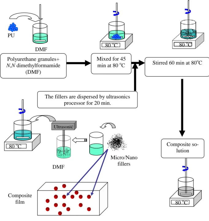
2.2.1 Film fabrication procedure ... 43
2.2.2 Tri- and bi-layered polymer composites fabrication ... 45
2.3 Experiments on piezoelectric unimorph bender and PVDF film ... 45
2.3.1 Early ME experiments on piezoelectric unimorph bender and PVDF ... 45
2.3.2 Magnetoelectric sensor based on piezoelectric unimorph bender ... 46
2.3.3 ME experiments on PVDF film ... 49
2.4 Magnetoelectric sensor based on a single piezoelectric ceramic disc . 51 2.5 Conclusion ... 52
Chapter 3. Experiments for analysing the charge storage mechanisms and the electrostriction of corona charged cellular PP ... 54
3.1 Introduction ... 54
3.3 Surface potential measurement ... 56
3.4 Relative permittivity measurement ... 57
3.5 Measurement of Young’s modulus ... 57
3.6 TSDC measurement ... 59
3.7 Differential scanning calorimetry measurement ... 60
3.7.1 Principle of data acquisition in the differential scanning calorimetry ... 60
3.7.2 Procedure of DSC test ... 61
3.7.3 Electrostrictive coefficient measurement ... 62
3.8 Conclusion ... 63
Chapter 4. Magnetoelectric results of laminate composites ... 65
4.1 Introduction ... 65
4.2 Magnetoelectric effect of laminate polymer composites ... 66
4.2.1 ME coupling in PU composite/PVDF laminates ... 66
4.2.2 Experimental results and calculation details ... 66
4.2.3 Modeling of the ME current of a multilayered sample ... 70
4.2.4 Effect of the first and second ME coefficients on phase shift ... 77
4.2.5 Effect of the linear ME coefficient αp ... 78
4.2.6 Effect of the bilinear ME coefficient βp ... 79
4.3 Magnetoelectric effect induced by eddy current in piezoelectric unimorph bender ... 81
4.3.1 Early ME experiments on piezoelectric unimorph bender... 81
4.3.1.1 Modelling of the piezoelectric unimorph bender ... 81
4.3.1.2 Calculation of ME coefficient based on the experiment ... 84
4.3.2 A developed ME sensor based on piezoelectric unimorph bender ... 86
4.3.3 ME effect caused by Lorentz force in a PVDF film ... 91
4.3.3.1 Mechanical model of bending PVDF film ... 91
4.3.3.2 ME effect of bending PVDF film ... 92
4.4 Magnetoelectric effect of single piezoelectric ceramic disc ... 94
4.4.1 Modelling of the magnetoelectric current induced by the Lorentz forces ... 94
4.4.2 Modelling of the output current when Bdc=0 ... 104
4.4.3 Modelling of the output current when Bdc≠0 ... 105
4.5 Conclusion ... 108
Chapter 5. Electrostrictive performance of the charged cellular PP .... 110
5.1 Introduction ... 110
5.2 Charge storage mechanism analysis on the charged cellular PP ... 111
5.2.1 Surface potential decay tendency ... 111
5.2.2 Charge storage analysis through TSDC measurements ... 112
5.2.3 Charge quantity comparison among different applied corona voltage ... 113
5.3 Analysis on crystallinity ... 115
5.3.1 Measured DSC traces of cellular PP... 115
5.3.2 Wide angle X-ray Differaction spectra of cellular PP... 118
5.4 Electrostrictive performance of charged cellular PP ... 119
5.4.1 Electrostriction measurements results ... 119
5.5 Conclusion ... 125
Chapter 6. Conclusions and future work ... 126
6.1 Main conclusions on magnetoelectric effect ... 126
6.2 Main conclusions on electrostrictive effect ... 128
6.3 Future work ... 129 List of figures ... 131 List of tables ... 135 List of publications ... 136 References ... 138 French part ... 152
Nomenclature
A Area
B Magnetic induction vector
C Capacitance
D Electric displacement
d33 Piezoelectric coefficients
E Electric field
e Electromotive forces
e31 Piezoelectric strain coefficient
F Force f Frequency Hdc dc Magnetic field hac ac Magnetic field I Current J Current density ( )
k r Eddy current surface density
M Moment
M33 Electrical field related electrostrcitive coefficient
P Polarization
Q Electrical charges
Qm Mechanical quality factor of piezoelectric ceramic
Qcorona Charge quantity ater corona poling
R Resistance r Radius S Strain s Elastic compliance T Stress th Thickness V Voltage
v Velocity
Y Young's modulus
y Film deflection
α The first order magnetoelectric coefficient β The second order magnetoelectric coefficient
ε Permittivity
ε0 Permittivity of free space (8.85 x 10⁻¹² F m-1)
εr Relative permittivity
λ Magnetostriction coefficient
ρ Charge density
1
δ Stress magnetostrictive coefficient
tanδ Loss tangent
φ Magnetic flux
ϕ Phase shift
Φloop Magnitude of magnetic flux
ω Angular velocity
Introduction
Magnetoelectric (ME) effect, triggered much interests because of its potential of the crosscorrelation between the electric and magnetic properties of matter for technical applications such as magnetic field sensors, transduc-ers, actuators and so on. Normally, the ME effect in composite materials with two or more phases is generated through the product property between mag-netostriction and piezoelectricity. The strain induced by applied magnetic field, passes on to the piezoelectric phase, where an electric polarization ap-pears. While, the converse effect is also possible to be put into application, in which applied electric field on the piezoelectric material produce sample’s strain, which can be transferred as stress to the magnetostrictive material in-ducing magnetization [1]. During the last decade, many works have been re-alized on two types of ME composites: the particulate and the laminate com-posites. Particulate composites where magnetic particles are embedded in piezoelectric ceramic exhibit poor ME activity because of the high tempera-ture process (sintering) which induces cracks, porosity in the compound. The ME effect has been found larger in laminate (multi-layered) composites ow-ing to the macroscopic separation of magnetostrictive and piezoelectric phases, yielding a better interface coupling.
To our knowledge, very few studies have been devoted to the ME ef-fect in laminate composites including magnetostrictive polymeric layer. For this reason, in the present thesis work, we have studied the ME effect based on magneto-elastic-electric effect in bi- and trilayered composites consisting of thermoplastic polyurethane (PU) filled with magnetically hard magnetite
Fe3O4 or Terfenol-D (TeD) magnetostrictive alloy. The layer of
magne-tostrictive polymer composite was bonded with piezoelectric polyvinylidene fluoride (PVDF) or piezoelectric lead zirconate titanate (PZT) ceramic layer. Besides, another ME effect in two-phase composites consisting of piezoelec-tric and metal (i.e. Fe, Al) may be envisaged. This ME coupling in compos-ites without magnetic phase is expected to be based on the product property between Lorentz forces and piezoelectricity. The modelings with the aim to establish the coupling mechanisms between different phases of the laminates composites need to be developed.
On the other hand, electroactive polymers present many advantages as compared to classical ferroelectric materials. They can be prepared at low cost, molded into various shapes and deposited on large surfaces. They are also lightweight and can generate high levels of strain [2-4]. Recently, new types of polymer composites, obtained by filling a polymeric matrix with conductive nanofillers (i.e., carbon nanopowder, carbon nanotubes, etc.), have been synthesized. These composites exhibit large strains at medium electric fields and consequently appear to be promising electroactive
materi-als for actuation with high electrostrictive coefficients [2, 3]. As these
out-standing properties seem to be linked to the space charge distribution, it seems to be interesting to evaluate the actuation performance of a dielectric material in which only electrical charges have been injected instead of filling it with nano-objects.
The most well-known technique for injecting charges is the high-voltage corona treatment. The sample is placed under a metallic grid onto which a negative potential is applied. A high voltage generator is connected to metallic needles in order to inject charges within the polymer. Various pa-rameters (temperature, grid voltage, position of the needles) control the quan-tity of the injected charges and their profile within the materials. Several pa-pers have described this process and the equipment in detail [5-7].
Beyond the various available materials, cellular polypropylene (PP) is a well known polymer for its ability to store electrical charge when sub-jected to the corona poling and for having ferroelectric-like properties (like remnant electrical field-induced polarization and converse piezoelectric ef-fect, i.e. strain directly proportional to the electric field) caused by charged lens-like voids which are responsible for a strong anisotropy within the polymer. It has therefore been given the name ferroelectret [8-13]. However, few studies have been done on that how injected charge affects electrostric-tion property of charged cellular PP, which corresponds to a strain propor-tional to the square of the electric field.
Negative corona-charged PP has been widely studied [14-17]. By
us-ing the Thermal Stimulated Depolarization Current (TSDC) method, de-trapped charges and a relaxation of the polarization have been observed by Ono et al.4 Furthermore, the Laser Induced Pressure Pulse (LIPP) technique has also been used in former investigations for displaying the charge distribu-tion [5]. By integradistribu-tion of the TSC current, the quantity of charges can be calculated.
Objectives of this work
The first objective of this study is to investigate the magnetoelectric effect of multi-layered polymers including PU layer filled with magnetically
hard magnetite Fe3O4 or TeD and PVDF film. In particular, we design an
analytical modeling to evaluate the influence of the first and second-order ME coefficients on the dc magnetic field-induced phase switching phenome-non between dynamic ME current and the applied ac magnetic field.
The second objective of this work is to explore the ME effect in a metal-piezoelectric laminates without magnetic ordering. Three distinct con-figurations are envisaged: piezoelectric unimorph bender with PZT ceramic,
PVDF single layer and piezoelectric ceramic disc. We work out the modeling of their output ME current.
Thirdly, the goal has been to evaluate the effect of charge injection on the apparent electrostrictive coefficient of cellular Polypropylene (PP) by combining surface voltage measurements, and the TSDC and DSC methods which can give the information on stability and quantity of injected charge, as well as crystallinity, and evaluate enhanced electrostrictive response by these methods. In order to explore the application potential of such a readily manufacturable polymer, the effect of its surface roughness on the charge in-jection has been also explored, which can influence the charge inin-jection of cellular polymer and its electrostrictive response. The charges retain ability and charge storage mechanisms have been analyzed.
Thesis Outline
The thesis consists of six chapters. The literatures review concerning to the development history and application of magnetoelectric and electro-strictive effect have been reported in Chapter 1.
Chapter 2 presents the fabrication procedures of multi-layered com-posites. The set-ups and configuration of their magnetoelectric experiments have been presented in detail.
Chapter 3 gives the corona poling set-up and a series of experimen-tal techniques used to perform Surface Potential Decay test, Thermal Stimu-lated Depolarization Current experiment, Differential Scanning Calorimetry experiement and electrostrictive experiment of cellular polypropylene after corona treatment.
Chapter 4 describes the results and includes the discussions of the magnetoelectric experiments of laminate composites. The calculation model-ings have also been described.
In Chapter 5, the results, discussions and modeling of corona-charged cellular polypropylene have been given.
In Chapter 6, the conclusions and future promising works are pre-sented.
Chapter 1. Literatures review and
general concepts of
Magnetoelectric and
Electrostrictive effects
1.1 Introduction
In the first part of this chapter, the magnetoelectric (ME) effect (in-cluding both direct and converse magnetoelectric effects) is defined. Repre-sentative composite materials which have the significant magnetoelectric ef-fect are introduced. Finally, after introduction of the magnetoelectric efef-fects and the Multiferroic composite materials, some novel applications (i.e. data storage, magnetic field sensors, and actuators) are presented.
In the second part of this chapter, the electrostrictive effect is ex-plained. Development history and modern applications of electrets and elec-troactive polymers which always attracted the interest of scientists in many fields are introduced. In particular, a lot of works have been devoted to the enhancement of the electrostatic and electrostrictive properties. As an exam-ple, the Corona poling of the electrets have been widely studied as well as the filling of eletroactive polymer with nano-sized conductive particles.
1.2 Magnetoelectric effect
1.2.1 Review of magnetoelectric effect
In single-phase compounds and at microscopic level, magnetoelec-tric effect originates from the interactions of the ions in lattice sites: single-ion anisotropy, symmetric superexchange, antisymmetric superexchange, di-polar interactions and Zeeman energy [1]. In composites, macroscopic mag-netoelectric effect is the combination of two types of materials property such as magnetostriction and piezoelectricity [18-20]. It is can be classified as the so-called direct ME effect and the converse ME effect. The former one can be described as the induced electrical polarization (P) under magnetic field (H) and can be expressed as:
P α H
∆ = ∆ or ∆ =E αE∆ H (1.1)
where α and αE are the ME and ME voltage coefficient respectively.
Under applied alternating magnetic field, the magnetostrictive phase pro-duces strain which is transferred to the piezoelectric phase that converts strain into electric charge. It is denoted that, based on ME coupling, the modulation of electric polarization can be due to applying a magnetic field or a ME voltage output can be caused by an applied magnetic field on the sam-ples.
On the other hand, under applied electric field piezoelectric phase produces strain which is transferred on to the magnetostrictive phase that converts it into magnetic field. So the converse ME response is the appear-ance of a magnetization (M) upon an applied electric field (E):
∆M = ∆α E (1.2)
Here, α is the ME magnetization coefficient. Thus, magnetoelectric
(ME) effect measurement are usually performed under two distinctly differ-ent conditions which refer to the electric polarization induced by an applied magnetic field or the magnetization induced by an external electric field
[18-20]. For the former situation, the induced polarization is δP=αδH, where α,
the second rank of magnetoelectric susceptibility tensor and is expressed in
the SI units of s/m (α=4πP/H=4πM/E is dimensionless in Gaussian units). α
usually determined by measuring δP for an applied ac field δH. On the other
hand, αE, ME voltage coefficient, can be determined by δE and δH with the
expression: αE= δE/δH, where H is the applied ac field. Then α=ε0.εr.αE,
where εr is the relative permittivity of the tested material.
The polarization and magnetization of ME effect can be derived from the expression of free energy:
(
)
0 0 0 , 1 1 2 2 1 1 2 2 s s i i i i i j i j i j i j i j i j ijk i j k ijk i j k F E H F P E M H E E H H E H E E H H E H ε ε µ µ α β γ = − − − − − − − − (1.3) where s iP , M denote the spontaneous polarization and the
magnetiza-tion respectively, while ε and μ are the electric susceptibility and magnetic
susceptibility respectively. Furthermore α corresponds to polarization
in-duced by a magnetic field or magnetization inin-duced by an electric field
which denotes the linear ME effect. The coefficients, β and γ are high order
tensors of ME effect. Then, the polarization and magnetization can be ex-pressed as Eqs.(1.4) and (1.5) respectively. A lot of researches on the ME ef-fect are focused on the linear ME efef-fect whose prefix “linear” is generally acceptable to be omitted [1, 21].
(
,)
0 1 2 s i i i j j i j j i ijk j k ijk i j F P E H P E H E H H H E ε ε α β γ ∂ = − = + + ∂ + + + (1.4)(
,)
0 1 2 s i i i j j i j i i ijk j k ijk i j F M E H M H E H E H E H µ µ α γ β ∂ = − = + + ∂ + + + (1.5)1.2.2 History of ME effect
The history of ME effect can be dated back to as early as 1894, when Curie demonstrated that it would be possible for an asymmetric mo-lecular body to polarize directionally under a applied magnetic field [22]. Then, based on symmetry considerations, a linear ME effect occurring in magnetically order crystals was demonstrated in Ref. [23] by Landau and Lifshitz. Subsequently, the first observation of the ME effect can be dated back to 1959 by Dzyaloshinskii [24], who predicted the existence of the ME
effect in Cr2O3 on the basis of theoretical analysis. This was soon followed
by experimental confirmation of an electric-field-induced magnetization in [25] by Astrov and the detection of the magnetic field-induced polarization made by Rado and Folen [26, 27]. In order to observance of the ME effect, the condition that there are the electric and magnetic dipoles coexisting in such material, is the primary requirement [28]. The ME effect offers a num-ber of application opportunities, such as optical wave modulation, M-E data storage and switching, optical diodes, spin-wave generation, amplification, and frequency conversion [29].
In the past 30 years, researchers have developed ME materials with larger coupling coefficient. This developments are explored from following aspects [20]: (1) single phase which includes ceramics and crystals; (2) bulk
composites of piezoelectric ceramics and ferrites such as Cobalt ferrit
(CFO)/barium titanium (BaTiO3), nickel ferrite (NFO) / BaTiO3 and
Pb(Zr0.52Ti0.48)O3 (PZT)–NiFe2O4 bulk composites [30, 31] etc.; (3)
ceramic-metal ME composites such as the two-phase PZT-Tb1-xDyxFe2(Terfenol-D)
composites [32, 33]; (4) polymer-based ME composites such as the three phase Terfenol-D/PZT/polymer bulk composites [34, 35]; (5) ME composite thin-films [36, 37]. Researchers conducted a series of experiments on ME laminate composites with different details of the composite microstructures, such as component phase properties, volume fraction, grain shape, phase connectivity, field orientations and fabrication methods, etc. [29]. For in-stance, ME voltage coefficient up to 4.68 V/cm.Oe was achieved at room
temperature by Ryu et al. using Pb(Zr, Ti)O3 (PZT) and Terfenol-D laminate
composites [38]. Their promising experimental results indicated that the ME voltage coefficient increased with decreasing thickness and increasing piezo-electric voltage constant of the PZT layer.
1.2.3 ME effect in single crystal phase material
The ME effect was first observed about 50 years ago in Cr2O3 single
crystal, which had a small ME voltage coefficient of α≈20 mV/cm-Oe and was not sufficient for practical applications [27, 39]. The ME effect in single phase materials requires coexistence of magnetic and electric dipoles in an asymmetric structure. Number of compounds exhibiting ME effect is limited since the coexistence of magnetic and electric order is chemically incompati-ble [40].
Nowadays, some categories of single-phase magnetoelectric or mul-tiferroic materials are well-known which includes bismuth-based,
manganites-based and ferrites-manganites-based single-phase materials. BiFeO3 [41], TbMnO3 [42], and
sin-gle-phase material respectively. Some of the research results of their magnetoelec-tric effect are shown in Fig. 1. 1 and Fig. 1. 2.
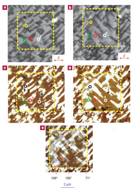
Among these single-phase materials, BiFeO3 shows the ME effect
ob-served by T. Zhao, et. al. in microscope view, which means that the configuration of micro/nano-scale ferroelectric or ferromagnetic domains changed by an applied magnetic or electric field [45].
The working temperature range makes difficult the practical applica-tion of this single phase materials for common applicaapplica-tions, because most of them can work only at very low temperature [28] and the magnetoelectric co-efficient drops to zero as the temperature reaches the transition temperature [38].
Fig. 1. 1 Direct ME effect of single-phase TbMnO3: Electric polarization induced by an
Fig. 1. 2 Converse ME Effect of BiFeO3: magnetization changed by an applied electric
field. (Reported by T. Zhao, et al, Nature Materials, 2006) [41]
1.2.4 ME effect in composite materials
The ME effect in composite materials is known as a product tensor property, which is the product of a magnetostrictive and piezoelectric com-pound [46]. Thanks to the micromechanical coupling, an applied electric field induces a magnetization via the micromechanical coupling between the constituents, or an applied magnetic field induces strain in the magnetostric-tive constituent which is passed on to the piezoelectric constituent and in-duces an electric polarization [1].
For the piezoelectric composites, there are some common connec-tivity proposals such as 1-3-type fiber composites with fibers of one phase embedded in the matrix of another phase, 0-3-type particulate composites made of piezoelectric and magnetic grains embedded in piezoelectric matrix and 2-2-type laminate composites including piezoelectric and magnetic layers, which are shown in Fig. 1. 3.
Fig. 1. 3 Schematic illustration of three common types of bulk composites (a) 1-3 fi-ber/rod composite, (b) 0-3 particulate composite, (c) 2-2 laminate composite [18]
After first proposed concept of the ME composite in 1972 by van Suchtelen, the ME effect in bulk composites have drawn ever-increasing in-terest [18].
Tab. 1. 1ME voltage coefficient for some bulk composites materials [20, 28, 47-58].
Composite
ME voltage coeffi-cient αE
(mV/cm.Oe) Ceramic
Composite (0-3) CFO/ BTO 50 @ fr
(0-3) NZFO/PZT 155@ 1kHz (2-2) NCZF/PZT/ NCZF 782 @1kHz Ceramic-Alloy Composites (2-2) Terfenol-D/PMT-PT 10.3×10³ @1kHz (2-2) Terfenol-D/PVDF 1.43×10³ (2-1) FeBSiC/PZT-fiber 22×10 3 @ 1Hz and 750×103 @ fr (2-2) FeBSiC/PVDF 21.46×10³ @ 20Hz (2-2) FeCoSiB/AIN 3.1×10 3 @ 1Hz and 737×103 @ fr Polymer-based Composites (2-2) PZT in PVDF/Terfenol-D in PVDF 80 @ 1kHz and 3× 10³ @ fr
(1-3) Terfenol-D in epoxy/PZT 500 @ 100Hz and
18.2×10³ @ fr
(0-3) CFO/P(VDF-TrFE) 40 @ 5kHz
BTO: BaTiO3; CFO: CoFe2O4; NZFO: Ni0.8Zn0.2Fe2O4; NCZF: Ni0.6Cu0.2Zn0.2Fe2O4;
AIN: aluminium nitride; PMN-PT: Pb(Mg,Nb)O3-PbTiO3; PVDF:
polyvinylidene-fluoride; P(VDF-TrFE): poly(vinylidene fluoride-trifluoroethylene); fr:
electrome-chanical resonance frequency.
However, most of the theoretical works were undergone which pro-vided quantitative understanding of the ME effect in bulk ceramic composites [20]. ME voltage coefficient of some bulk composites materials at certain frequency have been listed in Tab. 1. 1. The ME effect obtained in
compos-ites is more than a hundred times that of single-phase ME materials and is know as a product tensor property, which is induced by the cross interaction between different ordering of the two phases in the composite.
Coupling between the constituents of laminated double-, triple- or multilayer composites can use glue and epoxy. In layered magnetostric-tive/piezoelectric composites, direct ME effect is generated through the mag-netic-field induced strain of the magnetostrictive layer which is mechanically coupled to the piezoelectric one subjected to stress variations; this latter transduces the stress to a voltage through its electromechanical conversion ability [1]. The ME coupling in a two-layer structure have been widely stud-ied by several groups who proposed models for ME effect and prediction of ME coefficient [32, 59]. Strictly speaking, the concept of product property between magnetostriction and piezoelectricity clearly corresponds to a ME coupling arising from the combination of two non ME Phases. It has been shown that the efficiency of the micromechanical coupling plays a crucial role. S. Dong investigated a laminate composite made of magnetostrictive Terfenol-D (TbxDy1-xFe2) and piezoelectric (Pb(Zr1-xTix)O3) layer. ME effect
of L-L mode (longitudinal magnetized / longitudinal polarized), T-L mode (transverse magnetized / longitudinal polarized) and T-T mode (transverse magnetized / transverse polarized) have been investigated experimentally in [60], in which the maximum ME voltage coefficient 86 mV/Oe under a bias of 500Oe has been got. It was also found that, the ME voltage output can be
increased by 101-103, when the composite sample operating at the
electrome-chanical resonance frequency. It has been shown that laminated composites operated under resonance frequency exhibit ME responses that are orders of magnitude larger than those acquired in single-phase material.
The ME effect in the single piezoelectric phase can not compare with the remarkable ME effect of composites of both magnetic and piezoelec-tric phases. Thus, ME effect, a coupled magnetic phenomenon via elastic in-teraction, is a result of the product of the piezoelectric effect
(mechani-cal/electrical effect) and the magnetostrictive effect (magnetic/mechanical ef-fect), which can be denoted by Eqs.(1.6) and (1.7) and shown in Fig. 1. 4. Details of composite microstructure includes: component phase properties, volume fraction, grain shape, phase connectivity, etc.[61].
Electrical Mechanical Mechanical Magnetic effect MEH = × (1.6) Magnetic Mechanical Mechanical Electrical effect MEE = × (1.7)
For the direct MEH effect of a composite, the magnetic phase
changes its shape magnetostrictively, when a magnetic field (H) is applied to a composite. Strain induced by this applied magnetic field, passed on to the piezoelectric phase, where an electric polarization appears. While, the
con-verse effect, MEE, is also possible to be put into application, in which applied
electric field (E) on the piezoelectric material produce sample’s strain, which can transferred as stress applied to the magnetostrictive material, inducing a
magnetization change (ΔM) or domain reorientation through the
piezomag-netic effect [1]. Thus, the ME effect in composites depends on the composite microstructure, and coupling interaction across magnetic-piezoelectric inter-faces [18]. In addition to their high ME coefficient, the laminated magneto-electric composites have a relatively simple fabrication method and structure. Extensive researches have been conducted on the ME effect because of the obvious potential of the coupling between magnetic and electric prop-erties of matter for its technical applications. Then, researchers have made considerable progress towards experimental and theoretical work on ME, and the state of the art in research on the electrodynamics of ME media was summarized in a book written by O’Dell in 1970 [62].
Fig. 1. 4 Schematic illustration of two types of ME effect in laminate composites (a)
MEH effect (b) MEE effect [63]
However, a general weakness of the ME effect that there was limited number of compounds within it and a limited understanding of microscopic sources of ME behaviour, restricted its useful application and caused a de-cline of research interest for about two decades. Recently, an impressive re-vival of the ME effect appeared and some major research topics and trends have been proposed for the future developments. One of these topics con-cerns structural ME effects in composite materials which contains two or
more constituents. And, the second major topic is associated to multiple (anti-) ferroic ordering [1].
1.2.5 ME coupling as a product property using Lorentz force
effect
Very recently, a ME effect based on the product property between Lorentz forces and piezoelectricity has been proposed [64-66]. The ME re-sponse triggered by this specific product property may be interesting for ap-plications in ME transducers and sensors. The previous but recent results about this particular ME coupling are presented in the following.
1.2.5.1 Magnetostrictive/piezoelectric laminate composites
The dc magnetic field response of magnetostrictive/piezoelectric magnetoelectric laminates driven by Lorentz force was reported by Jia and co-worker.
Fig. 1. 5 Magnetostrictive/piezoelectric laminate composite [64]
As shown in Fig. 1. 5, the composite consists of one L-T mode ME laminate and one ac current source supplying ac electrical current to Ter-fenol-D (TeD) alloy strips. Ac current is applied through the two conductive magnetostrictive TeD layers only to induce Lorentz forces within them, in
the presence of the dc magnetic field Hdc. These Lorentz forces induce stress
and strain to the piezoelectric PMN-PT layer sandwiched between the TeD I
Ac Lorentz forces Piezo single
Crystal PMN-PT
pling through magnetostriction phenomenon. The Lorentz forces induced ME effect permits dc magnetic field detection along direction 2 and have addi-tional ability to ac field sensing in the direction 1 (L-T mode) using
magne-tostriction [64]. Researchers got ME coefficient: 6 μV/Oe.A at 1 kHz.
How-ever, it requires ac current supply on the electrically conductive Terfenol-D strips.
1.2.5.2 Brass ring around PZT disk
As shown in Fig. 1. 6, a composite consisted of a brass ring and a PZT disk. The ac current was applied circumferentially through the ring. By using the Lorentz force effect from metal strips in the magnetic field when applied with an ac current, the detection of dc magnetic fields can be
achieved with a ME coefficient 3.3 μV/Oe.A at 1 kHz [65]. Similarly with
previous configuration, the ac current source was also needed.
Fig. 1. 6 A ME composite of a brass ring and a PZT disk with Cartesian coordinates [65]
1.2.5.3 Crystal PMN-PT between two aluminium strips
In the work of Leung C.M et.al., an ac current was applied through the strips. Then, the direct coupling of the Lorentz force effect appeared in the aluminium strips in response to a dc magnetic field under an ac electric current with the transverse piezoelectric effect in the PMN-PT plate [66],
which was shown in Fig. 1. 7. The measured ME coefficient was 23 μV/Oe.A
at 1 kHz.
Radial Lorentz forces I
Fig. 1. 7 A dc ME sensor in the Cartesian coordinate system proposed by Leung C.M.
et. al. [66] F1 are Lorentz forces transversely applied to the piezoelectric PMN-PT
plate
1.2.6 Applications
Extensive research has been conducted on the magnetoelectric materials, due to their important technological applications as multifunctional devices such as magnetic field sensors for detecting ac or dc fields (thus complementing Hall sensors and current measurement probes), transducers in microwave electronics which converts the microwave magnetic field into a microwave electric field, actuators, data storage applications and so on [1, 34, 55, 67]. Their transductions properties of ME effect could be used in electromagnetic pick-ups and recording heads [28].
For instance, the multiferroic composite thin films could be developed as a magnetoresistive (MR) sensors through their direct ME response [20], in which a constant dc current I is required to detect its
resistance ΔR by a read signal of a voltage amplitude change based on the
equation ∆ = × ∆V I R, where ∆R senses the magnetic field change. Thus, the
dc test current flow is through the sensor stack in order to measure its change in resistance (i.e. amplitude response signal) as a function of the fringing magnetic flux of the recorded bits, when the reader moves along the recorded track [68]. Vopsaroiu et al. proposed a novel magnetic recording head based
on the magneto-electric effect in laminated multiferroic materials, which was much simplified in terms of sensor construction [68]. Their design principle
was based on ∆ = ×V α δH, where δ denoted the stray magnetic field of H
the record bits. In comparison with former magnetic recording read head (MR) technology, it produced a voltage response without the need for a test current.
Fig. 1. 8 Magetoelectric laminte composite using TERFENOL-D and PZT discs. (a) Schematic structure; (b) photograph of the sample [38]
Ryu J. and his research group have done extensive research on ME materials for magnetic field sensing and current measurement probes in high-voltage electric transmission systems. As shown in Fig. 1. 8, they investi-gated a piezoelectric-magnetostrictive composites which were prepared by
stacking and bonding Pb(Zr, Ti)O3 (PZT) and Terfenol-D disks, from which a
high ME voltage coefficient of 4.68V/cm.Oe was obtained at room tempera-ture [38].
(a)
Furthermore, they may find applications in memory devices, due to their hysteretic nature of the ME effect, and because of the shift in the resonance frequency in a static magnetic or electric bias field the composite materials hold promise in electrically tunable microwave applications such as filters, oscillators, phase shifters [69].
1.3 Electrostrictive effect
1.3.1 Electroactive polymers (EAP)
Electroactive polymers (EAP) are the polymers that change size or shape in response to electrical simulation. EAP materials with electrome-chanical properties are of great interest in many fields of acoustics where they are used in a large number of applications including loudspeakers, ultra-sonic transducers, sonars, actuators and dust-wiper [70]. The impressive ad-vances in improving their actuation strain capability are always attracting the attention of scientists and experts from many fields [71-74]. Other potential applications include interactive tactile Braille readers for the blind and artifi-cial muscles shown in Fig. 1. 9 that can be used to mimic the movements of human, animals and insects for making biologically inspired robots and me-chanical devices [71, 75]. As listed in the (Tab. 1. 2 ), the EAP can be classi-fied into two major groups including: ionic EAP (involving mobility or diffu-sion of ions and their conjugated substances) and electronic EAP (which are driven by electric field or coulomb forces).
Fig. 1. 9 EAP gripper grabs rocks and works as artificial muscle [76]
Tab. 1. 2 List of the leading EAP materials [77, 78]
Electronic EAP Ionic EAP
Dielectric EAP
Electrostrictive graft elastomers Electret polymer
Electrostrictive paper Electro-viscoelastic elastomers
Ferroelectric Polymers Liquid crystal elastomers (LCE)
Ionic polymer gels (IPG)
Ionic polymer metal composite (IPMC) Conductive polymers (CP)
Carbon nanotubes (CNT)
• Ionic EAPs: Their actuation is caused by the displacement of ions inside the polymer. Only a few volts are needed for actuation, but the ionic flow implies a higher electrical power needed for actuation, and energy is needed to keep the actuator at a given position. Examples of ionic EAPS are responsive gels, ionic polymer-metal composites (IPMCs), and conductive polymers. Yet another example is a Bucky gel actuator, which is a polymer-supported layer of polyelectrolyte material made of an ionic liquid sand-wiched between two electrode layers consisting of carbon nanotubes [77].
• Electronic EAP: Their actuation is caused by electrostatic forces between two electrodes and/or interaction between dipoles inside the the ma-terial, squeezing the polymer. Electronic EAP require no electrical power to keep the actuator at a given position. Electrostrictive polymers and dielectric elastomers are the leading electronic EAP [71].
Thus, there are several kinds of electroactive polymers and the shape change mechanism is somewhat different in case of different types [79]. For many decades, it has been known that some types of polymers can change shape in response to electrical stimulation. As shown in Fig. 1. 10, when sub-jected to a voltage, dielectrics may become thinner due to their electrostric-tive properties [80]. At the very beginning of research on EAP, the studied materials were capable of producing only a relatively small strain. However, since the beginning of the 1990s, some newly developed EAP exhibited large strain [78]. Generally, strain generated by EAP can be as high as two orders of magnitude greater than the rigid and brittle piezoelectric ceramics.
Fig. 1. 10. Different types of deformation of dielectrics [80]
(a) A nonpolar dielectric without applied voltage; (b) Subjected to a voltage, dielectrics become thinner
1.3.2 Basic properties of electret
An electret, a solid dielectric with a quasi-permanent electric mo-ment, can exhibit an external electric field in the absence of an applied field [81]. As early as 1919 Japanese navy Captain Kawao Wantachi had been able to create an artificial membrane by mixing beeswax with Brazilian palm gum (usually carnauba wax) and resin. The resulting material was then polarised in an electric field, and had maintained its charge for a long time afterward-resulting in the world's very first electret.
The original method, using dipolar polarisation with space charge is applicable to waxes and to polymers like Mylar [82]. Electron beam method (low-energy beams of about 20KeV in vacuum) was used for controlled charging and for research application from the 1960's to today [83]. Corona
method is preferred nowadays for industrial production, often applied at ele-vated temperatures [84]. Sessler G. M. and Gerhard-Multhaupt R. gave a de-tailed historical review of the research work performed on electrets [85, 86]. It showed that although heating, ac and dc current could be used as method to prepare the dielectric substance (or move the molecules) at the beginning, pure dc is always required to finally fix the charge.
At the microscopic level, electrets can be classified as real-charge electrets or dipolar-charge electrets [87]. Real-charge electret consists of in-jected or embedded charges within the dielectric, while dipolar-charge elec-tret is composed of permanent dipoles at the molecular level. Some dielec-trics are capable of storing both real and dipolar charges. The macroscopic shape of the electrets can be a film or fiber. Fig. 1. 11 shows the orientation of dipoles within electrets under applied electric field.
Fig. 1. 11 Orientation of dipoles under electric field [17, 87]
Dipolar-charged electrets can be formed by heating up the material, typically well above the glass transition temperature in the presence of a strong external electric field, and then cooling the material while the field is maintained, thus orienting the dipoles in a semi-permanent configuration. Real-charge electrets can also be formed by exposing the material to a charged plasma or corona.
The distribution of injected sites for real-charge electrets has been an active area of research [88]. The field of electrets has developed rapidly with an increasing number of materials, methods for investigation of
charge-storage phenomena, and the development of creative and exciting applica-tions ranging from air filters to microphones, as well as electrostatic re-cording, artificial muscle and electret motors and generators [7, 89, 90]. They are also considered for transducer applications, since they mimic piezoelec-tricity by their unusual electromechanical properties [91].
1.3.3 General concepts of Electrostrictive effect
Generally, electrostriction is defined as quadratic coupling between
applied electrical field and strain. The strain Sij and the electric flux density
Dm are expressed as:
ij n mnij n mn m m n mnij ij E ijkl ij T E M E D E E M T s S 2 + = + = ε (1.8)
where sijkl, Tij, Mmnij and εmn are the elastic compliance coefficient,
stress, electric field related electrostriction coefficient and linear permittivity respectively [92]. Em and En are the electric field intensity. In our work, we
focused on the electrical field induced thickness strain S3 for a non stressed
and low thickness film[93]. In this case, the expression of strain and electric flux density is simplified as:
2 3 3 3 33 3 3 33 3 2 33 3 3 S s T M E D
ε
E M E T = + = + (1.9)Two phenomena named “electrostatic” (Maxwell stress effect) and “electrostriction” are involved in the electrostrictive induced strain [94]. As a
consequence, the electrical field related electrostrcitive coefficient M33 can
*
33 Maxwell electrostrictive
M =M +M (1.10)
where, MMaxwell, named as Maxwell stress, is a well-known quantity
that results from the electrostatic interaction between two surfaces charged with opposite charges. In the case of a thin film of polymer material, if a voltage is applied in order to create an electric field in the thickness direction of the film, this voltage will generate charges of opposite signs on the two surfaces of the film perpendicular to the thickness direction [96]. This creates an attraction between the two surfaces which results in the deformation of the film. The corresponding stress-Maxwell stress, is related to the square of the electric field, and is therefore a quadratic effect analogous to electrostriction, but one should realize that Maxwell stress is an external effect, independent of intrinsic electromechanical properties of the material such as the ones rep-resented by the electrostrictive coefficients. Nonetheless, this external effect needs to be taken into account in the analysis, because it will contribute to the deformation of the film in exactly the same manner as the electrostrictive effect.
Generally, the relation between the strain and an applied electric field for the electrostrictive materials can be described according to [97, 98]:
2
3 33 3
S =M E (1.11)
where E3 is the applied electrical field, and M33 is the the
electro-strictive strain coefficients. Consequently, M33E32 represents the strain
in-duced by the electrostriction. For a linear dielectric, M33 is equal to Q33ε02(εr
-1)2 where Q33 is the electrostrictive coefficient, and ε0 and εr are the
free-space permittivity and the relative permittivity of the tested sample respec-tively.
In addition to the true electrostrictive contribution (M33E32), one
and an apparent electrostrictive coefficient M33* is very often employed [99].
In the case of thickness strain, this additional contribution is assumed to equal to –(εr.ε0 /Y) E32. Finally M33* can be written as:
(
)
2 * 2 0 33 33 0 1 r r M Q Y ε ε ε ε = − − (1.12)Moreover an empirical relationship between the electrostriction co-efficient, the permittivity, and the elastic constant has already been
estab-lished [95], suggesting that the apparent M33* coefficient should be
propor-tional to ε0(εr−1)²/(Y.εr).
1.3.4 Enhanced Electrostrictive performance of cellular
polypropylene electret
1.3.4.1 Researches on polypropylene (PP) electret
With the development of science and technology, the application of the foamed polymers has been paid the increasing attention. The functional materials which have high charge-storage ability and high piezoelectric sta-bility are necessary for the air filter, mechanical/acoustic transducers and the piezoelectric sensors [90].
Beyond the various available electrets, cellular polypropylene (PP) is a well known polymer for its ability to store electrical charge when sub-jected to the corona discharge and for having ferroelectric-like properties (i.e., remnant electrical field-induced polarization) caused by charged lens-like voids which are responsible for a strong anisotropy within the polymer. It has therefore been given the name ferroelectret [8, 9]. However, few stud-ies have been done on that how injected charge affects electromechanical performance of charged cellular PP electrets.
Because of their properties such as lightweight, non-toxic and low price, the commercial used cellular PP film, an ideal electret which can be defined as “Electronic EAP” was researched by a number scholars in recent years. In [9], it was studied by an acoustic method and dielectric resonance spectroscopy. The light emission from barrier discharges in this electret was also quantitatively studied by Qiu X. et. al. [100]. Besides, FTIR analysis was carried out by Sellin N. et. al., in order to analyze the chemical structure changes of PP caused by corona treatment. Furthermore, they analyzed the charged samples by infrared spectroscopy (FTIR/ATR) and atomic force mi-croscopy (AFM) techniques [101].
The pressure expanding treatment and the chemical modification has been applied to cellular polypropylene in order to improve its charge storage stability and the piezoelectricity [102]. As shown in Fig. 1. 12, a scanning electron microscope (SEM) image of PP, the closed-cell voids in-side cellular PP have a vertical dimension of several micrometers and a lat-eral dimension of tens of micrometers [100]. The open-circuit thermally stimulated discharge (TSD) current spectra were studied systematically in [14] as well. At the same time, energy traps inside of polymers have been ana-lysed exactly for the chemically modified cellular PP.
In order to enhance the electret properties, chemical treatment has
also been used to cellular PP films in [14]. A mixture solution of H2SO4,
CrO3 and H2O and fluorination in a hydrofluoric acid has been applied during
the treatment procedure of cellular polypropylene films. M. Wegener et al. pointed that the voids size inside of cellular PP can be increased by the infla-tion treatment. Thus, the macroscopic dipoles in samples are going to become
larger. The inflated samples have shown the excellent d33 piezoelectric
coef-ficients [11, 103]. And when temperature of cellular polypropylene is rising up to 60°C, the piezoelectricity activity is decreased [8, 104].
Fig. 1. 12 SEM image of cellular PP after pressure expansion [14]
A simple model for the occurrence of piezoelectricity in polymers has been given in [105, 106]. The elastic behaviours of voids in cellular polymers when they are discharged by DC corona setup have been proposed. They have pointed that cellular polymers exhibit intrinsic (quasi) piezoelec-tricity. Besides, with the special charging process, the piezoelectric coeffi-cient of the cellular PP is much larger than some of ferroelectric polymers.
In summary, there have been many researches on enhancing piezo-electric properties of polypropylene electrets such as: expansion treatment, chemical modification and charging in gas atmospheres at high pressure [14, 106, 107]. However, little attention was paid to charge cellular PP at high temperature in order to enhance its dipole polarization and electromechanical performance.
1.3.4.2 Basic principles of corona charging technique
Atmosphere corona discharge can enhance the adhesion ability of the polymers and has been extensively applied in photocopiers, electrostatic precipitators, and indoor air cleaners for decades [108-111]. Electron ava-lanche occuring in the procedure of corona phenomenon is shown in Fig. 1. 13. In application of the electret microphones, preparing the polymer foils by the corona discharge technique has been applied widely [112]. New applica-tions of corona poling have been emerging recently, for example ozone
pro-duction, surface processing, as well as polymer surface treatment [113]. It is a useful technique that can increase adhesive performance, inject real charge into the films and form macro-dipole within them [114]. Their results of co-rona-discharge show that this surface treatment of polymer film can lead to dramatic increase in the polar and adhesive character of the surface. Other re-searchers also report that the corona discharge will not only increase the polymers’ surface energy, as well as their hydrophilic character, but also generates polar functional groups and the cleavage of chemical bonds [115]. However, the power loss, the generated ozone, the audible noise and electro-magnetic interference of corona became main problem in some special occa-sion, such as over-head high-voltage electric power transmission line [108, 109, 111].
As shown in Fig. 1. 13, during the procedure of corona discharge, the air around vicinity of the cathode is ionized and excited. Meantime, the negative charges and electrons are driven to the anode, obtained by the sur-face layer of the polymer, and generate new chemical bonds [116].
Fig. 1. 13 Development of the negative electric charge avalanche from the cathode [108, 117].
A drawback of the setup shown in Fig. 1. 13 without grid electrode is the relatively large lateral non-uniform charge distribution and thus, the
Grounded electrode Discharge electrode Negative electric charge Positive electric charge
surface potential could not be controlled as we expected. Thus, in our corona poling experiment, the sample is exposed to a high-voltage in a point-plate arrangement. A grid is inserted between the needle and sample, and the back electrode under the sample is grounded. Such corona poling setup can gener-ate both volume and surface charges. During poling procedure, the surface potential can be regulated by the inserted metallic grid. And the maximum surface potential roughly equals to the applied potential of the grid. This is a simple and speed charging method.
There are two charging techniques, contacting electrodes method and corona discharge method, which are the conventional methods which can be employed to orient dipoles and build up charges inside polymers. The charging method used in our research is corona poling. On the other hand, there are negative and positive corona discharge methods whose working mechanisms can be concluded as followings: There are the sharp distinctions on the secondary electron processes. The number of electrons in negative co-rona poling is an order of magnitude greater than that in the positive coco-rona poling; the negative corona generate more ozone and less audio noise and electromagnetic interference; negative corona discharge has lower onset fields and higher breakdown voltage than positive corona, thus decrease the need of insulation of the setup [118-120]. In addition, the investigations car-ried out by Yovcheva T.A et al. show that for negative corona charged sam-ples, the oxygen content generated after poling was approximately 2.4 times higher than that in positive corona poled films [121]. Due to the different mechanisms of the positive and negative corona discharge, only the negative corona poling treatment is discussed in our works.
1.3.4.3 Charge storage mechanisms of polymeric electrets
From an applied point of view, it is important to analyze the surface charges storage ability of the polymer after negative corona discharge. Charges stored in polymer electrets could be composed by surface charges
and injected charges which are captured by traps distributed on the surface and in the electret’s volume. According to [122], the charge storage capabil-ity of an electret polymer film is mainly determined by its chemical nature. For semicrystalline polyolefines, the lamellarcrystals embedded in the amor-phous matrix form a heterogeneous morphology, where charge trapping and transport mechanisms depend on the crystallinity. The shallow traps are lo-cated in the peripheral and surface layer of the electret film, whereas charges in higher release energy traps are deposited in the central region of the spherulites [123, 124]. There are a number of factors that have effect on the charge storage ability and dipole orientation of polymeric electrets such as chemical impurities, inside voids structure, surface roughness condition, macro-molecular arrangements, particles added in the polymers, chemical composition, discharge conditions (needle and grid voltage, charging time and temperature etc.) and metal electrode spurred on the surface of the elec-trets etc..
In Ref.[125], the researchers pointed out that the magnitude of the surface voltage on the polymer films due to the corona discharge, associated with charge retain ability, was a function of the strength of the applied volt-age to the corona needle, the time relative to the voltvolt-age application, and the temperature. According to [126], the results also show that charging poly-mers at a relative high temperature dramatically increases their charge stabil-ity. As the charging temperature is increased, one tends to fill deeper traps because of changes in relative capture and escape probabilities. Besides, the influence of high humidity and porosity on the surface-charge decay and sta-bility was investigated in [127, 128]. The effect of the samples’ roughness on the charge stability has been mentioned in [5], but experimental results were not presented their piece of work. In order to explore the application poten-tial of such polymers, this paper gives, for the first time, the numerical re-sults under different charge conditions.
![Fig. 1. 1 Direct ME effect of single-phase TbMnO 3 : Electric polarization induced by an applied magnetic filed [42]](https://thumb-eu.123doks.com/thumbv2/123doknet/14528808.723259/27.892.154.743.497.895/direct-effect-single-electric-polarization-induced-applied-magnetic.webp)
![Fig. 1. 3 Schematic illustration of three common types of bulk composites (a) 1-3 fi- fi-ber/rod composite, (b) 0-3 particulate composite, (c) 2-2 laminate composite [18]](https://thumb-eu.123doks.com/thumbv2/123doknet/14528808.723259/29.892.193.698.575.958/schematic-illustration-composites-composite-particulate-composite-laminate-composite.webp)

![Fig. 1. 9 EAP gripper grabs rocks and works as artificial muscle [76]](https://thumb-eu.123doks.com/thumbv2/123doknet/14528808.723259/39.892.291.609.131.337/fig-eap-gripper-grabs-rocks-works-artificial-muscle.webp)
![Fig. 1. 13 Development of the negative electric charge avalanche from the cathode [108, 117]](https://thumb-eu.123doks.com/thumbv2/123doknet/14528808.723259/47.892.200.718.643.890/fig-development-negative-electric-charge-avalanche-cathode.webp)