HAL Id: hal-01509857
https://hal.archives-ouvertes.fr/hal-01509857
Submitted on 18 Apr 2017
HAL is a multi-disciplinary open access archive for the deposit and dissemination of sci-entific research documents, whether they are pub-lished or not. The documents may come from teaching and research institutions in France or abroad, or from public or private research centers.
L’archive ouverte pluridisciplinaire HAL, est destinée au dépôt et à la diffusion de documents scientifiques de niveau recherche, publiés ou non, émanant des établissements d’enseignement et de recherche français ou étrangers, des laboratoires publics ou privés.
Distributed under a Creative Commons Attribution - NonCommercial - NoDerivatives| 4.0 International License
Title: Dynamic Tool Center Point (DTCP)
implementing in Automated Fiber Placement (AFP)
Itzel de Jesus Gonzalez Ojeda, Olivier Patrouix, Yannick Aoustin
To cite this version:
Itzel de Jesus Gonzalez Ojeda, Olivier Patrouix, Yannick Aoustin. Title: Dynamic Tool Center Point (DTCP) implementing in Automated Fiber Placement (AFP) . the third International Symposium on Automated Composites Manufacturing (ACM1) , Apr 2017, Montreal, Canada. �hal-01509857�
COVER SHEET
NOTE: This coversheet is intended for you to list your article title and author(s) name only —this page will not print with your article.
Title: Dynamic Tool Center Point (DTCP) implementing in Automated Fiber Placement (AFP) for Proceedings of the Proceedings 3rd International Symposium
on Automated Composites Manufacturing (3rd ACM)
Authors: Itzel de Jesus Gonzalez Ojeda Olivier Patrouix
Yannick Aoustin
PAPER DEADLINE: **January 15, 2017** PAPER LENGTH: **8 PAGES MAXIMUM ** SEND PAPER TO: Professor Suong V. Hoa
E-mail: [email protected]
Please submit your paper in Microsoft Word® format or PDF if prepared in a program other than MSWord. We encourage you to read attached Guidelines prior to preparing your paper— this will ensure your paper is consistent with the format of the book and/or CD-ROM. Final book will print in Black ink only and color art is acceptable for the CD-ROM, DEStech will change picture files to grayscale for book (if possible).
--
NOTE: Sample guidelines are shown with the correct margins. Follow the style from these guidelines for your page format. Hardcopy submission: Pages can be output on a high-grade white bond paper with adherence to the specified margins (8.5 x 11 inch paper. Adjust outside margins if using A4 paper). Please number your pages in light pencil or non-photo blue pencil at the bottom. Electronic file submission: When making your final PDF for submission make sure the box at “Printed Optimized PDF” is checked. Also—in Distiller—make certain all fonts are embedded in the document before making the final PDF.
ABSTRACT
In the last years, the robots have been implementing in the task that were previously performed specialized machines such as polish, milling, placement of fibers, among others. However, the implementation using industrial robots for these applications has accuracy problems due to the flexibilities within the robot arm or the tooling when external forces are applied. This paper is an introduction of the work done to improve the precision in the robotic fiber placement, taking into in account the deformation in the compaction roller.
Keywords: Automatic Fiber Placement (AFP), model elastic-static, model order
reduction (MOR), dynamic tool center point (DTCP)
INTRODUCTION
The industrial robots are designed for simplifying repetitive process, they give a flexibility to the industrial application. The serial robots used in industrial applications like: fiber placement, milling, polish, turning, drilling… do not have the required precision compared with a tool machine [1].
The principal goal in our work is improve the robot’s precision without stopping the productive processes in our special case for the Automatic Fiber Placement (AFP). In order to improve robot’s precision, we must know the flexibility (or stiffness) of robot and external elements, to adapt the correction [2]. The AFP is the automatic application of pre-impregnated fiber or individual dried fibers [3]. The process of AFP needs to compact the fibers for removing air, to assure the homogeneity and guarantee a good contact between the ply [4]. A compaction roller applies the compaction forces. It is made of highly deformable material that affects the definition of Tool Center Point (TCP). The fiber placement task is a force based task. On flat surfaces the TCP could be kept constant. However on a piece with corners or complexes curves, the compaction roller deformation creates a difference between the TCP and the contact.
____________
Itzel de J. GONZALEZ O.12 [email protected],
Olivier PATROUIX. ESTIA1[email protected]
Yannick AOUSTIN2[email protected]
1 ESTIA, ESTIA-Recherche, Technopole Izarbel, 64210 Bidart, France.
This difference creates disturbances on application of fibers. This changes are linked to the interaction between the force and the surface. Our approach is to perform Finite Elements Analysis (FEA) modeling of the roller under load to obtain the roller behavior when it is in contact with a mold. The problem with FEA simulation is the computation time which is not compatible with robot control. So we propose a strategy to transfer this information based on model order reduced (MOR). The applied force can be measured by a force sensor in real time, the deformation can be calculated thanks to MOR. The TCP can be corrected so we propose a Dynamic TCP (DTCP).
The industrial robots have a closed internal control. So all characteristics of robot are not accessible or modifiable for warranty issues [5]. To achieve our goal, we need to add an external loop. This loop is a sensor- based control one. It takes into account the interaction between robots and environment (external forces) [2, 5].
The paper is outlined as follows, the section materials and models, the section proposal, the section experimental and results and the section the conclusions and perspectives.
MATERIALS AND MODELS
Materials
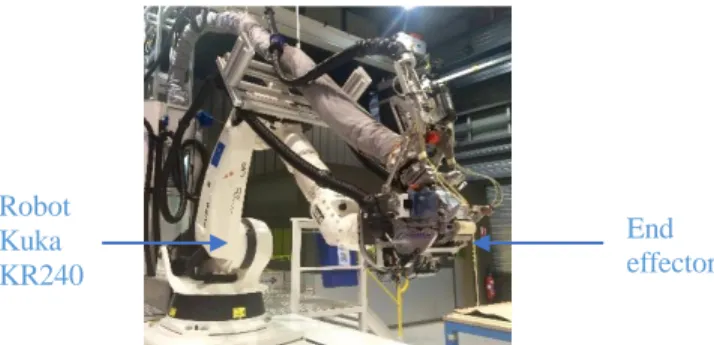
The robotic cell at CompositAdour has eight DOF. It is composed of a serial robot KUKA KR 240 (six DOF) mounted on a linear rail (one DOF) and a vacuum table or a steel mold for draping (one DOF). The robot integrates a special end effector for the fiber placement (Figure 1). This is composed of a heating system (laser or infrared light), a compaction roller, a cutting system and the wicks guide system.
Figure 1 Robotic Cell at CompositAdour
Industrial problem
The placement fiber process uses an important compaction force. The compaction force (Fz) range is between 0 and 1200 N according to the fiber’s type and it must be normal to the surface (Figure 2).
According to the manufacture specification of fiber placement, the fiber can be taped in the next angles 0°, 45°, 90° and 135°. In the complexes surfaces, the compaction roller is not in full contact, when the fiber taped has an angle of 45° or 135° (Figure 2). To pass corners in the mold, a rotation of the tool to tape the next point in the trajectory is needed. This rotation must respect the constraint of the force (normal to surface). The compaction force is supposed to be distributed on the roller height, if it is not the case then, the end effector has unwanted effects (slippage or rotation). This impact the quality of the manufactured part.
Robot Kuka KR240
End effector
Figure 2 Force normal to the surface
Flexibility modeling
The robot dynamic model allows to take into account the robot’s flexibility and external forces [2, 6]. Usually on industrial robots for flexible modeling, we consider the robot’s link as rigid body and the flexibilities located at the joint. However this model cannot be implemented in an industrial controller without warranty issue. For AFP, we consider the flexibility at the tool: compaction roller.
Compaction roller modeling in FEA
The flexibility in a compaction roller generates errors during the AFP, because it is not considered in the robot trajectory. The roller material is based on P-type Sylomer. The behavior laws to model this type of material are hyper-elastic ones. These laws have to be used for non-linear materials with large shape changes [7, 8]. We use the FEA software1 to simulate the roller. The hyper elastic materials can be simulated with the several models: Neo-Hookean, Mooney Rivlin, Gent, Odgen and Yeoh.
The roller material is not included in the material library. Then to estimate the model parameters, we use a characterization machine to compact real roller with a force between 0 to 800N. We use a range sensor to measure the deformation roller in the Z-axis. This experimentation allows us to know the behavior stress–strain in Z-axis of material. We decided to use the Odgen model because it gives the best results.
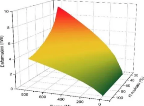
We compared the simulation results with the experimental ones to adapt the FEA parameters. Ones the model calibration is done, we can compute, from the simulation, information such as pressure, contact area, deformation in the roller... The FEA modeling allows us to perform simulations when the roller is partially in contact with the mold. The results for deformation of FEA modeling are presented in the Figure 3.
Figure 3 Deformation roller information for given force and height 1 ANSYS Workbench 15.0 Mold End effector Z Y X
Model order reduced (MOR)
The model order reduction technique is frequently used in multi-physical to reduce the complexity of models [9]. This allows to represent a solution of complex problem with a minimum information [10]. Our model is represented in equation (1) for deformation.
∆= 𝑓(𝐹, 𝐻) (1)
Where:
∆= Deformation roller height in contact with the surface
H= Compaction roller height in contact with the surface
F= Force
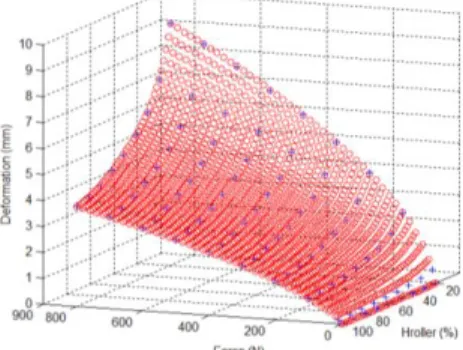
Our approach for the MOR is based on Neural Networks (NN) and the learning has been carried on using Matlab software. The result for deformation model is presented in the Figure 4. This model has a learning relative error 5x10⁻⁶ for deformation model
based on Mean Square Error (MSE). Ones can notice that the NN has the ability to interpolate between learning points.
Figure 4 Deformation model based neural network computation
The NN parameters can be exported and programmed in c# to cope with our experimental setup.
PROPOSAL
Modeling task
Generally in industrial applications, the manipulator arm components and the effector are considered rigid elements. Then the TCP is fixed to a position / orientation, because its geometry is fixed. However the compaction roller has a big deformation when it is under load. Then, we propose to take into account the deformation to improve the robot precision with a DTCP. We will be based on a force control (external hybrid control) to change the TCP.
The current definition of TCP, in the industrial robot controller, is sent to an external system. The compaction force is measured thanks to a force sensor by the external system so it can compute the deformation using the MOR. The deformation is added to the current TCP to get the new TCP and it is sent to the robot controller. The TCP is affected for the deformation.
External hybrid control
The roller deformation depends on the applied force and the compacting roller height in contact with the mold. As we cannot measure the roller height in contact in real time. We have chosen to estimate it using a robot position on the path (given by the forward kinematic model of the robot) and the off-line programming (based on CAD of the mold). The forces is measured using an ATI 6 DOF force/torque sensor. This sensor is placed between the flange of the robot and the end effector.
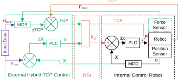
On our experimental setup based on kuka robot, the external hybrid control can be integrated on the controller using the RSI module (Remote Sensor Interface). The external hybrid control can be managed in Cartesian space. In Figure 5, we present the external hybrid control. The forces and torques are measured by sensor force. To transform the force measured (Fmes) in a TCP differential (∆TCPz) by the MOR and we
need to know the path contact (Hroller). The position-orientation (Xdes) desired is
compared to the position-orientation measured (X) and we get a differential position (∆X=Xdes-X). This differential is converted in through the position by the control law
(X). This position is send to inner position control by RSI module.
Internal Control Robot
External Hybrid TCP Control RSI
TCP Xdes 𝛤 Robot MGD q MOR + -In p u t D a ta PLC dX ∆TCP PLC ∆X X Force Sensor Position Sensor X X Xd Fmes + + Hroller + -TCP TCP
PLC: Position law control, Xd: Position-orientation desired in Cartesian space for the control position
loop. Γ: Vector of the torques of actuators; q: Vector of joints. Figure 5 External Hybrid Position/Force-Pressure Control
Robot calibration
The robot precision depends of its geometrical properties, the dynamic stability of the movements and the calibration of the TCP [11]. The calibration of TCP allows to know the position and orientation of each axis during the movement. The TCP must be modified, calibrated and defined in the controller of robot according to the tool geometrical characteristics.
EXPERIMENTAL AND RESULTS
Test environment
HARDWARE ARCHITECTURE
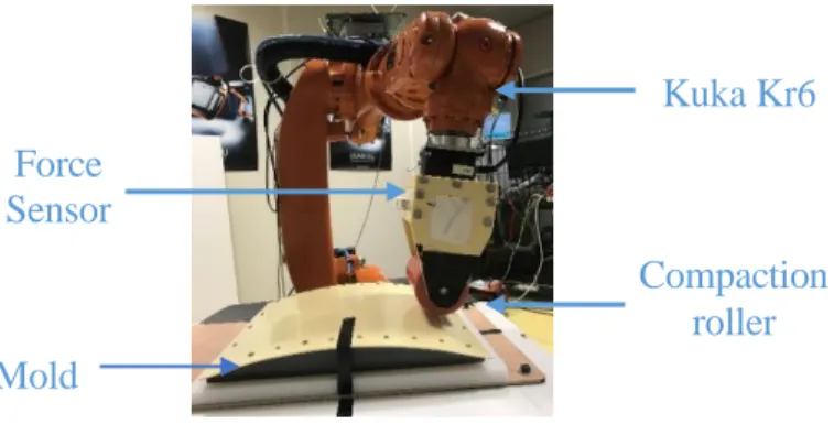
For our test, we use the robotic cell at ESTIA. This cell consists in a robot KUKA KR6 (Figure 6), a compaction roller, a mold and the RSI module which allows the communication between external system and the robot. The RSI module must receive data in a period of 12ms for KRC2 controller, otherwise data is lost. The input data for internal loop is a position of tool (X) and TCP. The KR6 and the KR240 have the same kinematic and use the same KRC2 controller so the results can be applied to the industrial cell.
Figure 6 Robot cell at ESTIA
Test procedure
The imprecisions in the robot trajectory are dues to the variation between the position of the tool and the piece [11]. There are different methods to measure the dimensional variations of the elements [12] and to modify the trajectory.
In a first experiment, we consider the TCP fixed and positioned on the roll surface and in the second the TCP changes along Z-axis according the calculated deformation. In the Figure 7, the robot path is described in XZ plan. Between the point B and C, the robot is in contact with the mold.
Figure 7 Procedure test
The robot goes to the position A with a joint space based trajectory and all the other movements are Cartesian space based trajectories. For (B→C) movement in order to get a compacting force, we have defined the positions B and C under the mold surface. The locations B and C are learned with force sensor monitoring to have a compacting force around 40N. The compaction roller is in full contact, then Hroller is equal a 100%.
The mold used has a curvature, then the point of the trajectory depends of the angle. To define the robot trajectory automatically, the information is get by CAD of mold. This information is computed in Matlab to get the points in the trajectory. The trajectory
starts in the angle -12° and finishes in the angle 12° with a step the 2° this angle is around Y-axis. Respecting the condition the perpendicularity between the Y-axis and the surface.
Results
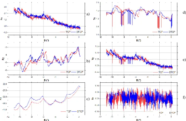
In order to make the results clearer. We decided to show the data collected between the angles from -12° to 0°. That it represented the information of half mold. The results are shown in Figure 8. In the Figure 8 a) and in the Figure 8 b) are showed the results for the force on X-axis (Fx) and for the force on Y-axis respectively, these forces
represent unwanted constraints during the translation along X-axis and Y-axis. In two cases, the trace is similar, but the Fx and Fy with a DTCP are slightly smaller than the Fx
and Fy with a static TCP. In the Figure 8 c) is showed the results measured in the force
Z (Fz). This force is equal to the force applied in the fibers along Z-axis. In this case, we
can see an important offset between the DTCP and the TCP. The force applied (Fz) with
a DTCP is generally smaller than the Fz with a static TCP.
Kuka Kr6 Compaction roller Force Sensor Mold
In the Figure 8 d), e) and f) are showed the torques measured around X-axis (Tx),
Y-axis (Ty) and Z-axis (Tz). These torques represent unwanted constraints around
X-axis, Y-axis and Z-axis respectively. The torques Tx and Ty with a DTCP is slightly
smaller than Tx and Ty with a static TCP. The Tz in two cases is almost null.
Figure 8 Result the force and torque to TCP
In a perfect case, the forces and torques have been equal to zero and the modification of the TCP is null. Although, the unwanted forces cause the slipping of the tool, they modify the position of the tool. The unwanted torques cause the rotation in the tool, they modify the orientation of the tool.
The results show in the Figure 8 demonstrated the DTCP reduce the unwanted forces and torques. Due to the force sensor limitation, we have tested a small force. If the force increases also the deformation. So the unwanted constraints (forces and torques) increases and so the offset between DTCP and TCP.
CONCLUSIONS AND FUTURE WORK
In industrial context, we cannot propose a solution which needs modifications to the industrial controller. To improve the robot precision in the AFP, we have implemented an external hybrid scheme. This implementation allows us to understand the origin of inaccuracies of the AFP.
On complex surfaces, the TCP orientation need to be changed, due to corners or the angles in the piece. It is very important to have the center of rotation set at the right place otherwise the rotation movement will create interaction forces or torques. These unwanted constraints will generate inaccuracy during the robot path. The compaction roller deformation creates a modification in the geometry tool and it produces a difference between the TCP and the contact patch. This difference creates disturbances (unwanted forces) and they cause slippage or rotation of the tool that affect the final
a) b) c) d) e) f)
piece. When the TCP is fixed the deformation is not take into account, then the unwanted forces increases. We have proposed the use of a MOR to compute the flexibility deformation in real time. The MOR is based on a Neural Network approach to approximate the FEA results. We have demonstrated that the forces and torques are decreased on complex surfaces when we take in consideration the deformations of the compaction roller for the TCP definition. We propose the use on a DTCP strategy which update the TCP values in the kuka industrial robot controller thanks to the RSI module. For future work, we are implementing a compaction pressure based task which involve a position/force-pressure control to guarantee the homogenous compaction when the contact patch changes. We are looking to use the MOR principle to compute the contact area, the pressure, according to measured force and CAD based roller height. The control scheme will be a DTCP in a position /force –pressure control one.
ACKNOWLEDGMENT
The authors would like to thank Pierre Joyot, Sthepanie Cagin, Julie Lartigau and Joseph Canou for their help and support in making this work possible. The authors would like to thank to CONACYT for the economic support.
REFERENCES
[1] G. Gallot, C. Dumas, S. Garnier, S. Caro, and B. Furet, "Correction dynamique de trajectoires pour l'usinage robotisé," presented at the 13ème Colloque National AIP PRIMECA, Le Mont-Dore, France, 2012.
[2] M. Makarov, "Contribution to modeling and robust control of flexible-joint robot manipulators - Applications to interactive robotics," Doctorat Sciences et technologies, Supélec, France, 2013. [3] A. Contreras. (2014, 28/07/2016). Tecnología de laminado automatizado en materiales
compuestos. Available:
https://materialsbreakthroughs.wordpress.com/2014/11/03/tecnologia-de-laminado/
[4] P. Parneix and D. Lucas, "Les matériaux composites en construction navale militaire,"
Techniques de l'ingénieur Applications des composites, vol. base documentaire : TIB140DUO,
2000.
[5] M. Uhart, "Amélioration de la précision du placement de fibres robotisé en utilisant un schéme de commande hybride externe force/vision," Doctorat Science, Institut de Recherche en Communications et Cybernétique de Nantes (IRCCyN), Université de Nantes, France, 2014. [6] W. Khalil and E. Dombre, Modélisation, identification et commande des robots, 2e édition revue
et augmentée ed. Paris, France: Hermes science, 1999.
[7] A. F. Bower, "Hyperelasticity – time independent behavior of rubbers and foams subjected to large strains," in Applied Mechanics of Solids, ed. USA: CRC Press, 2009, p. 820.
[8] R. Jakel, "Analysis of Hyperelastic Materials with MECHANICA – Theory and Application Examples –," in Presentation for the 2nd SAXSIM, Technische Universität Chemnitz, 2010, p. 72.
[9] W. Schilders, "Introduction to Model Order Reduction," in Model Order Reduction: Theory,
Research Aspects and Applications, W. H. A. Schilders, H. A. van der Vorst, and J. Rommes,
Eds., ed Berlin, Heidelberg: Springer Berlin Heidelberg, 2008, pp. 3-32.
[10] G. Bonithon, P. Joyot, F. Chinesta, and P. Villon, "Non-incremental boundary element discretization of parabolic models based on the use of the proper generalized decompositions,"
Engineering Analysis with Boundary Elements, vol. 35, pp. 2-17, 2011-01-03 2011.
[11] F. Shaopeng, "Advanced Techniques of Industrial Robot Programming," in Advances in Robot
Manipulators, E. Hall, Ed., ed: InTech, 2010, pp. 79-98.
[12] J. Schrimpf, " Sensor-based Real-timeControl of Industrial Robots," PhD, Department of Engineering Cybernetics, Norwegian University of Science and Technology, Norway, 2013.