HAL Id: cea-01743218
https://hal-cea.archives-ouvertes.fr/cea-01743218
Submitted on 27 Mar 2018HAL is a multi-disciplinary open access archive for the deposit and dissemination of sci-entific research documents, whether they are pub-lished or not. The documents may come from teaching and research institutions in France or abroad, or from public or private research centers.
L’archive ouverte pluridisciplinaire HAL, est destinée au dépôt et à la diffusion de documents scientifiques de niveau recherche, publiés ou non, émanant des établissements d’enseignement et de recherche français ou étrangers, des laboratoires publics ou privés.
Electrical properties of iron corrosion layers formed in
anoxic environments at the nanometer scale
Florence Mercier-Bion, Jiaying Li, Hélène Lotz, Ludovic Tortech, Delphine
Neff, Philippe Dillmann
To cite this version:
Florence Mercier-Bion, Jiaying Li, Hélène Lotz, Ludovic Tortech, Delphine Neff, et al.. Electrical properties of iron corrosion layers formed in anoxic environments at the nanometer scale. Corrosion Science, Elsevier, inPress, 137, pp.98-110. �10.1016/j.corsci.2018.03.028�. �cea-01743218�
1
Electrical properties of iron corrosion layers formed in
anoxic environments at the nanometer scale
Florence MERCIER-BION*(1), Jiaying LI(1), Hélène LOTZ(1), Ludovic TORTECH(2, 3), Delphine NEFF(1), Philippe DILLMANN(1)
(1) LAPA-IRAMAT, NIMBE, CEA, CNRS, Université Paris-Saclay, CEA Saclay 91191 Gif-sur-Yvette, France
(2) Sorbonne Universités, UPMC Université Paris 06, UMR 8232, Institut Parisien de Chimie Moléculaire (IPCM), 75005 Paris, France
(3) CEA Saclay, IRAMIS, NIMBE (UMR 3685), Laboratoire d'Innovation en Chimie des Surfaces et Nanosciences (LICSEN), 91191 Gif-sur-Yvette, France
*Corresponding author’s e-mail address: florence.mercier@cea.fr (F. Mercier-Bion).
Abstract
The electrical properties of the corrosion layers on archaeological iron artefacts were determined by Conductive Atomic Force Microscopy. Different corrosion products were studied: FeII carbonates, magnetite entrapped in the carbonate, and iron sulfides. The results indicate that the ferrous carbonate matrix is insulating, and that magnetite and iron sulfides have a conductive character, although these phases are not systematically connected to the metal. This suggests that electrons produced by the anodic dissolution of metal would be conducted to the external part of the corrosion product layer through a three-dimensional network of connected magnetite strips passing through the ferrous carbonate matrix.
Keywords: C-AFM; Iron corrosion; Electrical properties, Archaeological artefact, µRaman,
FESEM.
Introduction
In addition to studies concerning short-term corrosion processes (for example, steel
2
widely studied in recent years with two main objectives. The first, aims to predict the
corrosion of low alloy steel overcontainers for nuclear waste disposal [2-12]; the second,
concerns the domain of in situ preservation of archaeological remains buried in anoxic
carbonated soils [13, 14].
The iron corrosion anodic reaction involves the oxidative dissolution of metal into
ferrous ions. In anoxic water-saturated environments, the corrosion cathodic reaction
involving water reduction, or the reduction of H2CO3 or HCO3- according to the pH, can also
occur.
For all systems involving the corrosion of iron in carbonated anoxic medium, the
corrosion product layers show similar trends regarding the nature of the corrosion products:
primarily FeII carbonates, either siderite FeIICO3 or a mix of siderite and chukanovite
FeII2(OH)2CO3, with the occasional presence of iron oxides such as magnetite FeII,III3O4. This is
true for both century-long corrosion periods, as with iron archaeological artefacts corroded
over hundreds or thousands of years [7-9], or for iron coupons corroded in laboratory
experiments for just months, or years, under pressure and temperature controlled
conditions [4, 10-12, 15]. The presence of iron sulfides was also sometimes reported inside
the corrosion product layer (CPL) of iron artefacts corroded in natural carbonated anoxic
medium. This is probably linked to the presence of sulfate-reducing bacteria in deep anoxic
media. Fell et al. [16] showed, from transverse sections of several iron objects extracted
from waterlogged soil at the Iron Age Fiskerton site (Lincolnshire, UK), that iron sulfides
were contained in the outer part of the CPL. More recently, Grousset et al. [9] have
described the iron sulfides in the CPL of iron artefacts coming from different anoxic sites
(terrestrial or subaquatic). A diversity of iron sulfides was observed in the outer border of
3
formation of iron sulfides may be attributed to the presence of sulfate-reducing bacteria in
the burial environment.
Moreover, in the systems collected from the Glinet archaeological site (Seine Maritime,
France), widely studied for its anoxic environment [4, 6, 7, 17], in most cases, magnetite is
not directly connected to the iron metal. However, it is present underneath small strips and
nodules in the ferrous carbonate layer matrix constituting the CPL or underneath thick strips
(up to 200 µm) in the outer part of the CPL. This presence of magnetite connected to the
metal, enables the decoupling of anodic and cathodic corrosion reactions and subsequently
influences the corrosion behaviour (see below) and the way to model it.
Several authors [11, 18, 19] have focused their studies on the anodic reaction that is
always located at the metal/CPL interface. Corrosion studies involving the cathodic reaction
are less common. On the archaeological iron artefacts from the Glinet site, Saheb et al. [7]
(2011b) have highlighted, with reaction tracing based on the use of the Cu2+/Cu0 redox couple, the presence of Cu0 everywhere in the thick corrosion layer (200 µm). This observation suggests the consumption of electrons everywhere in the corrosion layer and
the decoupling of anodic and cathodic reactions. In several studies [14, 20], siderite is
considered isolating, although it is difficult to measure resistivity values, especially on
siderite formed due to iron corrosion. Magnetite is a semi-conductor that presents a low
resistivity of 5.62x103.cm [21] due to the possible electronic transfer between FeII and FeIII in its structure [22]. Thus, the electronic conduction in the layer could be caused by the
presence of this phase. Nevertheless, in most cases, this phase is present in the system in
the form of islets embedded in the carbonate matrix and does not seem to be electrically
4
transfer is the presence of a non-detected nanometre network of conductive phases
(probably magnetite), allowing the decoupling of anodic and cathodic reactions.
Considering all of these aspects, we wanted to gain a better understanding of the
potential location of the corrosion cathodic reaction by investigating the electronic
properties of the corrosion layers developed on artefacts from the Glinet site. For this
purpose, we used Conductive Atomic Force Microscopy (C-AFM), which is unique in its
capability to probe electrical characteristics with nanometre-scale resolution. Beforehand,
µRaman spectroscopy was performed for the identification of the crystalline nature of the
corrosion products.
Different corrosion profiles of the CPL were investigated: CPL constituted only by ferrous
carbonate, CPL of carbonates with the presence of magnetite in different morphologies, and
CPL of carbonates with the presence of iron sulfide phases, were also detected in the
examined samples. As for magnetite, the presence of these conductive phases in the CPL
could drastically change the corrosion behaviour of the system. That is why sulfides are also
considered in this study.
2. Materials and Methods
2.1. Samples
Two 500-year-old nails (GL12-72: 3 zones, GL07-35: 1 zone) from the Glinet
archaeological site (Seine-Maritime, France) were studied. After their excavation from the
anoxic carbonated site, the nails are preserved in ethanol (Ultrapur). All preparation steps
were carried out in an N2 glove-box: drying, epoxy-resin embedding, cutting and surface
5
transverse sections of these nails were analysed by the different techniques: µRaman
spectroscopy, Field-Emission Scanning Electron Microscopy (FESEM) and C-AFM.
2.2. Analytical techniques
µRaman Spectroscopy (µRS)
µRS measurements were carried out via an Invia Reflex® spectrometer with an
excitation wavelength of 532 nm. The laser power was filtered down to 0.1 mW and the spectra were recorded with an X50 objective delivering a beam size of 1 µm with a probe depth of about 1 µm. The spectral resolution was 2 cm-1. The spectrometer calibration was obtained from a silicon wafer (520.5 cm-1). Acquisition and treatment of the spectra were performed with Wire 3.4® software. All the spectra are presented without smoothing or line
fitting in our study.
µRaman maps were acquired in point-to-point mode with a step size of 1 µm and the
acquisition time for each point of the map was 120 seconds. To obtain the distribution of
each corrosion product in the mapped zone, the map was treated by the Direct Classical
Least Square analysis method available in the Wire® software. Each spectrum obtained on a
single pixel of the map is decomposed by the reference spectra of the phases present in the
sample. The reference Raman spectra of the iron corrosion products characteristic of a
carbonated anoxic environment (Figure 1) were obtained from magnetite (Fe3O4) powders,
and from phases present in the corrosion product layers of ferrous archaeological nails
collected from anoxic and carbonated medium when reference powders were missing:
siderite (FeCO3) and chukanovite (Fe(OH)2CO3).
The phases (siderite, chukanovite and magnetite) were also analysed by XRD and do
6
element other than C, O, and Fe was detected. For these reasons, these phases were
considered as references for our studies on the determination of the nature of the corrosion
8
Figure 1 – Reference Raman spectra of the iron corrosion products characteristic of a carbonated anoxic environment: siderite FeCO3 (a); chukanovite Fe(OH)2CO3 (b); magnetite
Fe3O4 (c).
Field Emission Scanning Electron Microscopy
On the samples prepared as transverse sections (as for µRaman experiments),
Backscattered Electron (BSE) images and elemental maps of the corrosion layers from
core-metal to outer soil by EDS were obtained on a FESEM JEOL JSM-7001F. An incident
acceleration voltage of 10 kV and a beam current of 12nA were used. A carbon-coating layer
9
Conductive Atomic Force Microscopy
Conductive Atomic Force Microscopy (C-AFM) measurements were performed on a
Bruker FastScan/Icon Atomic Force microscope. The conductive mode was selected and the
calibre was chosen for high resolution and low current at 1nA/V and below to optimize the
current contrast. Two types of tips were used: either with high cantilever’s spring constant (K
> 20 n/m) and diamond coating to measure the metal/oxide interface or with low spring
constant (1N/m<K) and Pt/Ir coating. Regardless of the tip used, it was in contact mode and
the contact area tip-CPL was estimated in the range of 80 nm² to 180 nm². The
measurements were performed by applying a constant voltage between the tip and the
metal electrode. Bias voltage was applied to the nail. For each area scanned by the tip, the
topography and the current images were collected simultaneously.
Conductive Atomic Force Microscopy was used to map the transverse section of the
corrosion product layer at the nanometre-scale. The conductive character of the different
phases constituting the corrosion product layers and the identification of the electron
conduction channels inside these layers were determined.
Two strategies were used to discriminate the electrical pathways in the corrosion
product layers: (1) biased the front side of the transverse section of the sample (Figure 2a-c)
and (2) biased of the backside of the sample (Figure 2b-d). In model 1, the electrons
extracted from the closed circuit necessarily transit through the metallic body of the nail. As
a consequence, the transverse electrical pathway “CPL – metallic core” will be highlighted. In
model 2, backside contact, the measured current could come either from a pure CPL bulk
10
Figure 2 – schematic representation of the electrical pathway with two models; 2a and 2c represent the front side contact, highlighting the presence of transverse electrical pathways in the CPL and 2b and 2d represent the backside contact for which the pure CP bulk conduction is possible, as well as the lateral conduction.
3. Results
Different corrosion patterns in the CPLs were characterized for the two archaeological
nails (GL12-72: 3 zones, GL07-35: 1 zone) in terms of both the nature and distribution of the
corrosion products and the electronic properties.
As reported in the literature [5], the corrosion layers from core-metal to outer soil on
iron archaeological artefacts buried in anoxic soils consist of the following zones:
-an iron metal core when the artefact is not entirely corroded;
-a corrosion layer called dense product layer or CPL that is in contact with the metal and is in
11
carbonates (siderite, chukanovite), as well as magnetite. The corrosion patterns for
archaeological iron objects corroded in carbonated anoxic medium mainly differ in the
relative localization of these phases in the CPL;
-a more porous layer called transformed medium (TM) that presents soil compounds
(quartz, calcite, clays,…) mixed with iron corrosion products, and the soil itself.
These different layers are presented on the schematic representation in Figure 3.
In some areas of the CPLs, the corrosion pattern indicates only ferrous carbonate matrix
and thus the electronic properties of FeII carbonates constituting the CPL were investigated. Other corrosion patterns were evident: the presence of magnetite in strips at the CPL/TM
interface, the presence of magnetite in islets in the CPL, and the presence of iron sulfides in
the CPL (Figure 3).
Figure 3 - Schematic view of the corrosion pattern observed on the archaeological iron nails from Glinet
12
An example of the corrosion pattern where the magnetite strips (arrow on the figure) are
located at the CPL/TM interface is given in Figure 4. This figure displays a BSE image and SEM
13 Ca
S K
14
Figure 4 - BSE image and SEM EDS maps of elements (O, Fe, Al, Si, Ca, K, Na, S) of the corrosion layer from iron metal to soil.
Some observations can be made regarding Figure 4. On the elemental maps, the TM is
clearly indicated by the presence of Na, Al, Si, K, and Ca that come from calcite, quartz, silica,
and clays. It is also evident from elemental maps and the BSE image that the TM is more
porous than the CPL. A magnetite strip, clearly seen on the BSE image and by Fe enrichment
on the EDS map of this element (arrows on the BSE image and on the Fe map), is located at
the CPL/TM interface, as is the case in some patterns of corrosion layers of iron
archaeological nails buried in anoxic environments. Sulfur is present in the external part of
the CPL and in the TM, which supports the findings of Grousset et al. [9] who found a
diversity of iron sulfides at the outer border of the corrosion product layer: mackinawite
FeS1-x, greigite (Fe3S4) and pyrite (FeS2).
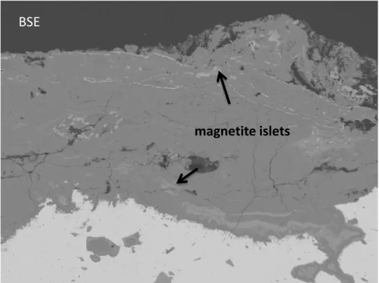
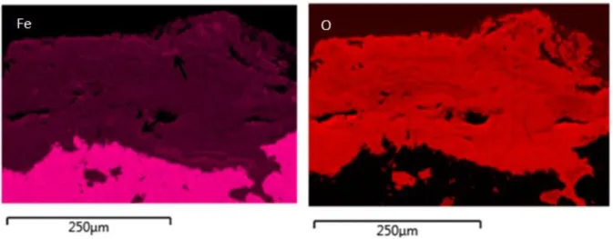
An example of the corrosion pattern where the magnetite islets are in the CPL is given in
Figure 5. This figure displays a BSE image and SEM EDS maps of Fe and O in the CPL.
BSE
15
Figure 5 - BSE image and SEM EDS maps of Fe and O in the CPL.
In the BSE image, magnetite islets are clearly noted (see arrows on the image). They
appear brighter than the carbonate matrix because of their higher mean atomic number.
These magnetite islets are also evident on the Fe map by Fe enrichment (see arrows on the
map).
Each of these corrosion patterns was investigated separately in terms of electrical
properties determined by C-AFM experiments.
3.1 Corrosion profiles containing only FeII carbonates:
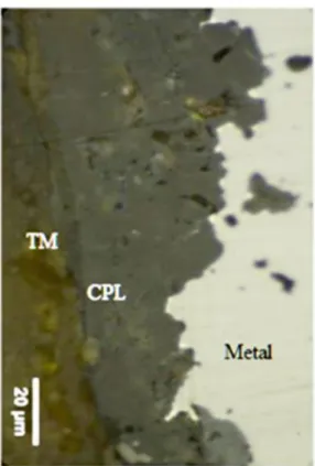
An optical image obtained of the transverse section of the archaeological nail GL07-35
(Figure 6) shows different layers from the metal to the external part. As observed by studies
related to the characterization of the corrosion forms on various archaeological iron
artefacts buried in the carbonated anoxic sites of Nydam Mose and Glinet [3, 5-7], this
transverse section consists of: an iron metallic core where the artefact is not entirely
corroded; a corrosion layer called CPL in contact with the metal that is denser than the burial
environment; a more porous layer that is TM containing soil compounds (quartz, silica,
16
Figure 6 – Archaeological nail GL07-35: optical micrograph of the transverse section.
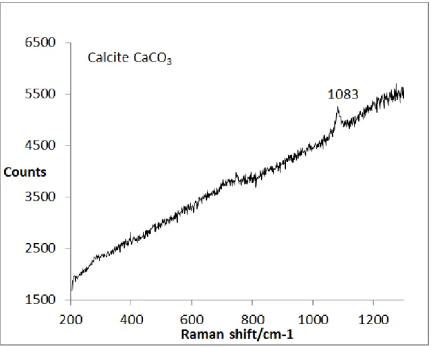
On the µRS maps (Figure 7) corresponding to the optical micrograph of Figure 6, the only
presence of FeII carbonates is highlighted: siderite FeCO3 through its main Raman peak at
1084 cm-1 and chukanovite Fe2(OH)2CO3 with its main Raman peak at 1068 cm-1 [7]. Calcite,
CaCO3, revealed by its very narrow and sharp peak at 1086 cm-1 and its high fluorescence
yield, is present only in the TM. The other Raman peaks of each spectrum correspond to the
17
19
Figure 7 – Archaeological nail GL07-35: µRS maps corresponding to the optical micrograph of Figure 6. Distribution of chukanovite Fe2(OH)2CO3 (a); siderite FeCO3 (b); calcite CaCO3 (c) and
their associated µRaman spectra (d, e, f).
C-AFM investigations in backside contact were performed on the zone (square on the
optical micrograph – Figure 8a). The AFM topography and current images were collected
simultaneously (Figures 8b and 8c) and a good correlation between the surface topography
and the current is evident.
Figure 8d shows the current profile obtained with an imposed voltage of + 500 mV on
the mapped zone on each side of the metal (M)/CPL. The part of the profile located in the
metal presents various current values with a maximum of 2.5 nA. The current measured at
20
In the CPL zone only composed of siderite and chukanovite, the current values are
always lower than the detection limit (50 fA). Indeed at +500mV the CPL is behaving as a
pure insulator. However, the electrical behaviour can change from insulating to conductive
when materials with semi-conductor properties are submitted to a negative or positive
voltage, such as semi-conductors in the Schottky contact configuration. Mativetsky et al. [23]
have shown that under ambient conditions, graphene oxide, which is a semi-conductor,
undergoes a sharp transition from an insulating to a conductive form, reduced graphene
oxide (rGO), when a sufficiently large negative bias is applied between the C-AFM probe and
the counter-electrode. With a sample voltage of -1 V to + 1 V applied to this zone of the CPL,
no current was measured excluding semi-conductor properties for ferrous carbonates, but
21
22
Figure 8 – Archaeological nail GL0735: optical micrograph (a), squared zone and its C-AFM topography image (b), current image (c) and current profile between metal and CPL
(d) (bias = + 500 mV, backside contact).
3.2. Corrosion profiles with magnetite embedded inside the ferrous carbonate matrix
- Magnetite strips at the CPL/TM interface:
Figure 9a displays an optical image representing a zone where the corrosion product
layer is composed of siderite FeCO3 as indicated by Raman spectra obtained at this location
23
(main peak at 1080 cm-1 - Figure 9b). A brighter strip is observed in the CPL. The µRaman spectrum obtained from this strip corresponds to magnetite Fe3O4, which is well
characterized by its main Raman signal at 671 cm-1 (Figure 9c). Between the magnetite strip and the metal, In the outer zone of the magnetite strip, the presence of calcite CaCO3
revealed by the Raman spectrum and its very narrow carbonate peak at 1086 cm-1 signals the TM (Figure 9d). Therefore, the magnetite strip is located at the CPL/TM interface, as is
often the case for iron archaeological artefacts corroded long-term in carbonated anoxic
26
Figure 9 – Archaeological nail GL12-72: optical micrograph (a) and µRaman spectra corresponding to the different zones in the CPL and in the TM (b, c, d).
Siderite FeCO3 (1), magnetite Fe3O4 (2) and calcite CaCO3 (3).
A surface of 40 µm X 40 µm across the magnetite strip was mapped by C-AFM. An initial
experiment was performed with backside contact geometry. A topography image (Figure
10a) was simultaneously collected with the current image (Figure 10b). First, it is interesting
to note the high correlation between the surface morphology and the electrical
measurement. Secondly, the current image indicates a maximal value of 4.5 nA for
magnetite, contrary to the rest of the CPL that did not show any measurable current. In
addition, a smaller surface, 5.2 µm X 5.2 µm, of the magnetite strip was mapped in
topography (Figure 11a) and in current (Figure 11b). The current image clearly shows that
27
These measurements confirmed the insulating character of both the CPL and the TM.
Concerning magnetite, the out-of-plane geometry (see Figure 2) does not confirm that this
28
Figure 10 – Archaeological nail GL12-72: C-AFM topography image (a) current image (b) of 40 µm X 40 µm across the magnetite strip and current profile (c)
29
Figure 11 – Archaeological nail GL12-72: C-AFM topography image (a) and current image (b) of the magnetite strip evident on the previous C-AFM image (bias = + 500 mV, backside
contact).
To determine the electron conduction channels inside the CPL by measuring the in-plane
current, C-AFM in front side contact geometry was conducted to map the same zone. In this
configuration, the C-AFM images (Figures 12a and 12b) show that the magnetite strip
presents a heterogeneous and significant current, suggesting the existence of a lateral bulk
conduction channel. As in this mapped zone, the magnetite strip is not directly connected to
the metal on the observable surface (see the optical micrograph Figure 9a). These
measurements could suggest the connectivity of magnetite strips to the metal in the bulk of
30
Figure 12 – Archaeological nail GL12-72: C-AFM topography image (a) and current image (b) of 10 µm X 10 µm across the magnetite strip
31
- Magnetite islets in the CPL carbonate matrix:
A third corrosion profile observed in the archaeological artefacts from Glinet
corresponds to magnetite islets, completely embedded in the CPL and made of FeII carbonates. Figure 13a displays the optical micrograph of this type of corrosion profile,
archaeological nail GL 12-72 at X50 magnification. As for the previous profile, magnetite
strips can be observed at the CPL/TM interface as well as in the form of nodules of
several microns embedded in the CPL matrix. This CPL matrix is made of siderite as
shown by the Raman spectra collected at this location (Figure 13b). Spectra collected of
the islets show a less intense signal with a broad band at ~ 660 cm-1 corresponding to a poorly crystallized magnetite (Figure 13c). The peak of siderite at 1080 cm-1 is also evident on this spectrum.
C-AFM topography and current images were obtained for the transverse section in a
zone of the CPL containing such magnetite islets (Figure 14), marked ‘2’ on the optical
micrograph in Figure 13a. The C-AFM topography image is heterogeneous and shows
significant differences between the carbonate matrix and the magnetite. The magnetite
topography is homogenous and its nodule can be precisely located. It is characterized by
higher current values. This shows that the magnetite nodules are connected to the
metallic substrate, even if they are trapped in an insulating siderite matrix. It is
interesting to note that for the same voltage, the current values in the magnetite strips
are lower than those measured in the magnetite nodules (some tens of pA and hundreds
32 +
1
2
+Metal
CPL
a)
33
Figure 13 – Archaeological nail GL1272: optical image at X50 (a) and µRaman spectra (b and c). Siderite FeCO3 (b) and poorly crystallized magnetite Fe3O4 (c).
34
Figure 14 – Archaeological nail GL12-72: C-AFM topography image (a) and current image (b) across the magnetite nodule. The corresponding nodule is the point 2 on the Figure 10a
(bias = + 500 mV, front side contact).
3.3. Corrosion profiles containing iron sulfides.
In addition to the presence of the main ferrous carbonate compounds (siderite and
chukanovite) and magnetite, iron sulfide islets can be also present in the CPL of the
archaeological nails as shown on the optical micrographs, at two magnifications, of the CPL
(Figure 15). These phases are present at the TM/CPL interface or mixed in the ferrous
carbonate matrix. Their crystalline nature was determined by µRaman and a diversity of iron
sulfides was revealed. Spectrum 1 indicated a mix of mainly crystalline mackinawite FeS1-x
(main peak at 301 cm-1) as well as some greigite Fe3S4 (main peak at 357 cm-1). Spectrum 2
also corresponds to a mix of greigite and crystalline mackinawite. This diversity of iron
sulfides supports the findings of previous studies on the same type of artefacts [9, 24]. The
presence of the ferrous carbonate matrix of the CPL is also indicated by the presence of the
35
Figure 15 – Archaeological nail GL12-72: optical micrographs of the CPL at two magnifications with the presence of iron sulfide islets and µRaman spectra for the determination of their crystalline nature (1: mix of crystalline mackinawite FeS1-x/greigite
Fe3S4 with mainly mackinawite; 2: mix of crystalline mackinawite FeS1-x and greigite Fe3S4).
The optical micrograph, the C-AFM images and the current profile curve obtained
from the front side contact geometry are presented in Figures 16a, 16b, 16c and 16d
respectively. The current image (Figure 16c) exactly follows the iron sulfide shape
36
observed on the optical micrographs of the CPL displayed in Figure 16a. From the current
profile curve, the maximal current value of this iron sulfide can reach 4pA.
From the current profile curve, the magnetite strip situated near the sulfide zone also
shows similar significant current values up to 2pA. Between the iron sulfide islet and the
magnetite strip, the carbonate matrix of the CPL is clearly shown to be isolating. The fact
that significant current values were measured in the iron sulfides suggests that these
phases are conductive and connected to the metal, despite being embedded in an
isolating FeII carbonate matrix. The similarity of the current values for magnetite and iron sulfides (Figures 16c and 16d) indicate that these phases have similar electrical
resistivity which corresponds to the data reported in the literature for these
semi-conductors: between 10-3 and 5x10⁻³ .cm for iron sulfides and between 10-3 and 10-2 .cm for magnetite [25-27].
37
38
Figure 16 – Archaeological nail GL12-72: Optical image with iron sulfides and magnetite strip (a), C-AFM topography image (b), current image (c) and current profile curve (d) for
a diversity of phases present in the CPL (ferrous carbonates, magnetite strips, iron sulfides) in the CPL (bias = + 500 mV, front side contact).
4. Discussion
Table 1 reports the corrosion patterns obtained from the corrosion systems observed on
39
Table 1 – Summary of the corrosion patterns obtained by µRaman of the different iron nails with their electronic properties established by C-AFM.
Description of the corrosion pattern
observed on cross section
Electronic properties of the CPL
Ferrous carbonates only: siderite FeCO3
and chukanovite Fe2(OH)2CO3
Insulating
Presence of magnetite as strips at the
CPL/TM interface without visible
connection to the metal on the cross
section
Ferrous carbonates: insulating
Strips: conductive (up to 100nA)
Presence of magnetite as islets isolated in
the ferrous carbonate matrix
Ferrous carbonates: insulating
Magnetite: less conductive (~10pA) than
magnetite strips (~100nA) at the same
conditions as C-AFM experiment.
Presence of iron sulfides in the external
part of the CPL composed of ferrous
carbonate without visible connection to
the metal on the cross section
Ferrous carbonates: insulating
Iron sulfides: conductive (~4pA)
Magnetite strip (visible on the same C-AFM
current image): (~2pA)
The corrosion products typical of a deaerated corrosion in a carbonated environment
have been highlighted: the CPL is mainly composed of ferrous carbonate phases such as
siderite and chukanovite, as previously reported in various studies concerning archaeological
artefacts [3-9] or low-carbon steel coupons corroded for a few months in laboratory
40
formed through the aqueous anodic dissolution of iron metal with the carbonate anions of
the medium [14, 28].
In a few zones of the CPL, minor phases are observed, such as magnetite present in the
form of strips at the CPL/TM interface or as islets surrounded by the ferrous carbonate
matrix. The presence of magnetite in the periphery of the CPL and in the outer part of the
ferrous carbonate matrix could correspond to the first step in the corrosion process of the
iron objet [29]. However, magnetite was not only evident in the outer part of the CPL but
was also observed in the carbonate matrix, as in the studies by Saheb et al. [30]. In this latter
configuration, the formation of magnetite could result from local changes in temperature,
pH and carbonate concentration. As indicated by the Pourbaix diagram that shows the
existence of magnetite and ferrous carbonate domains, depending on changes in local
conditions, ferrous carbonates or magnetite can be present in the CPL.
Iron sulfides are also observed in the CPL suggesting a possible role of
sulfate-reducing bacteria, while the growth metabolism is based on the transformation of the
sulfate anions of an anoxic medium into sulfide ions. The subsequent formation of iron
sulfides is due to the interaction of ferrous ions from the anodic dissolution of iron metal
and sulfide ions [9, 31]. The magnetite strips and islets, as well as iron sulfides present in the
ferrous carbonate matrix or at the CPL/TM interface do not present visible connectivity to
the iron metal in the cross section.
From the C-AFM measurements, the corrosion patterns containing only ferrous
carbonate phases, such as siderite and chukanovite, are non-conductive on a
sub-micrometric scale and according to the minimal current detectable by C-AFM which is 50fA.
This is consistent with the fact that this phase is reported to be isolating [20]. Some studies
41
demonstrate less resistive behaviour due to the local presence in the measured zone of
undissolved components from the steel, namely cementite Fe3C [32]. In the present study,
these compounds that are reportedly micrometric in size [20] were not observed by either
optical microscopy or µRaman.
The resistivity values reported for magnetite in the literature are 10-2-10-3.cm [25, 27] due to closeness of Fe2+ and Fe3+ on octahedral sites. In our study, regardless of morphology (underneath strips or islets) inside the CPL, the C-AFM measurements reveal an electrical
connection with the metallic substrate even far from the M/CPL interface in the outer part
of the insulating CPL made of carbonates.
Moreover, weaker electrical conduction is observed for the magnetite islets with the
measured current in the tens of pA, compared to hundreds of pA for the magnetite in strips.
This difference in conductivity values could be due to a lower crystallinity of the magnetite
islets. Indeed, Sarkar et al. [33], by coupling XRD, TEM and impedance analysis, studied the
effect of variable sized magnetite nano-hollow spheres (from 100 to 725 nm in diameter) on
electrical properties and observed that larger spheres are more conductive than smaller
ones. Lopez Maldonaldo et al. [34] examined the effect of crystallite size on the conductivity
of magnetite nanoparticles of sizes (30, 40 and 50 nm) by coupling TEM and EIS
observations: these authors showed that the resistivity of magnetite increases with a
decrease in crystallite size.
Concerning iron sulfides, the resistivity values are reported to be between 10-3 and 5x10⁻³ .cm [27] suggesting electrical conductivity in these compounds. In our study, the iron sulfides demonstrated conductive behaviour. Although they are embedded in the
insulating ferrous carbonate matrix these results show that iron sulfides are connected to
42
The fact that magnetite and iron sulfides are connected to the metal, despite being
located in the outer part of the insulating ferrous carbonate matrix or embedded inside it,
raises the question of how this connectivity happens. C-AFM measurements provide
two-dimensional information and the possible presence of a network made of magnetite and/or
iron sulfides in the volume of the CPL, and electrically connected to iron metal, could explain
these observations.
These findings have important consequences for the corrosion mechanisms of such
systems. The electrons produced by the anodic dissolution of metallic iron could be
conducted to different locations in the CPL (islets of magnetite, sulfur-containing phases or
strips of magnetite) leading to a decoupling of anodic and cathodic corrosion reactions. Our
observations complete those obtained by Saheb et al. [6, 7] with a reaction tracing based on
the use of the Cu2+/Cu0 redox couple on the thick ferrous corrosion layer of iron archaeological nails corroded in anoxic carbonated environments. These authors revealed
the presence of Cu0 nodules in the whole CPL suggesting that the electrons are consumed everywhere in the layer. Here we see that, on the one hand, the cathodic reaction could
happen anywhere in the layer where magnetite or sulfur is present and connected to the
metal, even at distances up to 100 µm from the metal/CPL interface. On the other hand, the
fact that carbonates are not conductive contradicts the possibility of reducing Cu2+ anywhere in the layer as suggested in [6,7].
Another important consequence of this study is that the transport in the corrosion layer
(and especially that of the oxidative species such as H2O in the pores of the corrosion
products) may not be the only mechanism controlling the kinetics. The number of connected
43
5. Conclusion
This study illustrates the value of combining characterization methods such as µRS, and
FEG-SEM and C-AFM to describe, at the sub-micrometric and nanometric scales, the
corrosion product layers of iron corroded in carbonated anoxic environments. µRS was
conducted to determine the crystalline nature of the corrosion products and FESEM to
document their distribution. The electrical properties of the corrosion product layers were
characterized by C-AFM. The main phase identified in the CPL is composed of ferrous
carbonates (siderite, or a mixture of siderite and chukanovite) and is insulating. The
conductive character of the CPL is induced by the presence of magnetite or iron sulfides
located at the TM/CPL interface or inside the CPL and connected to the metal. This may
suggest that the electrons produced by the anodic dissolution of iron metal could be
conducted to the external part of the CPL through a nanometric tridimensional network of
magnetite strips locally connected to the metal and passing through the ferrous carbonate
matrix.
The data concerning the electronic properties of the CPL will be expanded by X-ray
tomography experiments to obtain information at the nanometric scale on the porosity
network inside the CPL and to identify the distribution of magnetite and iron sulfides in the
entire volume of the CPL.
Acknowledgements
The authors wish to thank Dr Cindy Rountree for her helpful and fruitful discussions
44
References
[1] A. Demoz, S. Papavinasam, K. Michaelian, R.W. Revie, Measurement of corrosion potentials of the internal surface of operating high-pressure oil and gas pipelines, Journal of ASTM International 5 (2008) 300-312.
[2] A. Clanfield, F. Cattant, D. Crusset, D. Féron, Corrosion issues in nuclear industry today, Materials Today 11 (2008) 32-37.
[3] D. Neff, P. Dillmann, L. Bellot-Gurlet, G. Beranger, Corrosion of iron archaeological artefacts in soil: characterisation of the corrosion system, Corrosion Science 47 (2005) 515– 535.
[4] M. Saheb, D. Neff, P. Dillmann, H. Matthiesen, E. Foy, Long-term corrosion behaviour of low-carbon steel in anoxic environment: characterisation of archaeological artefacts, J. Nucl. Mater. 379 (2008) 118–123.
[5] M. Saheb, D. Neff, P. Dillmann, H. Matthiesen, E. Foy and L. Bellot-Gurlet, Multisecular corrosion behaviour of low carbon steel in anoxic soils: Characterisation of corrosion system on archaeological artefacts, Materials and Corrosion 60, No. 2 (2009) 99.
[6] M. Saheb, D. Neff, L. Bellot-Gurlet and P. Dillmann, Raman study of a deuterated iron hydroxycarbonate to assess long-term corrosion mechanisms in anoxic soils, J. Raman Spectrosc. 42 (2011a) 1100-1108.
[7] M. Saheb, D. Neff, C. Bataillon, E. Foy, P. Dillmann, Copper tracing to determine the micrometric electronic properties of a thick ferrous corrosion layer formed in anoxic medium, Corrosion Science 53 (2011b) 2201-2207.
[8] Y. Léon, M. Saheb, E. Drouet, D. Neff, E. Foy, E. Leroy, J.J. Dynes, P. Dillmann, Interfacial layer on archaeological mild steel corroded in carbonated anoxic environments studied with coupled micro and nano probes, Corrosion Science 88 (2014) 23-35.
[9] S. Grousset, M. Bayle, A. Dauzeres, D. Crusset, V. Deydier, Y. Linard, P. Dillmann, F. Mercier-Bion, D. Neff, Study of iron sulphides in long-term iron corrosion processes: characterisations of archaeological artefacts, Corrosion Science 112 (2016) 264-275.
[10] Y. Léon, P. Dillmann, D. Neff, M. Schlegel, E. Foy, J.J. Dynes, Interfacial layers at a nanometre scale on iron corroded in carbonated anoxic environments, RSC Advances 7 (2017) 20101.
45
[11] C. Bataillon, C. Musy, M. Roy, Corrosion des surconteneurs de déchets, cas d’un surconteneur en acier faiblement allié, J. Phys. IV France (2001) 94-99.
[12] M. Schlegel, C. Bataillon, F. Brucker, C. Blanc, D. Prêt, E. Foy, M. Chorro, Corrosion of metal iron in contact with anoxic clay at 90°C: characterization of the corrosion products after two years of interaction, Applied Geochemistry 51 (2014) 1-14.
[13] B. Soerensen, D. Gregory, In-situ preservation of artefacts in Nydam-Mose, Metal 98 Conference on Metals Conservation, Draguignan-Figanières, France, 1998, ed. W. Mourey, L. Robbiola, James & James, London, 94-99.
[14] H. Matthiesen, L.R. Hilbert, D.J. Gregory, The occurrence and stability of siderite as a corrosion product on archaeological iron from a waterlogged environment, Stud. Conserv. 48 (2003) 183–194.
[15] N. Taniguchi M. Kawasaki, S. Kawakami, M. Kubota, Corrosion behaviour of carbon steel in contact with bentonite under anaerobic condition, in: Prediction of long term corrosion behaviour in nuclear waste systems, in: Proceedings 2nd International Workshop, European Federation of Corrosion and ANDRA, Nice, 2004.
[16] V. Fell, M. Ward, Iron sulphides: corrosion products on artifacts from waterlogged deposits, in: Metal 98 Conference on Metals Conservation, Draguignan-Figanières, France, 1998, ed. W. Mourey, L. Robbiola, James & James, London.
[17] D. Arribet-Deroin, Fondre le fer en gueuses au XVIe siècle. Le haut fourneau de Glinet en pays de Bray (Normandie) in Archéologie, Paris I Sorbonne, Paris, 2001.
[18] N. Platts, D. Blackwood, C.C. Naish, Anaerobic oxidation of carbon steel in granitic groundwaters: a review of relevant literature, in: SKB (Ed.), Technical Report, SKB, Stockolm, Sweden, 1994.
[19] N.R. Smart, D.J. Blackwood, L. Werme, Anaerobic corrosion of carbon steel and cast iron in artificial groundwaters: Part 1 – Electrochemical aspects, Corros. NACE Inter. 58 (2002) 547-559.
[20] J.L. Crolet, N. Thevenot, S. Nesic, Role of conductive corrosion products in the protectiveness of corrosion layers, Corros. NACE inter. 54 (1998) 194–203.
[21] R.M. Cornell, U. Schwertmann, The Iron Oxides: Structure, Properties, Reactions, Occurrences and Uses, Wiley-VCH Verlag, Weinheim, 2003.
[22] N.N. Greenwood, Ionic Crystals Lattice Defects and Nonstoechiometry, Butterworths, London, 1968.
46
[23] J.M. Mativetsky, Y.L. Loo, P. Samorı, Elucidating the nanoscale origins of organic electronic function by conductive atomic force microscopy, Journal of Materials Chemistry C, 2 (2014) 3118-3128.
[24] J.A. Bourdoiseau, M. Jeannin, C. Rémazeilles, R. Sabot and P. Refait, The transformation of mackinawite into greigite studied by Raman spectroscopy, Journal of Raman Spectroscopy, 42 (2011) 496-504.
[25] N.M. Botrous El Radramany, E.F. Mina, H.D. Merchant, S. Arafa, Electrical Resistivity of magnetite and nickel ferrous ferrite above 300°K, Journal of the American Ceramic Society, 62 No. 3-4 (1979) 113-116.
[26] I.C. Pearce, R.A.D. Pattrick, D.J. Vaughan, Electrical and magnetic properties of sulfides, Reviews in Mineralogy and Geochemistry, 61 (2006) 127-180.
[27] L. Blaney, Magnetite (Fe3O4): Properties, Synthesis, and Applications, Lehigh Review, 15 (2007).
[28] C. Rémazeilles, P. Refait, Fe(II) hydroxycarbonate Fe2(OH)2CO3 (chukanovite) as iron
corrosion product: Synthesis and study by Fourier Transform Infrared Spectroscopy, Polyhedron 28 Issue 4 (2009) 749-756.
[29] R. Bertholon, La limite de la surface d’origine des objets métalliques archéologiques, Caractérisation, localisation et approche des mécanismes de conservation, in Archéologie Paris I, Paris, 2000.
[30] M. Saheb, M. Descostes, D. Neff, H. Matthiesen, A. Michelin, P. Dillmann, Iron corrosion in anoxic soil: comparison between thermodynamic modelling and ferrous archaeological artefacts characterised along with the local in situ geochemical conditions, Applied Geochemistry 25 (2010) 1937-1948.
[31] C. Rémazeilles, M. Saheb, D. Neff, E. Guilminot, K. Tran, J.A. Bourdoiseau, R. Sabot, M. Jeannin, H. Matthiesen, P. Dillmann, P. Refait, Microbiologically influenced corrosion of archeological artefacts: characterisation of iron(II) sulfides by Raman spectroscopy, Journal of Raman Spectroscopy 41 (2010) 1425.
[32] G. Schmitt, M. Mueller, M. Papenfuss, Understanding localized CO2 corrosion of carbon steel from physical properties of iron carbonate scales, Corros. 99 NACE Inter., Houston, (1999) Paper 38.
[33] D. Sarkar, M. Mandal, K. Mandal, Domain controlled magnetic and electric properties of variable sized magnetite nano-hollow spheres, Journal of Applied Physics 112 (2012) 064318.
47
[34] K.L. Lopez Maldonado, P. de la Presa, M.A. de la Rubia, P. Crespo, J. de Frutos, A. Hernando, J.A. Matutes Aquino, J.T. Elizalde Galindo, Effects of grain boundary width and crystallite size on conductivity and magnetic properties of magnetite nanoparticles, J. Nanopart. Res., 16 (2014) 2482.