HAL Id: cea-02509685
https://hal-cea.archives-ouvertes.fr/cea-02509685
Submitted on 17 Mar 2020HAL is a multi-disciplinary open access archive for the deposit and dissemination of sci-entific research documents, whether they are pub-lished or not. The documents may come from teaching and research institutions in France or abroad, or from public or private research centers.
L’archive ouverte pluridisciplinaire HAL, est destinée au dépôt et à la diffusion de documents scientifiques de niveau recherche, publiés ou non, émanant des établissements d’enseignement et de recherche français ou étrangers, des laboratoires publics ou privés.
Chlorine management in thermal processes.
Florent Lemont, Sébastien Francois
To cite this version:
Florent Lemont, Sébastien Francois. Chlorine management in thermal processes.. IT3- 34th Inter-national Conference on Thermal Treatment Technology, Oct 2015, Houston, United States. �cea-02509685�
Chlorine management in thermal processes. Florent LEMONT, Sébastien FRANCOIS
CEA, DEN, DTCD, SCDV, LPIC, F-30207 Bagnols-sur-Cèze, France
Abstract
Thermal processes are increasingly used to treat industrial or municipal organic waste. For instance cogeneration that is able to use one part of the internal energy waste is becoming more popular. Incineration is often used for the treatment of industrial waste. Incineration vitrification is under development for organic nuclear waste processing. Whatever the case, the presence of chlorine in the waste leads to severe corrosion problems in the process.
To mitigate these difficulties in an incineration process for radioactive waste contaminated by plutonium (IRIS), the CEA has investigated the processes by which potentially hazardous compounds are produced in order to eliminate them or prevent their formation. The studies have led to propose a phosphate-based stabilization technique thanks to an addition of phosphorus in the waste. Through a reaction occurring in gas phase, the metals are stabilized under a phosphate form when the formation of volatiles chlorides is avoided. This very efficient technique has been applied for the nuclear waste incineration and has substantially improved process maintenance and security. It could be used for other application in the field of nuclear, household, industrial… waste processing.
Keywords: Thermal treatment, Incineration, Heavy metals, Chlorides, phosphatation, dechlorination
1. Introduction - The IRIS Process and the Elimination of Chlorides
To treat organic waste contaminated by α-emitting actinides from glove boxes in the nuclear industry, the CEA has developed an incineration process named after its pilot facility, IRIS (Installation for Research on Incineration of Solids). Figure 1 is a general overview of the process.
Figure 1. Schematic representation of the IRIS process
IRIS is a three-step process implemented in rotating kilns [1]. The first step consists in oxidative pyrolysis at 550°C, producing pitch that is then processed in a calcining step at 900°C in oxygen-enriched atmosphere. The off-gases arising from the thermal treatments include a volatile hydrocarbon fraction that is oxidized at 1100°C in an afterburner. A multistep process has two advantages. The elimination of chlorine at low temperature in the pyrolyzer limits corrosion problems and allows operation with low gas flow, which also limits particle entrainment. Adding oxygen during the pyrolysis step oxidizes the heavy hydrocarbons that
the calciner being a rotary kiln heated at 900°C. The pitch remains around 2 hours in this furnace and is transformed into a ash having a very low carbon content (< 1%). On leaving the afterburner, the gases are carried to a very high-efficiency treatment system with filter stages to trap the solid particles transported and thus all the α-emitting actinides. Before discharge to atmosphere, the gas stream is submitted to caustic scrubbing to eliminate the volatile acids.
The material balance in the process is about as follow: a feeding rate of 4kg/h produces around 1550g/h of pitch, 111 g/h of ashes and 47g/h of dust.
Although this technology limits corrosion, it does not completely prevent the production of metal chlorides. However, both thermochemical analysis and experimental findings show that the presence of oxygen in process systems favors the formation of silicates or aluminates rather than chlorides. Only volatile zinc chloride is formed in significant quantities, resulting in a very high chlorine concentration in the particulates. In general, the presence of element likely to react with chlorine to form volatile chloride will have a similar effect. This is the case for zinc, but also for lead, cadmium, etc. The particle matter appears to contain more than 95 wt% zinc chloride, which is very detrimental to the process facilities because this extremely hygroscopic product becomes deliquescent when exposed to ambient air. In this form it has a corrosive action that leads operators to maintain the facilities at high temperature even when they are not in use. One means of avoiding this difficulty is to convert the chlorides into more stable compounds. In earlier work [2] chloride ions were successfully replaced by phosphate ions, yielding much more stable and nonvolatile phosphate compounds. This was done by introducing a compound such as tributyl phosphate (TBP) in the pyrolyzer or by using the phosphorus contained in a waste component.
Although this technique is effective, it modifies the physicochemical nature of the compounds transported in the process, resulting in the appearance of localized deposits that may have negative effects on process control. Eliminating them or limiting their occurrence is a major issue today, and will require a better understanding of the mechanisms involved in their formation.
The present paper exposes in its different parts and through experimental and theoretical approaches, the main results obtained regarding the understanding of the behavior of several mineral embedded in hazardous waste and gives some proposals to upgrade the running of thermal processes. If the studies have been performed on the specific case of the IRIS process, the results may be very helpful for all other kind of thermal processes involving plasma torches or other heating means.
2. Behavior of Mineral Loads in a Thermal Process such as IRIS
2.1 Moderate-Temperature Pyrolysis Step
- Experimental and calculated results
The studies were carried out on an average composition representative of glove box waste from a Mixed OXide fuel (MOX) production facility. The waste composition is indicated in Table I.
Table I. Representative average waste composition
Component wt% PVC-1 19 PVC-2 12 Latex 17 Neoprene 17 EVA 25 Cotton 5 Kleenex® 5 Total 100
The difference between PVC-1 and PVC-2 lies in the much higher phosphorus content of the former. This material can be used for the phosphate treatment described above, although other liquid or solid compounds can of course also be used. Table II shows the results of a detailed elemental analysis of the waste composition:
Table II. Waste elemental composition
Element C H Cl O Al Zn Si S N P Ca K Ba Na Sb
wt% 60.61 8.41 16.36 9.55 0.66 0.54 0.48 0.43 0.40 0.23 0.19 0.14 0.04 0.04 0.03
The behavior of the elements within the process was initially assessed through thermodynamic equilibrium calculations based on minimizing the free enthalpy of the system, using FactSage® V.5.4.1 software to simulate the equilibria. With a database of about 4500 identified compounds, it determines the minimum chemical potential considering that the material balance must be conserved and the quantity of each species must be non-negative. The parameters taken into account are those indicated in Figure 1, and the operating pressures are assumed equal to 1 atm.
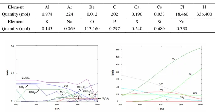
Material input is based on the initial system composition for 4 kg of waste per hour, and cerium oxide CeO2 was added to simulate plutonium behavior. Table III shows the molar composition of the simulation mixture. Figure 2 indicates the nature of the compounds likely to form during pyrolysis, and allows their formation to be estimated as a function of the temperature.
Table III. Initial system composition
Element Al Ar Ba C Ca Ce Cl H
Quantity (mol) 0.978 224 0.012 202 0.190 0.033 18.460 336.400
Element K Na O P S Si Zn
Quantity (mol) 0.143 0.069 113.160 0.297 0.540 0.680 0.330
Figure 2. Equilibrium system composition versus temperature (Left: solids; Right: gases)
This type of simulation shows that if the system is allowed to remain at equilibrium, a complex mixture of silicates, phosphates and chlorides would form. The equilibrium is not reached because of low kinetics but also because of interactions between compounds. Thus, it is interesting to compare these calculated results (Table IV) with analyses of the char from the first step of the process.
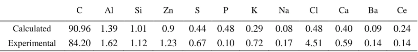
Table IV. Equilibrium calculations (550°C) versus process analysis results for char from the IRIS process (wt%)
C Al Si Zn S P K Na Cl Ca Ba Ce
Calculated 90.96 1.39 1.01 0.9 0.44 0.48 0.29 0.08 0.48 0.40 0.09 0.24
Experimental 84.20 1.62 1.12 1.23 0.67 0.10 0.72 0.17 4.51 0.59 0.14 0.14
For most of the elements the simulations and analysis results are relatively consistent except for chlorine, for which the actual concentration was much higher than the equilibrium value. It is assumed that this difference is mainly due to the fact that chlorine is a heteroelement found in polymers (like sulfur) having relatively complex degradation mechanisms. Studies are now in progress to understand several phenomena that can lead to equipment malfunctions. The initial results confirm that some polymers such as neoprene or PVC subjected to a temperature increase may have complex degradation behavior. In the case of neoprene, for example, thermogravimetric analysis [3] showed such complexity, with polymer degradation beginning at temperatures between 500 and 600°C depending on the heating rate. The delay, which is related to the presence of sulfur stabilizing the polyisoprene structure, shows that the pyrolysis temperatures and residence times of the IRIS process may be insufficient.
- Interaction between gases and pitch – the case of ZnCl2
The main issue of this work is to find one way to avoid the formation of zinc chloride in the thermal process and thus to understand the mechanism leading to its formation and release. The table IV shows that a large amount of chlorine is driven toward the calcinatory when it was suppose to go directly to the afterburner. If one part of it may remain in unpyrolysed plastic, one other can be adsorbed on the surface of the pitch produced in the pyrolysor.”
Indeed, in addition to these degradation processes, it is important to consider the conditions in which certain gaseous species are generated in the pyrolysis step. The surface of the pitch being formed may be activated to some extent. The volatilization of some species such as chlorides [4] will therefore be influenced by their adsorption on the solid and their accumulation in its pores. In this case, mass transfer to the surrounding environment of a gaseous species partially adsorbed in a carbonaceous solid must be considered. This approach must allow for such mechanisms, described in a particle of radius r by the following expression:
2 2 2 p p e q C C C D t t r r r ∂ ∂ ∂ ∂ ρ + ε = + ∂ ∂ ∂ ∂ (1)
where ρp is the bulk density of the solid, q the concentration of gaseous species adsorbed, εp the particle
porosity, De the diffusivity, C the concentration of the gaseous species in the pores, and r the particle center
radius.
If the adsorbing solid/mineral vapor system is assumed to reach equilibrium, this expression can be simplified by introducing a pseudo-diffusion coefficient D*:
2 * 2 2 C C C D t r r r ∂ = ∂ + ∂ ∂ ∂ ∂
(
)
* / e p p D D q C = ε + ρ ∂ ∂ (2)The pseudo-diffusion coefficient D* can be assumed constant (isothermal equilibrium) and q = KC, where K is the adsorption constant.
Allowing for radiative transfers at each particle [4], for which the expression is similar to eq (2), the change in the quantity of inorganic vapor in the solid is given by the following expression:
( )
2 2 2 * 2 2 0 1 6 1 n RD t n q t e q n π ∞ − = = π∑
(3)q;¯(t) is the mean metal concentration in each particle, and is defined as follows:
2 3 0 3 R q qr dr R =
∫
(4)In this approach, D* must be determined from the diffusivity coefficient De calculated from the diffusion
coefficient D as follows: p e p D = ε D τ (5)
εp is the material porosity and τp its tortuosity. Specific studies of the structure of char particles [5] gives
values of 0.55 and 1.41, respectively.
D is calculated by comparing the mean free path l of a gas molecule (in this case ZnCl2) and the mean pore radius δ; l is calculated from following expression:
2 2 = π φ RT l PN (6)
where P is the total pressure (1 atm) and φ the mean diameter of the molecule. As ZnCl2 is linear and ionic, φ is about 0.87 nm. Hence l can be estimated at about 33 nm.
BET porosimetry measurements give a mean pore radius of 15 nm (corroborated by Eghlimi et al. [5]). Thus l and δ are of comparable magnitude, allowing D to be calculated from the following expression:
1 1 1
K m
D = D +D (7)
DK (the Knudsen diffusivity) is calculated using the following equation:
1 8 3 K RT D M = δ π (8)
As M is the molar mass of zinc chloride (136.29 g·mol-1), D
K = 1.79 × 10⁻⁶ m2·s-1
The molecular diffusion coefficient of zinc chloride at 550°C is not known but may be approximated from the data for mercury chloride [4] using the following expression:
2 2 2 2 2 2 850 600 HgCl HgCl HgCl 550 600 ZnCl HgCl ZnCl 5 D D M D D M ° ° ° = ° − − (9)
This calculation gives 5502 ZnCl
D ° = 7.7 × 10⁻⁵ m2·s-1; D can thus be calculated from expression (7), giving D = 1.75 × 10⁻⁶ m2·s-1 and D
e = 6.8 × 10⁻⁷ m2·s-1
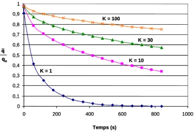
The adsorption constant K in this expression is unknown. However, the evolution of the q;¯/qo ratio as a function of this constant can be observed. The results of this approach are indicated in Figure 3.
0 0,1 0,2 0,3 0,4 0,5 0,6 0,7 0,8 0,9 1 0 200 400 600 800 1000 q qo Temps (s) K = 1 K = 10 K = 30 K = 100 0 0,1 0,2 0,3 0,4 0,5 0,6 0,7 0,8 0,9 1 0 200 400 600 800 1000 q qo q qo Temps (s) K = 1 K = 10 K = 30 K = 100
Figure 3. q;¯/qo ratio as a function of time and of the adsorption constant K
It appears that the volatilization of zinc chloride, which can be expressed by 1 − q;¯/qo, is strongly dependent on the value of K. For example, the values for silica, clay and alumina are respectively about 6, 24 and 37; the value for the IRIS char (activated charcoal) is thus presumably situated at a higher level. However, Figure 3 shows that for a value of 30 and a processing time of 5 minutes (300 s, the average pyrolyzer residence time), ZnCl2 volatilization does not exceed 30% of the initial content. Even if the processing time is significantly extended, it is obvious that 50% will be difficult to achieve. This type of behavior has already been observed in other applications [6], and incites us to reconsider the routing of volatile metallic species in the process via the calciner before reaching the afterburner.
Both the experimental and computational results concerning the pitch composition indicated in Table IV show that zinc tends to remain in the solid. Indeed, for a feeding rate of 4kg/h of waste and thus 22g/h of zinc, the flow rate of zinc going with the pitch is 19g/h when its flow rate in the gases is 3g/h. Figure 2, showing a state of equilibrium, indicates that it would be in the form of ZnS. The data in Table IV indicate rather a chloride form. Comparing this result with studies of the degradation kinetics of neoprene or latex containing all the sulfur [3] shows that zinc remains largely adsorbed in the pores of the char as ZnCl2. Additional analysis consisting to leach the pitch 48 hours with pure water shows that 97 wt% of zinc is soluble. Contrary to zinc chloride ZnCl2, the zinc sulfide ZnS is not soluble in water attesting that the zinc is well under the chloride form.
2.2 High-Temperature Calcining Step
The residence time for the calcining step is about 2 hours, allowing the system to approach thermodynamic equilibrium. An operation similar the one carried out for pyrolysis was performed using the results obtained during the first simulation, with two corrections:
• Aluminum in the form of AlPO4 was introduced as Al2O3 to approximate the experimental concentrations in Table IV.
Table V indicates the quantities of solids entering the calciner according to the results obtained previously. (Gases required for the treatment such as O2 and Ar have been taken into consideration for the calculation and then appear in the table.)
Table V. Elements supplied to the calciner
Compound Quantity (mole)
C 143.74 Al2SiO5 0.359 ZnCl2 0.262 Al2O3 0.092 SiO2 0.167 Al2Si2O6 0.075 NaCl 0.069 Ca5P3O13H 0.038 K2CeCl5 0.033 BaCl2 0.012 O2 89.286 Ar 178.57
The system evolution according to the temperature is shown in Figure 4.
Figure 4. Equilibrium system composition versus temperature (Left: solids; Right: gases)
The solid species formed show a relatively stable system completely devoid of carbon, with a possible emergence of liquids that could disrupt system operation. These liquids can be pure (e.g. BaCl2) or specific compounds not listed above. Concerning the gases, ZnCl2 is completely vaporized, and other gaseous species such as KCl or NaCl appear. The comparison with experimental results shows very strong ZnCl2 volatilization from the calciner, which can condense in the ducts resulting in serious maintenance problems. Table VI compares the results of equilibrium calculations with the experimental results.
Table VI. Equilibrium calculations versus process analysis results for ashes from the IRIS process (wt%)
Table VI shows that the ash quality obtained generally corresponds to the results of a simple equilibrium calculation. The most significant differences concern volatilized zinc and sodium, and can be explained through an approach similar to the previous one, as well as through zinc speciation different from ZnCl2 and not present in the database. For example, X-ray diffraction analysis of the ashes not only confirmed the presence of aluminosilicates, but also revealed traces of ZnS and phosphates. The quantity of mineral collected during an incineration campaign was about 110 g·h-1, compared with the computational speciation results of 116 g·h-1, which is very satisfactory for an industrial application.
Today the theoretical and experimental results regarding the evolution of the mineral load during the first two stages of the incineration process are relatively satisfactory, and allow us to understand the mechanisms controlling the gas composition and the phenomena observed in and downstream from the afterburner.
3. Optimizing the Phosphate Treatment
3.1 Conventional phosphatation
As indicated in the process description, the introduction of phosphorus should allow conversion of the volatile chlorides into phosphates. It can be added either as organic liquid such as Tri Butyl Phosphate (largely used in nuclear industry as actinides extractant) directly into the pyrolysor [2] or under other liquid form (Ammonium Hydrogeno Phosphate, Tri Aryl Phosphate, …). Whatever the chosen way, previous studies [2] have shown that the addition of phosphorus to the incinerable waste stream in stoichiometric proportions with zinc (XP/XZn ≥ 0.7 ) results in virtually complete conversion of zinc chloride to zinc phosphate. This conversion
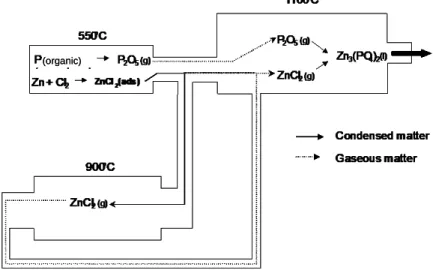
effectively occurs, since the particles collected on the filters consist mainly of zinc phosphate but it is only partial, because zinc chloride condenses between the pyrolyzer and the calciner, as this species is captured by the char. Analysis have been performed on sampling of deposits collected at different points of the process. They have permitted, together with the previous results, to propose a mechanism of phosphatation and thus to propose a flow diagram for the species involved in the phosphatation reaction (Figure 5).
Figure 5. Phosphorus and zinc flows in the IRIS process
C Al Si Zn S P K Na Cl Ca Ba Ce
Calculated 0 21.93 16.46 0 0 2.32 0.50 0 0.65 6.56 1.39 3.98
Experimental 0.35 17.00 12.40 0.58 0.15 1.08 2.86 0.87 0.41 7.59 0.98 2.67
(organic) (organic)
Other volatile species may be involved in this process, of course. The analyses showed that potassium and sodium are present in the particles, which is consistent with the gas compositions indicated in
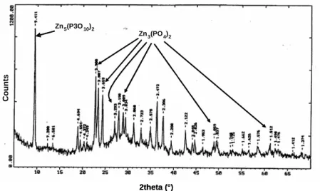
Figure 5. In agreement with the theoretical analysis and the experimental results, phosphatation of the volatile reactive species occurs in the afterburner and produces a compound assumed to be zinc orthophosphate Zn3(PO4)2. Speciation studies have shown that while this species is indeed found in the particles, other polyphosphates such as Zn2P2O7 or Zn5(P3O10)2 are also present. The X-ray diffraction diagram of the particulates in Figure 6 reveals peaks associated with orthophosphate together with other peaks associated with various phosphates. This characterization was carried out on a Brüker AXS D8 Advance diffractometer (λCu = 1.5406 Å). The diffractogram were compared to the ICDD base data.
Figure 6. X-ray diffraction diagram of electrostatic precipitator dust sample
These mixtures — whose composition depends directly on the reactive conditions in the afterburner (temperature, pressure, Zn/P ratio, etc.) and on the cooling conditions — can lead to systems having characteristics incompatible with optimum process operation. For example studies on systems limited to the pseudo-binary ZnO-P2O5 [7] were used to define a phase diagram with several identified compounds (Figure 7) and high anhydride concentrations resulting in low melting points.
Figure 7. ZnO–P2O5 phase diagram [7]
The phase diagram shows that whatever the compound(s) formed in the afterburner, the system will have fluxing properties and will thus easily form deposits. Since the phosphating reaction occurs in the gas phase, it produces a mist of phosphate microdroplets in suspension in the off-gas stream. They can impact the furnace well and remain liquid, or impact and solidify on the afterburner outlet duct. Observations in the facility showed major deposits [8] in the furnace outlet that were too crystallized to be analyzed by X-ray diffraction. However, elemental analysis confirmed that they were zinc phosphates.
Zn3(PO4)2 Zn5(P3O10)2 Zn3(PO4)2 Zn5(P3O10)2 2theta (°) C ount s Zn3(PO4)2 Zn5(P3O10)2 Zn3(PO4)2 Zn5(P3O10)2 2theta (°) C ount s
3.2 Addition of phosphorus in the calciner
The work just described on the incineration behavior of the waste mineral load was the basis for proposing and implementing technological developments destined to improve the overall process. The prior studies showed that zinc chloride, resulting from the combination of chlorine from PVC and zinc from neoprene, is adsorbed and enters the calciner where it is volatilized and transferred to the afterburner (Figure 5). The phosphating reaction occurs in the afterburner to produce zinc phosphate, whose composition can vary depending on the quantity of phosphorus in the system (Figure 7). While the phosphate treatment substantially diminishes or even eliminates zinc chloride, it produces compounds that may be liquid and thus form deposits that can disrupt fluid flow. Studies were undertaken to assess the feasibility of performing phosphatation directly in the calciner, in which the residence times and temperatures can be sufficient to ensure chemical conversion. The thermodynamic approach cannot be limited to the formation of zinc orthophosphate Zn3(PO4)2, as no data are available concerning pyrophosphates Zn2P2O7 or Zn(PO3)2 or
polyphosphates. The study can be limited to investigating the evolution of the following systems:
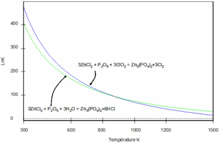
3ZnCl2(g) + P2O5(g) + 3/2O2(g) = Zn3(PO4)2 + 3Cl2(g)
3ZnCl2(g) + P2O5(g) + 3H2O(g) = Zn3(PO4)2 + 6HCl(g)
In both cases, an advanced degree of reaction progress is reached and the equilibria can be considered complete. When the equilibrium constants are plotted versus the temperature (Figure 8) in order to illustrate the reaction progress, a lower temperature can be seen to favor the thermodynamics of the reactions.
Figure 8. Phosphatation reaction progress versus temperature
As in the case of pyrolysis, the chemical systems involved in calcination are relatively complex; phosphate cross reactions and interactions between elements should be taken into account. Work recently initiated in this area will take into account the multiple interactions and physicochemical behavior of the mineral species produced.
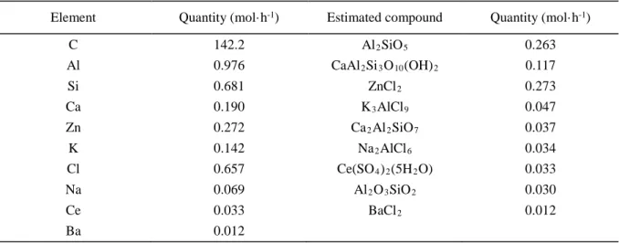
In the event that phosphatation is carried out in the calciner, the pitch composition supplied to the furnace would be modified to eliminate phosphorus in the feed stream. The recalculated composition pitch would then be the following:
Element Quantity (mol·h-1) Estimated compound Quantity (mol·h-1) C 142.2 Al2SiO5 0.263 Al 0.976 CaAl2Si3O10(OH)2 0.117 Si 0.681 ZnCl2 0.273 Ca 0.190 K3AlCl9 0.047 Zn 0.272 Ca2Al2SiO7 0.037 K 0.142 Na2AlCl6 0.034 Cl 0.657 Ce(SO4)2(5H2O) 0.033 Na 0.069 Al2O3SiO2 0.030 Ce 0.033 BaCl2 0.012 Ba 0.012
The degree of phosphatation will of course depend on the phosphorus content, but also on the quantity of oxygen introduced, which will determine the oxidizing properties of the calciner environment. In the case of an oxygen deficit, the reducing conditions characterized by a high CO content will limit phosphatation by constraining phosphorus to P2O3 and/or P4O6. Excess oxygen relative to carbon will create a sufficiently oxidizing environment to ensure phosphatation of zinc as Zn3(PO4)2 or in a form richer in phosphorus such as Zn2P2O7. Based on orthophosphate, the only form present in the databases, the evolution of zinc-based compounds was calculated and is shown in Figure 9 (to ensure that Zn3(PO4)2 is included, the calculations were performed with the Thermodata database- Coach Bank 00 V06-00). In this case an optimum operating point appears, corresponding to a feed rate of 1.6 mol per hour of phosphorus (calculated for a waste feed rate of 4 kg·h-1) and about 300 mol of oxygen, i.e. an oxygen flow rate of about 3.4 Nm3·h-1.
0 0.05 0.1 0.15 0.2 0.25 0.3 0 0.5 1 1.5 2 ZnSiO4 Zn3(PO4)2 ZnAl2O4 ZnCl2 O = 4.5 m3.h-1 n phosphore(mol.h-1) ZnSiO4 Zn3(PO4)2 ZnAl2O4 ZnCl2 3 -1 Q ua nt it é d e m at iè re ( m ol -1) phosphore -1) 0 0.05 0.1 0.15 0.2 0.25 0.3 200 250 300 350 ZnCl2 Zn3(PO4)2 Q ua nt it é d e m at iè re ( m ol .h -1) oxygène(mol.h-1) P = 1.6mol.h-1 0 0.05 0.1 0.15 0.2 0.25 0.3 ZnCl2 Zn3(PO4)2 ZnCl2 Zn3(PO4)2 oxygène(mol.h-1) -1 n 0 0.05 0.1 0.15 0.2 0.25 0.3 0 0.5 1 1.5 2 ZnSiO4 Zn3(PO4)2 ZnAl2O4 ZnCl2 O = 4.5 m3.h-1 n phosphore(mol.h-1) ZnSiO4 Zn3(PO4)2 ZnAl2O4 ZnCl2 3 -1 Q ua nt it é d e m at iè re ( m ol -1) phosphore -1) 0 0.05 0.1 0.15 0.2 0.25 0.3 200 250 300 350 ZnCl2 Zn3(PO4)2 Q ua nt it é d e m at iè re ( m ol .h -1) oxygène(mol.h-1) P = 1.6mol.h-1 0 0.05 0.1 0.15 0.2 0.25 0.3 ZnCl2 Zn3(PO4)2 ZnCl2 Zn3(PO4)2 oxygène(mol.h-1) -1 n
Figure 9. Zinc speciation at 800°C versus phosphorus and oxygen concentrations in the calciner
The conversion of zinc chloride to phosphate is optimized for the process if the reaction medium contains sufficient hydrogen to produce hydrogen chloride instead of chlorine Cl2. Adding phosphorus in the form of an organic compound such as TBP (C12H27PO4) ensures this conversion. The studies carried out showed that the quantity of hydrogen supplied by this compound is sufficient to diminish the chlorine concentration to very low levels and ensure optimum conversion of chlorine to HCl, which is then neutralized in the scrubbing columns.
While the studies undertaken with respect to phosphatation in the calciner involve chemistry, they must also be accompanied by technological changes in the entire process because a large quantity of fine particles will be released from the furnace. To prevent them from reaching the afterburner where they would be melted, it is therefore necessary to implement a suitable retention system such as a cyclone separator or electrostatic precipitator. The additional cost imposed by this implementation will be offset by the possible reduction of the size of the filtering equipments (a large part of the dust will be recovered together with the ashes) and also thanks to the protection of the equipment guarantee by the elimination of the chlorinated compounds. The initial tests have shown effective phosphate treatment in the furnace tube with significant recovery of
appearance of mixtures melted in the furnace. A theoretical analysis of the ashes obtained for incineration optimized as described above indicates the production of a complex mixture with the approximate composition provided in Table VIII.
Table VIII. Ash composition in the furnace
Compound Concentration (mol·h-1)
AlPO4 0.98 SiO2 0.66 Ca2P2O7 0.095 Zn3P2O8 0.09 CeO2 0.03 Na4P2O7 0.017 BaSi2O5 0.012
Later experiments, carried out with the same wastes, have been followed by analysis performed on ashes, dusts and deposits. The deposits, exclusively present in the very first zone of the rotary kiln was an almost melted mixture, easy to recover.
The table IX provides the theoretical composition of the ashes (from table VIII) and the experimental compositions of ashes, deposits and dusts.
Table IX. Theoretical and experimental composition for ashes, deposits and dusts
Element Ashes Theoretical Composition Wt% Ashes Experimental Composition Wt% Dusts Experimental Composition Wt% Deposits Experimental Composition Wt% Al 11.5 7.5 6.8 3 P 18.6 17.5 9.8 20 Si 8.3 8.8 12.3 8.8 Ca 3.3 4.1 9.3 3.3 Zn 7.6 11.6 11.4 22 Ce 1.8 2.1 1.8 2 Na 0.7 0.9 3.2 2.2 Ba 0.7 0.3 0.4 0.4 Cl 0 0.8 1 1.2 O 47.5 - - -
The oxygen composition has not been analyzed explaining why it does not appear in the table. The table shows a rather good agreement between the calculation and the analysis for the ashes except for the chlorine that can react with other element than Zn before released in the gas stream.
Even if the speciation of each element has not been performed, it was interesting to compare the ratios between (nAl+nCa+1.5nZn+nNa ) and nP to be consistent with table VIII. The results show a ratio of 0.7 for the deposits, 0.9 for ashes and 2.7 for the dusts that contain no more than 1wt% of chlorine (0.7 mol%) testifying
a good efficiency of the reaction. It is interesting to note that the sodium and zinc contents in the deposits is much more higher than in the ashes. This may explained why the deposits are almost a melted mixture. Indeed, mixture of phosphates and oxides (including silica) can lead to the formation of compounds with low melting points that tend to sinter easily. Prior work on the production of phosphate-based composites [9] demonstrated the formation of defined compounds in which alkali metals tended to lower the melting points appreciably. For example, the presence of sodium in our application could result in the formation of a mixed Na2ZnP2O7 compound with a melting point of about 780°C, as shown on the phase diagram in Figure 10.
Figure 10. Liquidus curves for Zn2P2O7 – Na2ZnP2O7 system. 1: Diagram proposed by Fellner et al. [9-10],
2: experimental data points obtained DSC [9], 3-4-5: Diagram obtained by different models [9]
The composition data show that the system obtained in the calciner is probably located in areas richer in sodium, accounting for the possibility of obtaining low melting points leading to the formation of retentions.
4. Conclusion
The management of metals is a major issue in a thermal process for waste treatment, and they must be stabilized as far as possible. This issue becomes crucial when the metals form volatile compounds by combining with elements such as chlorine.
For the treatment of radioactive organic waste, experience has shown that the combined presence of zinc and chlorine generates zinc chloride, whose volatility results in the formation of very corrosive deposits in the off-gas treatment system. An excellent way to overcome this problem is to convert the off-gaseous chlorides into phosphates, much more stable and noncorrosive compounds. In this context, a protocol was developed to carry out this conversion in the IRIS process in two steps, first at moderate temperature and then at high temperature.
The mechanism initially contemplated was volatilization of the phosphorus and zinc in the first step, with recombination in the afterburner heated to 1100°C. Experimentation showed that the volatile element transfer mechanisms are not so simple, and must allow for the adsorption properties of the char in the heart of the process. These properties radically modify the pathways of the compounds, as well as their formation and deposit zones. It is therefore of fundamental importance to study and assess these properties to optimize the processes and help stabilize the corrosive or hazardous compounds.
The application of this study to zinc present in radioactive organic waste incinerated by the IRIS process demonstrated that zinc chloride does not volatilize in the initial pyrolysis step but rather during subsequent calcining where phosphorus is not present to ensure phosphatation. A modification of the procedure for phosphatation of the volatile chlorides was therefore proposed to shift the reaction to the optimum location. When carried out in the zinc chloride desorption zone — i.e. in the calciner — it is highly effective and protects the entire treatment facility.
References
[1] Jouan A., Moncouyoux J.P., Boen R., Cartier R., Vincent J.J., Longuet T., Incineration Processes for Radioactive Waste with High Alpha Contamination: New Developments. IT3 Conference, p 209, 1995 May 8-12th, Bellevue Washington, USA.
[2] Rouault H., Cartier R., Boen R., Longuet T., Phosphorus: In Situ Treatment for ZnCl2, formed by Incineration of Organic Waste. IT3 Conference, p 225, 1998 May 11-15th
[3] Caballero J.A., Conesa J.A., Martin-Gullon I., Font R., Kinetic study of the pyrolysis of neoprene, Journal of Analytical and Applied Pyrolysis, 74 (2005), 231-237
[4] Abanades S., Flamant G., Gauthier D., Modelling of heavy metal vaporisation from a mineral matrix, Journal Hazardous Materials, B88 (2001) 75-94
[5] Eghlimi A., Lu L., Sahajwalla V., Harris D., Computational modelling of char combustion based on the structure of char particles, Second international conference on CFD in the minerals and process industries CSIRO, Melbourne, Australia, 1999, December 6-8.
[6] Marani D., Braguglia C.M., Mininni G., Maccioni F., Behavior of Cd, Cr, Mn, Ni, Pb and Zn in sewage sludge incineration by fluidised bed furnace, Waste management, 23 (2003) 117-124
[7] Shornikov S.I., Shilov A.L., Shults M.M., A Mass-Spectrometric Study of the Thermodynamic Properties of ZnO-P2O5 System Melts, Russian Journal of Physical Chemistry, Vol. 70, N° 3, 1996, pp. 447-453.
[8] Poinso JY, Thiebaut C., Lemort F., Charvillat JP., The alpha waste incinerator at the CEA Valduc. Assessment and improvement of the active waste incineration. IT3 Conference, 2003 May 12-16th, Orlando USA
[9] Ushakov V.M., Borisova N.V., Shultz M.M., A Study of Thermodynamic Characteristics of the Zn2P2O7 – M4P2O7 (M=Li and Na) Systems by Differential Scanning Calorimetry, Glass Physics and Chemistry, Vol. 27, N°3, 2001, pp. 259-266
[10] Felnner P., Majling J., Calculation of Liquidus Curves in Phase Diagrams Na4P2O7 – Mg2P2O7 and Na4P2O7 – Zn2P2O7, Chem. Zwesti, 1973, Vol 27, n°6, pp 728-731