Accuracy analysis of the thrust force in 2D-3D finite element models
G. Deliége(*), F. Henrotte(**) and K. Hameyer(**)(*): TWR, Katholieke Universiteit Leuven, 200A Celestijnenlaan, B-3001Heverlee, Belgium e-mail: [email protected]
(**): RWTH
AbstractThis paper presents the theoretical analysis of the transverse flux linear actuator used for fast and accurate positioning of the lens of a CD-rom player. The purpose is to compute the thrust force as a function of the mover position for different values of the design parameters. A series of models (2D and 3D) corresponding to different levels of approximation of the original problem are considered. A particular attention has been paid to the control of the accuracy of the results by using dual formulations. In particular, the relevance and the accuracy of 2D computations, compared to 3D computations, are discussed in detail.
I. INTRODUCTION
The finite element (FE) method is a versatile and powerful numerical method for the solution of partial differential equations. It is widely used for the numerical analysis of of electrical devices, among others. In general, the design of a solvable finite element model requires several simplifications of the original physical system in order to reduce its complexity. The choice of the approximations may have a rigorous basis, such as a dimensional analysis of the equations. In some cases however, the loss of accuracy resulting from the different approximations is extremely difficult to evaluate and the designer can only rely on his own experience to decide which simplifications are admissible.
This article proposes an analysis of the accuracy of the force computed with different finite element models of a linear actuator. The goal is to determine a finite element model minimizing the computation time but nevertheless yielding sufficiently accurate results, which could be used to perform an optimization of the motor.
After a brief description of the actuator, a 2D and a 3D geometrical models are presented. The dual a and h-phi formulations in 2D and 3D are recalled and a reliable error estimator based on the results of both formulations is defined. The issue of boundary conditions is discussed. Two force computation methods are proposed: a classical method based on the differentiation of energy or coenergy, and a method called "eggshell method" based on the Maxwell stress tensor (MST).
II. DESCRIPTION OF THE MOTOR
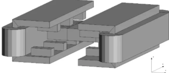
The actuator has been described in detail in previous papers []. It consists of two motors facing each other [1]. The stators are long C-cores with a coil wound around the vertical arm. The lower and upper arms are toothed in such a way that one stator is shifted by a quarter of a pole pitch with respect to the other. Each mover is made of 3 blocks of permanent magnet material magnetised in the direction of motion and separated by blocks of iron (Fig. 1). The movers of the two motors are connected by a block of nonmagnetic material in order to avoid any magnetic
interaction. The actuated optical system is fixed to that central block. As they are magnetically independent, only one motor is modelled.
Fig. 1. Geometry of one half of the linear actuator.
III. FINITE ELEMENT ANALYSIS
The aim of the finite element analysis was the optimization of the force acting on the mover. Under certain conditions, a magnetic equivalent circuit can describe the flux distribution in a permanent magnet machine and determine the force with reasonable accuracy at a low computation cost [Honds]. In transverse flux machines, the intricate geometry renders such an approach troublesome [Laith]. The finite element is in that case the best alternative: it is very flexible regarding the approximation of geometries and the accuracy of the results is controlled by user-defined parameters, such as the number of elements in the mesh.
Geometrical models
The basis model of the actuator consists of one half of the whole machine enclosed in an airbox inside which the magnetic flux is assumed to be confined. In reality, the main part of the flux is likely to remain inside the regions of high permeability, i.e. the iron parts of the stator and rotor, meaning that the surrounding airbox needs only to be large enough to allow leakage fluxes to be modelled. As a matter of fact, an infinite air domain would not necessarily be a better representation of the environment of the machine which is supposed to work inside a CD-ROM device. As the accuracy of the computed force depends mainly on the accuracy of the computed magnetic field in the airgap around the mover, the vertical core and the coil outside the model can be advantageously left outside the model (Fig.).
Figure .
The airgap-centred 3D model focuses on the airgap field and devotes a maximum of the available unknowns to the description of the field around the mover (Fig.). The finite element model is connected to a simple magnetic circuit that accounts for the vertical core and the coil, in order to get in total a complete rigorous model of the system.
Figure .
The three-dimensional effects occurring around the mover cannot be considered by a two-dimensional model. However, the 2D approximation has unquestionable advantages when compared to an entire 3D approach: the definition of the geometry and the control of the mesh quality are much easier and faster and the computation time is significantly lower. Therefore, the design of a 2D model is generally a preliminary step allowing the designer to perform many computations to determine the overall behaviour of the system and to investigate the influence of the parameters, at a reduced computation cost. The 2D model is a slice of the motor in the $X-Y$ plane (Fig.). Two regions are added, above and under the stator teeth, to represent the part of the stator around which the coil is wound.
Finite element formulations
The dual vector potential and scalar potential formulations, which will be referred to as b- and h-formulation respectively, have been used simultaneously. These forumlations provide respectively an upper bound and a lower bound for the magnetic energy [rika]. Therefore, one can define a reliable global error estimator based on the results obtained with both formulations.
h-formulation
The magnetic field is decomposed into the sum of a source field
h
s and the gradient of a magnetic scalar potential
,s
h h
.Since the coil is removed from the geometrical model, the source current density
j
s is zero in the whole domain ands
h
is zero as well, thanks to the fact that the domain is contractible [boss]. Due to the presence of permanent magnet materials, the constitutive law is
c
b
h h
,with
h
c the remanent magnetic field, which is zerooutside the permanent magnet regions.The FE formulation reads:
Find
�
H
( )
such that0 b c
h
b n
� �
�
� �
�
�
�
�
, 0H
,with the function spaces
1 2
( )
(grad, ) :
0,
h hH
�
H
I
,
1 2
0( )
(grad, ) :
h h0
H
�
H
�
. b-formulationFind
a H
�
a( )
such that
1 0 h ca
a
a h
a h
n
Ѵ�Ѵ Ѵ� ��
ᄁ
ᄁ
ᄁ
�
�
�
,
1 0 h ca
a
a h
a h
n
ᄁ
ᄁ
Ѵ�Ѵ Ѵ�
ᄁ
�
�
0 aa
ᄁ
H
ᄁ
,with the function spaces
1
( )
(curl, ) :
0,
b h aH
H
a
a t
� Ѵ �
ᄁ
,
1 2
0( )
(grad, ) :
h h0
H
�
H
�
.IV. DISCRETISATION ERROR
The error analysis by means of dual formulations shows that the error on force converges with the same rate as the error on the energy and coenergy, but is one order of magnitude higher (Fig. 6). We have observed in 2D that a grid of about 25 000 nodes is a good trade-off between accuracy and computation time. The error on the maximum thrust force stands in that case about 3%.
V. 2D APPROXIMATION VI. CONCLUSIONS
[1] G. Deliége, F. Henrotte, H. Vande Sande, K. Hameyer, “3D h-phi finite element formulation for the computation of a linear transverse flux actuator”, International Journal for Computation and Mathematics in Electrical and Electronic Engineering (Compel), vol. 22(4), pp. 1077-1088, 2003. [2] J. Rikabi, C.F. Bryant, E.M. Freeman, “Error-based derivation
of complementary formulations for the eddy current problem”, IEE Proceedings, vol. 135(4), pp. 208-216, 1988.
[3] F. Henrotte, K. Hameyer, “An algorithm to construct the discrete cohomology basis functions required for magnetic scalar potential formulations without cuts”, IEEE Transactions on Magnetics, 39(3):1167-1170, May 2003.