CONTROL ALGORITHMS FOR ADAPTIVE
AND SEMI-ACTIVE SYSTEMS
by
JESSE L. BEAVER
Bachelor of Science, Civil and Environmental Engineering University of Washington, 1999
Associate in Arts, General Studies University of Maryland, 1996
Submitted to the Department of Civil and Environmental Engineering in Partial Fulfillment of the Requirements for the Degree of
MASTER OF SCIENCE
In Civil And Environmental Engineering at the
MASSACHUSETTS INSTITUTE OF TECHNOLOGY
September 2000
@ 2000 Massachusetts Institute of Technology. All rights reserved.
Author:
Depairment of Civil and Environmental Engineering July 28, 2000 Certified by: Jerome J. Connor Professor Thesis Supervisor
700
Accepted by:K"
Daniele Veneziano Chairman, Departmental Committee on Graduate StudiesMASSACHUjSETTS INSTITUTE
SNG
OF TECHNOLOGYCONTROL ALGORITHMS FOR ADAPTIVE
AND SEMI-ACTIVE SYSTEMS
by
JESSE L. BEAVER
Submitted to the Department of Civil and Environmental Engineering on August 4, 2000, in partial fulfillment of the
requirements for the degree of Master of Science in Civil and Environmental Engineering
Abstract
A recent advance in the discipline of Structural Engineering is in the field of smart or intelligent structures. This broad field is attracting much attention as structures exceed historic limitations on span and height. Structures are now required to have service deflections much smaller than previously thought possible to satisfy their unique function. To comply with these increasingly stringent design parameters, engineers have developed structural motion control systems, which are based on passive, active, or adaptive strategies.
This thesis evaluates the application of both time-invariant active and adaptive control systems to a single degree of freedom (SDOF) structure. The time-invariant active control algorithm relies on the rapid and low-power response capability available from magnetorheological (MR) fluid dampers, which provides semi-active feedback. The adaptive control algorithm realizes successful and realistic implementation by
combining the semi-active damper with an active variable stiffness (AVS) system. Both control algorithms are implemented using a finite difference state predictor to estimate the state of the SDOF. This state estimate is combined with a quadratic performance index, which is minimized, to determine the optimal negative gain from the MR damper
as well as the optimal system stiffness. The results illustrate the improved system performance for a controlled system. The discrete numerical simulation uses earthquake
accelerations as the loading for the system.
Thesis Supervisor: Jerome
J.
ConnorAcknowledgements
First, I would like to thank Professor Jerome
J.
Connor. My understanding of this topic would be greatly diminished without his mentoring. I truly appreciate that his door was open to all of my questions, including those unrelated tocoursework. Our conversations ensure that I enter this profession with my eyes open.
Second, thanks to my family. While often enjoyable, my coursework has also been extremely challenging. The words of encouragement from my mother,
Mac, and Maureen were invaluable to me during the tougher times.
Last, I have to thank my class and office mates. Although they often served to distract me from working as diligently as possible, I believe this to be a good thing. At the end of the day, my learning has been greatly increased by our association. It has been a joy to be surrounded by such an interesting and talented group of people.
I INTRODUCTION7 2 COTO SYSTEMS 2.1 2.1.1 2.1.2 2.2 2.2.1 2.2.2 2.3 2.3.1 2.3.2 2.3.3 2.3.4 2.3.5 PASSIVE CONTROL OVERVIEW DESIGN METHODOLOGY ACTIVE CONTROL OVERVIEW DESIGN METHODOLOGY ADAPTIVE CONTROL OVERVIEW FuzzY LOGIC NEURAL NETWORKS RULE-BASED SYSTEMS SEMI-ACTIVE CONTROL 9 9 9 9 13 13 14 17 17 19 20 21 22 3 CONTROL DEVICES 23 3.1 OVERVIEW 23 3.2 PASSIVE DEVICES 23 3.3 ACTIVE DEVICES 24 3.4 ADAPTIVE MATERIALS 26
3.5 SEMI-ACTIVE DEVICES (MR DAMPER) 27
4 CONTROL ALGORITHMS 32
4.1 TIME INVARIANT ACTIVE (SEMI-ACTIVE) CONTROL 32
4.1.1 METHOD 32 4.1.2 STATE PREDICTOR 33 4.1.3 ALGORITHM DEVELOPMENT 34 4.2 ADAPTIVE CONTROL 35 4.2.1 METHOD 35 4.2.2 ALGORITHM DEVELOPMENT 36 5 APPLICATION OF ALGORITHMS 38
TIME INVARIANT ACTIVE (SEMI-ACTIVE) CONTROL OVERVIEW NUMERICAL RESULTS 5.2 ADAPTIVE CONTROL 5.2.1 OVERVIEW 5.2.2 NUMERICAL RESULTS 38 38 39 49 49 49 5.1 5.1.1 5.1.2 ?- CnNTRnLqY TEMS 7
6 SUMMARY AND CONCLUSIONS 61
REFERENCES 64
APPENDIX A 66
A.1 DERIVATION OF STATE-SPACE EQUATION OF MOTION 66 A.2 DERIVATION OF CLASSICAL OPTIMAL FEEDBACK MATRIX 69
A.3 DERIVATION OF DISPLACEMENT PREDICTOR 71
A.4 DERIVATION OF OPTIMAL TIME INVARIANT ACTIVE CONTROL FEEDBACK 73
A.5 DERIVATION OF ADAPTIVE CONTROL ALGORITHM 76
APPENDIX B 79
B.1 TIME INVARIANT ACTIVE (SEMI-ACTIVE) CONTROL SCRIPT B.2 SUMMARY OF GROUND MOTION RECORDS
B.3 EARTHQUAKE RESPONSE GRAPHS FOR TIME INVARIANT CONTROL B.3.1 IMPERIAL VALLEY, EL CENTRO, 270 DEGREES
B.3.2 SAN FERNANDO, POCOIMA DAM 196 DEGREES B.3.3 KERN COUNTY, TAFT LINCOLN TUNNEL, 69 DEGREES B.3.4 KOBE, JAPAN, NS COMPONENT
B.4 ADAPTIVE CONTROL SCRIPT
B.5 EARTHQUAKE RESPONSE GRAPHS FOR ADAPTIVE CONTROL B.5.1 IMPERIAL VALLEY, EL CENTRO, 270 DEGREES
B.5.2 SAN FERNANDO, POCOIMA DAM, 196 DEGREES B.5.3 KERN COUNTY, TAFT LINCOLN TUNNEL, 69 DEGREES B.5.4 KOBE, JAPAN, NS COMPONENT
79 84 85 85 88 91 94 97 101 101 103 105 107
1 Introduction
A structure provides a load carrying system. Structures are designed to meet a goal defined by the user or owner of the structure, with requirements including safety, serviceability, aesthetics, and economics. Structural systems for vertical gravity loads are extremely well established and have been for some considerable time. The loading characteristics are relatively deterministic and, therefore, are straightforward to design for. Additionally, gravity loads often improve, in a manner similar to pre-stress theory, the structural performance of a system subjected to other vertical loads. Conversely, structural systems for lateral loadings are quite varied and not at all standardized. This appears to be the result of the stochastic nature of the loadings as well as the increased complexity and costs of the analysis, design, and standard components.
This thesis is concerned with determining candidate methods for structural design to resist lateral loadings including wind, earthquakes, and other dynamic loads. A promising solution, with many current applications worldwide, is structural control. Structural motion based design or performance-based design, in contrast with traditional design, is based on the serviceability response as well as the strength limitations of the structure. This design methodology meets the requirements by designing a control system to limit specified structural response. Unfortunately, current design relies on an engineer's ability to predict life-cycle loadings to choose the required passive or active control systems. One solution to allow the structure to respond in the optimal manner is to give it some ability to decide on the best course of action. This thought process, in conjunction with recent allied technological advances, leads to the field of intelligent structures and adaptive materials.
In what follows, current control methodology is introduced. To begin, simple examples are presented for passive, active and adaptive control. Next, the mechanical and material devices used to create these control forces are described. With this foundation, the thesis presents two control algorithms. The first is a time invariant active control algorithm with a magnetorheological fluid damper as the recommended actuation device. The terms 'time invariant active control' and 'semi-active control' will be used interchangeably in this thesis, due to the chosen actuator device for that scheme. The second is an adaptive control algorithm that uses a time invariant control scheme in combination with a time variant structural system. The structural modification is accomplished with active variable stiffness devices.
2 Control Systems
2.1 Passive Control2.1.1 Overview
One definition for "passive" as defined by Webster is "not reacting visibly to something that might be expected to produce [a response]...". Thus, a passively controlled structural system is designed to achieve optimal performance with fixed system parameters. This optimal design is determined by prediction of load characteristics such as magnitude and frequency content. The parameters that are varied for design include system stiffness and damping. The operation of this type of structure is illustrated in Figure 2.1.
load
0
system
response
Figure 2.1 Passive control flow diagram 2.1.2 Design methodology
Passive control design for a single degree-of-freedom (SDOF) structure subjected to sinusoidal loading with planar motion will be explained (J.J.Connor, 1996). Figure 2.2 shows the chosen SDOF system configuration.
C
:m .p(t)
k I-*u+ug
|
u
In this system, m represents the constant system mass, c represents the equivalent viscous damping, and k represents the system stiffness. The displacements for the mass and the ground are specified by u and u,, respectively. The applied loading is represented by p(t) = p sin(At), where - is the peak magnitude of the loading and Q is the forcing frequency. The equation of motion for a SDOF is
u+ 2
a
+Wfu = p(t ) (2.1)The solution for u(t) is very well known and may be represented as
u(t) = ez" (Asin(owdt) + Bcos(wOdt)) + k sin(Qt - ) 1-#2+ +(25p)2
(2.2)
where A and B may be determined from the initial system displacement and velocity and
0 = - circular frequency (2.3)
#
= 9 = frequency ratio (2.4)C
=wm - damping ratio (2.5)
Wd = 4 1-2 = damped circular frequency (2.6)
y = tan /_321] -phase angle (2.7)
The solution, equation 2.2, is divided into two parts. The first part is the term multiplied by the exponential, termed the transient solution. The transient
solution rapidly decreases with time for any damping ratio greater than zero. The second term in equation 2.2 is the particular solution, u,(t), which will be the
design focus. For brevity a change in notation will be used.
u,(t = Q, sin(9At - y) (2.8)
a, (t) = -AG , sin(A t - y)= -a, sin(At - y) (2.9)
where Pmis the static displacement response, is the unrestrained response
k m
acceleration and
= - H =max dynamic displacement (2.10)
k
,=
#2H
= max dynamic acceleration (2.11)m 1
H - dynamic magnification factor (2.12)
81-#2 + (2 #)2
Design proceeds by specifying the loading characteristics, i.e. the parameters of p(t), and the system mass estimate, m. In addition, design goals have to be established. For both human sensitivity and structural response, displacement and acceleration are critical measures. Therefore, maximum allowable values of each is specified as u* and a*. The dominant criterion is determined from the relation
a,
= 2 , . If the statement a* < Au* is true, the allowable acceleration isthe critical parameter and 8, is set equal to a'. If that relation is not satisfied, displacement is the critical parameter. The critical measure is then used to determine the allowable dynamic amplification, H*. Entering the figure below with H' will provide 1 or 2 values of the frequency ratio. The choice of damping ratio, if in a damping critical zone (near
p
= 1), will then yield limits on acceptable k values.Figure 2.3 Dynamic amplification design graph
Once these limits are known, economics or other concerns can be used to choose from the acceptable ranges for the system parameters. For example, if
p,
is chosen based on cost, requiringp
<PI,
leads to the limit that k must be greater than km, wherek (2.13)
This methodology is extended to multiple degree-of-freedom (MDOF) systems by using modal response and damping as control goals.
2.2 Active Control 2.2.1 Overview
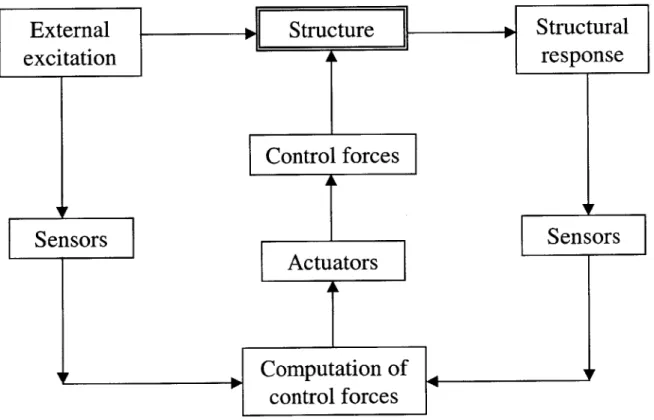
Active control methodologies take a step closer to alleviating some of the risk inherent in a design based on model approximations of system stiffness and damping. The goal of active control is to reduce system response to external loading by the addition of energy. Potential benefits exist for both structural performance and material usage. A schematic of an active system proposed by T.T. Soong in 1990 is shown below. This chart can be described by three activity components: i) identification, ii) decision, iii) action.
Figure 2.4 Active control flow diagram
Identification includes monitoring structural state as well as measuring applied external loadings. The monitored parameters depend on the type of feedback that will be used for control. If structural parameters are the only data used, the
feedback is termed Closed-Loop. If the external loading is monitored, with control based on it alone, the feedback is called Open Loop. A combination of the above can be referred to as Closed-Open Loop control. The sensors shown in Figure 2.4 comprise the identification activity. A wide range of devices from wireless strain guages to mechanical load transducers can perform the sensing.
Decision-making is perhaps the most actively researched part of active control. This stage is where the type (magnitude and duration) of control, that will be applied, is determined. It is typically made up of a digital-processing unit and an algorithm based on some type of structural model. The variety of algorithms in use is extremely varied. The reader is referred to the varied control literature available in both structural publications as well as the electrical and mechanical disciplines. This stage is represented by the "Computation of control forces" block which receives input data from the sensors.
Action taken in active control consists, for example, of a hydraulic actuator applying a force to the structure. These devices or 'actuators' are typically positioned in fixed locations and are used in optimal combinations determined by the control algorithm. The "Actuators" and "Control forces" blocks in the chart above show this stage. Actuator technology will be discussed in Chapter 3.
2.2.2 Design Methodology
To better introduce active control for a dynamic system, the equation of motion for a SDOF will be expressed in a state-space form, with matrices represented by
actual structures, the state-space representation is found to be easier to manipulate and readily extends to a discrete formulation. Ground acceleration can be included in the formulation, and treated similarly to the external forcing function.
X =AX+Bpp+BfF (2.14)
where p p(t) is the arbitrary external forcing function and
0 1 ~0
X =[u]= X(t), A = k c, B, = B, -1 (2.15)
F = F(t)= -Kf X = negative linear feedback (active control force) (2.16)
Kf =[k, k,] =linear feedback/gain matrix (2.17)
Classic time-invariant, linear feedback dictates that A is constant, implying that system stiffness and damping will not vary during loading/reaction, while the structural response remains linear. From the derivation contained in Appendix A, the exact solution at time t for this loading is
X = e^('-'")X(tO )+ eA('r) (BPp(-r) + BfF(r))r (2.18)
If the assumption is made that there is no time delay effects due to the control process, the above equation may be expressed as
X = eAc(t-t X (to)+ feAc (t)B~p(zr)di (2.19)
01
Ac=A-BfKf= k k1 kjj] (2.20)
This shows that the effect of the feedback is to alter system damping and stiffness. A thorough discussion of stability issues and time delay is covered in Introduction to Structural Motion Control,
J.J.
Connor, 2000. A useful conclusion is that time delay can cause instability if the active control uses displacement feedback. Pure, instantaneous velocity feedback cannot cause instability. It is relatively straightforward to visualize and remember this result. If a pendulum swings to the right, reaching its maximum amplitude and begins to swing back to its equilibrium point, velocity feedback will act to slow it down as it is increasing speed. This is desirable negative gain. Conversely if, for the same scenario, displacement feedback is applied, the motion will be reinforced, ineffect causing a positive gain.
The optimal linear feedback is often determined by use of a quadratic performance index,
J.
The components of the performance index are weighting factors, the control forces, and the structural responses to be minimized. An example performance index isJ = 2XQX + F RF dt (2.21)
0
where
Q
and R are diagonal weighting matrices. Appendix A contains the solution corresponding to the above performance index minimization process. The optimal value of Kf. isAT H + HA - HB R-'BH = -Qf (2.23)
2.3 Adaptive Control 2.3.1 Overview
Control methodologies based on adaptive schemes and materials are the ultimate goal of control development. This umbrella classification includes creative use of active control schemes to better optimize resulting structural behavior by use of new materials and learning mechanisms or algorithms. Adaptive control can be thought of as allowing a structural system to change its properties to improve structural performance, often by use of input energy. The adaptive portion of the classification is biologically derived from the characteristic of an organism that
makes it better able to live in its environment (Clark 1998). Thus, it differentiates
itself from active control in that either system properties themselves are changed or a learning mechanism allows differing control response for a similar input loading.
While structures that pop out of a box, self-erect, and self-maintain are envisioned, the present applications are closer to allowing structures to push the current limitations including span, length, rule-of-thumb ratios, and material usage. However, algorithmic development continues and this continuance of development will allow us to achieve truly adaptive structures. The engineering process is followed with small steps, not an overnight solution.
Successful adaptive and time-invariant active control requires a different design approach. Firstly, the decision to design adaptively is chosen before design begins, in the conception stage. This is due to the anticipated alterations, from passive design, for properties such as the member sizes, which are often significantly reduced. Secondly, it is realized that the potential effectiveness of the control system is reduced if it is installed in a structure after the passive design and gravity load bearing members are in place. The approaches to implementation are actively discussed at the relevant structural conferences and symposiums (see Proceedings of World Conferences on Structural Control). To illustrate adaptive control, several methods will be described, including fuzzy logic, neural networks, rule-based and semi-active systems. The following chart
Figure 2.5 Adaptive control flow diagram
This chart differs from the active control chart as follows. Firstly, the optimal action is able to draw on some weighting scheme, which can be set in place or learned by the system throughout its life-cycle. Secondly, the action taken as a result of the optimal action computation can be more varied including alterations to actuator locations or real-time system property changes.
2.3.2 Fuzzy Logic
Fuzzy logic systems provide a set of rules that determine necessary feedback. The 'fuzziness' in this scheme is that the rules are not based on TRUE-FALSE
tests. Instead the rules allow for regions where the criteria may be partially satisfied. Relations between rules and weighting functions are defined. The weighting functions are determined prior to system installation and are kept constant throughout the life of the system. Fuzzy control is an application of
fuzzy set theory (Zadeh 1964).
The advantage of fuzzy control over binary control is that the trade off between priorities more closely resembles the human decision-making process. Additionally, vague input loadings can be more easily classified. This is understood by examining a temperature control device. Binary control would classify the temperature as too hot or too cold. Fuzzy control adds classifications such as warm, cool, humid, etc...
A.W. Nicklisch, 1999, illustrates fuzzy control applied to adaptive prestressing of a concrete beam. In his thesis, fuzzy logic is used to determine the amount of prestress force to apply to the high strength steel tendons, at any time, based on state feedback of the strains in the beam. The benefits of this system are clear when the entire construction process is considered, i.e. unloaded beam to fully loaded beam.
2.3.3 Neural Networks
Artificial neural networks is the area of adaptive research that is envisioned as most promising for the goal of creating smart or intelligent systems. These networks differ tremendously from fuzzy or rule-based systems in that they
receives sensor data. This data is passed to one or more hidden (middle) layers containing transfer functions and weightings. The resulting transformed data is passed to an output layer. The output layer receives information about system state and checks this with the prediction determined by the transfer functions contained in the hidden layers. Corrections are then made to these transfer functions and weights. The system requires a tremendous amount of training as it is experience-based rather than knowledge-based.
Applications are quite varied including but not limited to construction operation and management, damage detection, structural monitoring, structural analysis and soil mechanics. Rafiq et al. explore the application of neural networks to optimize a reinforced concrete beam section in Artificial neural networks aid conceptual design. The neural network is named for the interconnectivity of the nodes and the closeness it bears to a simplified human decision-making scheme.
2.3.4 Rule-Based Systems
Rule-based systems are designed with a set of rules, which determine when and how control will be implemented. These systems are similar to those entitled Knowledge-based or expert systems. The idea is to determine the parameters of the system that are to be controlled. These parameters are then given some type of bounds and are monitored. If these bounds are crossed, a corrective action is prescribed based on some optimization algorithm. The system does not require any training. The boundaries are established for well-known limitations, such as the maximum stresses allowable at a specific location. The rules then specify a corrective action, which attempts to minimize this same quantity.
A typical rule scheme might be to prioritize structure response and control force cost while accounting for control force limitations or saturation. The sensors will be placed at locations that are determined based on the required system information. Feedback from the state and or the loading can determine the course of action. Most of these systems do not improve with experience. Often the rule system is in place at installation and is not able to write new rules for itself. Even in these cases, the algorithm can be replaced with an improved scheme and placed to use the existing actuator framework. The control algorithms suggested in this thesis are rule-based.
2.3.5 Semi-Active Control
Semi-Active control is a combination of active control schemes with adaptive materials. Semi-active devices receive an input of power, as active devices do, but they do not input energy into the structural system. Instead, the power is used to alter some property of the device itself, allowing it to remove energy from the controlled system. The properties altered may be either the physical configuration or the rheologic properties. System energy removal is often accomplished through negative velocity feedback, providing an energy sink. The systems proposed in this thesis use a semi-active feedback device.
3 Control Devices
3.1 OverviewStructural control, in its many forms, relies on a coupling of the structural control algorithm and the control device that carries out the actions deemed optimal. Often, it is this combination that determines the success of the control. The different control methodologies previously described, and their variants, are implemented by a host of mechanisms and actuators. The devices may be loosely classified as passive, active, adaptive and semi-active devices. Although the focus of this chapter will be on a semi-active device solution, the other types will be briefly described.
3.2 Passive Devices
Passive control devices are built in place with no intent to alter configuration or performance throughout their life cycle. This requires a very good idea of what type of control may be required of this system in the future. These components may be divided into stiffness and damping devices.
The stiffness devices provide a response to displacement within the structure, similar to the function of a spring for the typical 'mass on a spring' scenario. Their function is to change the structural response by altering the natural period of the system. Examples of stiffness devices include shear walls, cross-bracing and base-isolation systems.
The damping device is a mechanism to remove energy from a system and to limit the peak dynamic response measures. These devices often perform this action as a function of the system velocity. Dampers include friction, viscous and hysteretic devices to name a few. Friction devices respond to a change in displacement with energy absorption proportional to the amount of displacement. Viscous devices remove energy through cycles of system motion, with a response force proportional to the velocity at any instant. Hysteretic devices are mechanisms that experience plastic deformation with energy absorption through cycles of material deformation. One common geometric configuration is the piston damper, similar to the shocks on a car. All structural systems have some passive damping, even if small, due to the natural friction between system/building elements during dynamic action. This is included in system models as structural damping.
3.3 Active Devices
Active control devices differ significantly from passive devices. Where passive devices seek to remove energy from a system, active devices often seek to add energy that provides a response to an external energy forcing. To visualize, imagine a wind gust forcing a structure to bend leeward. One type of active device could seek to provide a real force, which would oppose this leeward displacement, resulting in no actual structural deformation or displacement, or at least a greatly reduced response. These devices are often called actuators. The most common configuration is that of the linear actuator, shown in Figure 3.1. Hydraulic, electro-mechanical or electro-magnetic forces often drive these systems.
Structure Actuator
Figure 3.1 Linear actuator
The ensemble of active control actuators is immense, including but not limited to active mass drivers, active tuned mass drivers, active tendon systems, active variable stiffness devices, the previously mentioned linear actuators and combinations of these devices. The advantage to this type of response is apparent; the structure may take action to prevent excessive deformation. The limitation is that an accurate estimate of the potential loadings must be known to design the system.
When choosing actuators, the goal is to find a mechanism capable of delivering a large response force in a very small amount of time. It is also preferable to choose a device that will operate from a relatively small power source. Typical devices for civil structures provide feedback forces on the order of a meganewton. This feedback is required, in the case of earthquake loadings, to respond on the order of milliseconds. These criteria will shape the choice of actuator technology used in the control scheme outlined in this thesis.
The active variable stiffness (AVS) devices are categorically classified as active devices, but do not actually add energy to the system. Instead, these devices
change the dynamic response properties of the structure by altering its natural frequency. Kajima Corporation utilized the active variable stiffness system for adaptive control of building structures. Their system uses chevron bracing, which is able to engage or disengage. This state change is accomplished by attaching some type of clutch mechanism or a small hydraulic actuator to the connection joint of the bracing. The device is useful for control because it is operated by an extremely small power source and is rapidly shuttled between its active and inactive state. Inclusion of multiple AVS devices provides a great range of variability of the system stiffness, but it is understood that this variability is only available in discrete steps as the clutch mechanisms are either on or off.
3.4 Adaptive Materials
Adaptive materials have an ability to alter their rheological properties. Examples include piezoelectric actuators, shape memory alloys and controllable fluids. Piezoelectric materials respond to an input current by a combination of expansion-contraction similar to the poisson effect of conventional materials. Shape memory alloys are materials trained to a specific shape before use. They are then reformed into another shape and put in place. An increase in their temperature will cause them to revert to the trained shape. Controllable fluids include electrorheological and magnetorheological materials. These two materials change their yield stress by application of an electrical current and a magnetic field, respectively.
soundproofing of automobiles, by the process of active noise control, Modelling and Control of Adaptive Mechanical Structures. The materials of the roof are designed to disrupt incoming sound waves, by changing their shape, causing destructive interference. Additional early uses are in the aeronautical field for reduction of flutter in structural members and in the robotics field for sensing and causing small motions. Unfortunately, most classical uses of adaptive materials can produce forces only on the order of hundreds of newtons. This has reduced their usefulness for civil structural applications, which require forces on the order of a meganewton.
3.5 Semi-Active Devices (MR Damper)
Although there are several varieties of semi-active systems, the discussion here will center on magnetorheological (MR) fluid and its use in a piston-configured damper. Rheology is the study of deformation and in MR fluids a magnetic field causes a change in the deformation properties of the fluid. MR fluid is the next step in the evolution of semi-active materials, following electrorheological (ER) fluids. Current advances in MR fluid research and development have shown it capable of providing a response force on the order of 20-50 times that available from the ER fluid (RheoneticTM Magnetic Fluids & Systems) with a reduction in both the power required and the response time. In light of this, and the scalability of these systems required for even the smallest civil structures, it is believed that MR fluid will eclipse this market, much diminishing the use of ER
fluid.
This type of device may be envisioned as a shock on a car, similar to the passive equivalent viscous damper. The difference is that this shock can change the fluid
it contains to suit the particular bump that it is currently being subjected to, i.e. it provides more resistance to a larger bump than to a smaller bump. This maximizes the effect of the damping and aids prevention of the rapid acceleration caused by moving the shock to its limit or 'bottoming-out'. An additional benefit is the reduction of susceptibility to instability, often caused by fully active feedback, as previously discussed.
MR fluid is a mixture of a hydrocarbon fluid, such as oil, and iron particles. These particles are encouraged, by adjustment of fluid densities and various admixtures, to remain as thoroughly dispersed throughout the fluid as possible. Although knowledge of magnetorheological fluids is not new, it is the reduction in gravitational settling that has caused renewed interest in their application. The operation is then very simple. Application of a magnetic field across the device containing the fluid encourages the particles to align themselves forming a chain. This alignment causes the viscous fluid to gain a yield strength causing a response similar to the Bingham solid. The process may be visualized as follows.
Magnetic field
00
Passive Bingham Solid
The Bingham model is composed of a Coulomb friction element placed in parallel with a viscous damper. The feedback force, F, that this model provides may be represented by
F =
f,
+f,
+f,
(3.1)In this formulation, fc represents the frictional force and is applied in a direction opposite to the system velocity. The term f, represents the velocity-proportional, viscous damping effect of the fluid with or without a magnetic field applied. This portion of the force is relatively small, when considering dampers scaled for civil structures. It may, therefore, be included in the system damping parameter as a constant and excluded from the control concerns. The last term, f, accounts for the geometry of the physical device. In the case of the damper configuration, it would represent an accumulator, which would create an internal pressure in the damper to prevent fluid cavitation. This leads to a small nonzero quantity for the velocity activated feedback force of the damper on the system, at all times.
System control occurs through adjustment of the frictional force, f, by alteration of the fluid yield stress. Yang et al. describes ramping up of the yield stress in terms of the simple resistor-inductor circuit powered by a current driver, as shown in Figure 3.3.
R
i(t)
L
The model is created to express the amount of time required for the damper to attain a specified yield strength as a function of the current in the coil which is proportional to the voltage applied to the system.
the circuit is
The governing equation for
L i(t)+ R -i(t )+ i(t)= id dt2 dt
where
L coil inductance
R coil resistance
di -desired current
i(t) = circuit current at time = t
The required voltage, V(t), is incorporated in the following feedback loop.
-v(t )= y{id -i(0)
dt
(3.2)
(3.3)
where y is the proportional gain. Adjustment of the gain to achieve an underdamped system
((=
R /(24 yL) <1) results in much faster response times. The first time at which the current attains the desired current is_ 2L (;r - arctanB) (34)
R fl
where
#l=
(4yL)/R2-1. This electromagnetic circuit was evaluated for 2 coil configurations, parallel and series. The shortest response time was obtained for the parallel configuration.Unlike other types of actuation devices, MR devices have the potential to respond in milliseconds. Thus, the limitation for control concerns is the time it takes to shuttle the coil current between two specified values. This is dependent on the available voltage, equation 3.3, and the device configuration. The 20 ton (200 kilonewton) device tested at the University of Notre Dame required approx 0.014s to increase its feedback force by 10 kilonewtons. The time to reduce the force was found to be even less at 0.009s per 10 kilonewtons.
The only major manufacturer of MR devices, currently, is the LORD Corporation of North Carolina. Their most popular mass-marketed device using this technology is a truck seat motion-damping device. LORD Corporation has also produced several prototype dampers for University experimentation (B.F. Spencer et al.).
4 Control Algorithms
4.1 Time Invariant Active (Semi-Active) Control 4.1.1 Method
To approach system control, a goal must be established. This goal may be thought of as the combination of the system parameters to be controlled as well as the desired performance of these parameters due to the control. The goal chosen for this thesis is to minimize both the displacement of the system and the magnitude of the damping force necessary to control the system motion. To enable attainment of this goal, data such as an estimate of the structural response, the input loadings, and the effect of system alterations is desired.
Structural response and input loadings will be supplied by structural monitoring. Sensors will be placed at discrete locations that enable determination of the necessary physical data, such as relative displacement of the structure with respect to the ground and the ground motion. The remainder of the data will be determined by mathematical approximation as part of the semi-active control algorithm. The process will be use a quadratic performance index. To begin, the methodology for determination of structural state will be
4.1.2 State Predictor
Prediction of structural motion can be performed by a variety of routines. One such method is to approximate the equation of motion with a finite difference scheme called the Central Difference Method. The method is termed explicit integration because the information that is sought is future information based on past data. The derivation may be found in Appendix A. The resultant recurrence equation is shown below.
2m c m
_
At2 -k__ _____ u++ tfu
+ 2At At2 U1 + r-}maj + Fj) (4.1) m c Km + m + At 2 2At At 22At At2 2At
where m, c, k are as previously defined and At time step
Uk displacement at time t = tk
F interval damping force
a discrete earthquake acceleration from ground motion record
The Central Difference Method is conditionally stable, if the time step used, At, is less than a critical time step, Atc, = T/n, where T is the natural period of the structure to be controlled. In the case of this thesis, the time step is 0.02 seconds while the natural period of the structure is on the order of 50 times this time step, approximately 1 second. This stability assertion may be verified by any standard Mechanical Vibration/Dynamics reference such as Structural Dynamics: Theory and Applications, Joseph W. Tedesco et al. It is encouraged, for SDOF, to limit the maximum time step to a very small value or approximately 0.01T.
4.1.3 Algorithm Development
Using the conditionally stable displacement predictor presented above, a performance index will be established for determination of optimal semi-active feedback. This index,
J
,,, is a discrete quadratic cost function which is associated with the time interval between t and t,., = I [qju2 1 + rF2] (4.2)
where u,,,,is as previously described and q, weighting of displacement at time = t
r, weighting of damping force for interval under consideration
This cost function will be combined with a constraint equation by use of Lagrange multipliers. This combined equation, termed the Lagrange equation will then be minimized, based on the fundamental premise that a function has some minimum and some maximum over a bounded region. This method seeks to determine the optimal feedback force, F], applied at time, t,. These equations are formulated in Appendix A and shown below.
u =- 2At2u k - 4mu1 + 2muj, - Atcuj_1 - 2At2 (- mag,j) (4.3)
q, 4At4
+ 2m + Atc
r) 2m + Atc
F.
j
u (4.4)Numeric solutions for the above equations are presented in Chapter 5. This thesis will use a semi-active damper to provide the feedback force. This results in a stable system during algorithm performance for two reasons. The semi-active feedback device does not add energy to the system and it has a rapid response, which results in minimal delay.
4.2 Adaptive Control 4.2.1 Method
Application of Adaptive control implies that a property of the system, such as the damping or the stiffness, will be altered. The formulation to be described will use the same semi-active damper feedback outlined in section 4.1 as well as inclusion of several active variable stiffness mechanisms. This will allow further trade-off between the cost of design, materials, and implementation of the various control systems. The formulation is similar to that described for the semi-active system, in that a quadratic performance index is established. The difference is represented by the addition of a third term representing the alteration of stiffness as well as the choice to begin the formulation with non-dimensional control parameters.
Control will focus on a weighting scheme applied to three ratios; the displacement at the next time step divided by the allowable design displacement, the change in system stiffness divided by the initial or passive system stiffness, and the semi-active damper feedback force divided by the maximum force that this device may apply. The displacement parameter is optimized when the displacement at the next step is a very small fraction of the allowable displacement. This is the most important parameter, providing the need for
control. The stiffness parameter is optimized when the system stiffness is kept at the passive level. This encourages minimal alterations in system stiffness leading to better performance of the algorithm for both predictive ability and minimization of response time delay. The force parameter is optimal when the device is left in its passive state, which has near zero feedback.
4.2.2 Algorithm Development
The formulation begins with the discrete quadratic cost function associated with the time interval between t, and t,, given in Equation 4.5.
1 u 2 Ak 2 F
JJJ+1=l
-auUj 2 +ak AkJ
+aF Fma2j(4.5)2 (U a) ( ko Fm
where uj+1 and F, are as previously described and
au,k,F=- parameter weightings
ma allowable design displacement Ak, change in system stiffness for k0 = initial (passive) system stiffness
max semi-active damper device capacity
Using this cost function and the finite difference equilibrium equation defined in section 4.1.2, the method of Lagrange multipliers is again implemented (see Appendix A). The formulation provides 4 equations.
a +2(2m+ Atc)um = 0 (4.6)
akj +(2Atu, , =0 (4.7)
aF F + A(- 2At 2F)F
=0
(4.8)maxx+r ~ _
[2m + Atcu j' ax + [2At 2u k + k' jkJ + [- 2 At2 jj F --.
+ [- 4mu1 + 2mu 1 - At2magj =0 (4.9)
The simultaneous solution of these equations for the parameter ratios and X may be obtained as functions of the system state and the x weighting terms. Numerical application of this algorithm is contained in Chapter 5, with Matlab Script attached at Appendix B.
5 Application of Algorithms
5.1 Time Invariant Active (Semi-Active) Control 5.1.1 Overview
The routine that will be followed in applying the time invariant active control, with a semi-active device, begins with the SDOF system at rest. The semi-active damping mechanism will be in its passive state, which has some small damping due to the viscosity of the hydrocarbon fluid. The sensors attached to the system will be active at all times. There will be an allowance for ambient motion, but when some threshold displacement, u', is exceeded, the system will begin recording data points, including the ground motion and the relative displacement and velocity of the lumped mass system with respect to its base.
Once several sensor data points are acquired at a discrete time step of 0.02 seconds, the algorithm will begin operation. The first step will be to determine the optimal damper feedback force and to place the damping mechanism in a state to provide this feedback. The system will, in essence, adapt in a manner it perceives as best to meet the performance criteria. It will attempt to both reduce its displacement and to minimize the amount of damper force and input power used to meet this goal. The feedback force will be constrained by device minima
and maxima, but can be rapidly altered between these two states, depending on the power source used and the damper physical configuration (see Section 3.5).
The system performance will be tracked with a discrete dynamic equation of state-space form. The input state will be used to predict the state at the next time
constant for the time step. This Matlab script for this experimental process is formulated and included at Appendix B.
5.1.2 Numerical Results
To approach numerical implementation of the control algorithm, a set of parameters was chosen for the SDOF, in its passive state, as shown in Table 5.1.
Table 5.1 Uncontrolled SDOF properties
Additionally a large group of earthquake records was obtained to allow multiple input loadings to be tested with the differing performance parameter weightings, i.e. altering the q in the quadratic performance index. With this large ensemble of earthquake records it was possible to produce results for impulsive as well as lengthy records. These records were not scaled since the performance of the
control algorithm for lower magnitude accelerations as well as for those on the order of gravitational acceleration was of interest.
To begin, the results for the sinusoidal ground acceleration will be shown. While this record is not a true test of the system for field loadings, it is a way to show
Parameter Value
Mass 5,000 kg
Stiffness 200,000 N/m
Percent Damping 2 % Natural Period 1 s
trends in the algorithm functionality. This record was given a peak ground acceleration equal to that of gravity, 9.81 m/s 2, as well as a frequency of
excitation equal to 27c. This frequency is equal to the natural frequency of the uncontrolled system and is, thus, a worst-case scenario for resonance susceptibility. Based on the passive control described in Chapter 2, it is known that the dynamic amplification is set to its maximum. The following figures illustrate the effect of changing the displacement weighting factor, q.
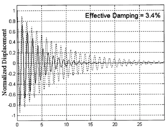
In the source code used to run this simulation, the q has been multiplied by a scaling factor deemed suitable for a SDOF system with this formulation. The reasoning is to yield an algorithm that may be altered by changing the value of q only. The r, which is the weighting associated with the feedback force, is allowed to remain at a value of 1, following the format of classical control. The scaled q is altered, to determine importance of the displacement versus the feedback force, but is also on the order of 1. Figure 5.1 shows the resulting system equivalent damping, caused by the semi-active damper feedback, for q=1.
1 --- --- ---
---Effective
bamping=
3.4%
--- ---0.4 0.6 - - - --- ---0 .4 - - - - - ----- - - - - + - - - - -~' - - - - - --O.- - -- --- --- --- -- --- -- --- -- --0.8 4---I I 0 . I - I' I' - - - -T I' - - - - I-- -1 -- - - - , - - - - -0 5 10 15 20 25Figure 5.1 System impulse response (q = 1; E, = 3.4%)
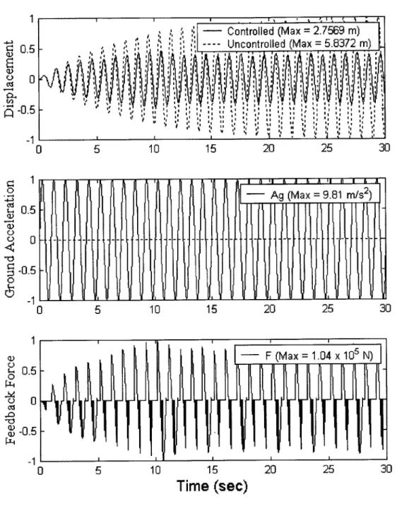
The damping is obtained by subjecting the system to an impulsive loading and monitoring the vibration decay due to feedback. The logarithmic decrement is determined from peaks of the vibration, separated by two cycles. Figure 5.2 shows the resulting system performance, for this relatively low damping and displacement weighting, to a sinusoidal ground motion input.
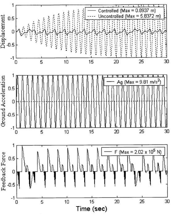
:.5 - Uncontrolled (Max 5.8372 rn) 0. 5 01 2 53 0 0 5 10 15 20 25 30 - Ag (Max = 9.81 m/s2 0.5 -1 1 1-11 0 5 10 15 20 25 30 1 -- F (Max =1.04 x 10⁵' N) 0.5 --00 PL4 0 0 -0.5 --1 0 5 10 15 20 25 30
Time (sec)
Figure 5.2 Normalized semi-active system responses to sin load (q = 1)
These graphs show a decrease of the displacement that is small relative to what is possible for the simplistic sinusoidal ground motion. Figure 5.3 illustrates a much greater decrease in this displacement and is, in fact, the greatest decrease
1
o_
. - ---- Uncontrolled (Max =5.8372 m) CI o i It IQ oi 0 -1 0 5 10 15 20 25 30 0 - Ag (Max= 9.81 n/s) IS' 0.5 0--
-- -- -- -- --- -- - - - -- --S-0.5 -1 0 5 10 15 20 25 30 1 -- F (Max =1.35 x 10⁵ N) 0.5 --oO 2 -0.5 0 5 10 15 20 25 30Time (sec)
Figure 5.3 Normalized semi-active system responses to sin load (q = 4)
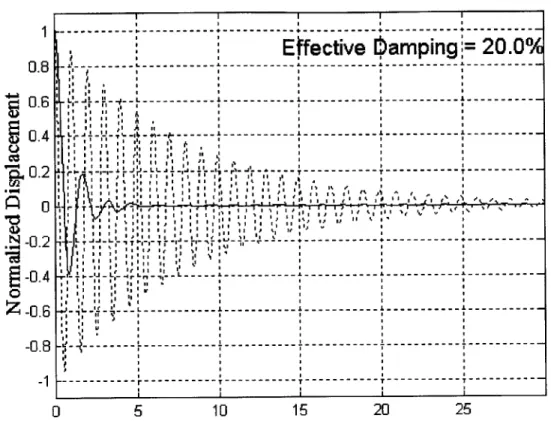
The characteristic that distinguishes this reduction and weighting is that the system is still responding in an under-damped manner, with an effective damping ratio of 20.0%. Figure 5.4 illustrates the system damping for this case, with q= 4.
Effective
[amping
=
20.0%
0.8 --- --- --- --- --- --- -I. I I I - I,- -- --0
- - - , . , , . - . , , -0.4 4 Is Is LLI r IsI I 4 I IIs I -0 .6 - -1 -L-- A - - - - - - - --- - ---- -- -- - --- --- - - -: I, II IsI -0 . --- - -- - - - -- -- -- --- - - -- --- -L - -- -- -- --- -L -- ---- -- ---0 . Is I 0 -1 --- --- ---- --- --- + --- --- --- --0 5 10 15 20 25Figure 5.4 System impulse response (q = 4; , = 20.0%)
The transition through critical damping into an over-damped system begins to occur as the q value is further increased. Figure 5.5 illustrates the over damped system response.
1 0.5 -- -- Uncontrolled (Max = 5.8372 m) , 0 0 10 15 go 20253 -- Ag (Max =9.81 m/s2) 0.5 Q- 0 -0.5 -1 0 5 10 15 20 25 30 Time (sec) 0. 00 PLI -bo IV -0.5 0 5 10 15 20 25 30
Time (sec)
Figure 5.5 Normalized semi-active system responses to sin load (q = 6)
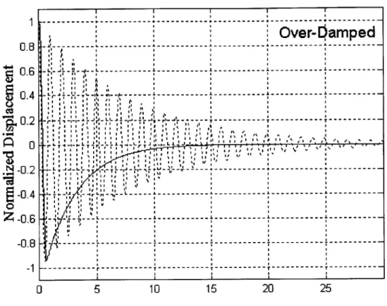
The over damped vibration decay, corresponding to this system response is illustrated in Figure 5.6. The effective damping is well over 100%
1 --- --- --- -- -- -- -- - ---- -- -- -- -- - -- -- -- -- --
---Over-bamped
0.I 0. -- - - - ---Cee II II I I I I L'. - - -- --- - - --0.4 - --- ---- - - - - --- -- - - -- -- ---- -- -0.6 - -I -I I f - I gI P If I 0 -0.4 --- + --- --- +- --- +- --- +- - --0 0 . -02 iT ' - - - - --- --- --- -- -f0.8 :--- - - --- -- A- - A- -0 5 10 15 20 25Figure 5.6 System impulse response (q = 6; Over-Damped)
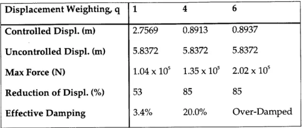
Appendix B contains several sets of graphical output for system response due to a set of 4 randomly chosen earthquakes. They are meant to illustrate the correspondence in the algorithm's performance between the sinusoidal input shown above and real input. The values obtained for the displacements and forces for the sinusoidal loading are illustrated in Table 5.2.
Table 5.2 Semi-active system performance to sin load and varying q Displacement Weighting, q 1 4 6 Controlled Displ. (m) 2.7569 0.8913 0.8937 Uncontrolled Displ. (m) 5.8372 5.8372 5.8372 Max Force (N) 1.04 x 10' 1.35 x 10⁵ 2.02 x 10" Reduction of Displ. (%) 53 85 85
Effective Damping 3.4% 20.0% Over-Damped
Table 5.4 presents these response quantities for the test set of earthquakes, which are taken from El Centro, Pocoima Dam, Taft, and Kobe. These values are based on earthquake records, acquired from the FEMA website, attached to the free NONLIN program (Appendix B). They were converted to use as input for the Matlab script attached at Appendix B. All records were provided at a time step of 0.02s, which is why the sinusoidal input accelerations were also taken at 0.02s. The scaled q values are the same as those used for the sin loading to compare performance. The earthquake ensemble has peak values as shown in Table 5.3
Table 5.3 Earthquake ensemble characteristics
Earthquake Ag max Type (m/s2)
El Centro 3.42 Early Peak, then lower accelerations Pocoima Dam 10.55 Clustered high accelerations, 0-10 s
Taft 1.76 Early Peak, then distributed reduced peak accelerations
Table 5.4 Semi-active system performance to 4 test earthquakes and varying q
Displacement 1 4 6
Weighting, q
Imperial Control Displ, m 0.1291 0.0763 0.0717 Valley, El
Centro, May Uncontrol Displ 0.1673 0.1673 0.1673 18 1940, 270 Max Force, N 4.90 x 10³ 1.15 x 10⁴ 1.60 x 10⁴
degrees
Displ Reduction, % 23 54 57
San Control Displ, m 0.2142 0.1809 0.1664
Fernando,
Pocoima Uncontrol Displ 0.2332 0.2332 0.2332 Dam, Feb 9 Max Force, N 8.15 x 10³ 2.74 x 10⁴ 3.77 x 10⁴
1971, 196
degrees Displ Reduction, % 8 22 29
Kern County, Control Displ, m 0.0399 0.0460 0.0323 Taft Lincoln
Tunnel, July Uncontrol Displ 0.0499 0.0499 0.0499 21 1952, 69 Max Force, N 1.52 x 10³ 6.96 x 10³ 7.29 x 10 3
degrees
Displ Reduction, % 20 8 35
Kobe, Japan, Control Displ, m 0.3672 0.2858 0.1772 NS
Component Uncontrol Displ 0.4274 0.4274 0.4274 Max Force, N 1.40 x 10⁴ 4.32 x 10⁴ 4.01 x 10⁴
5.2 Adaptive Control 5.2.1 Overview
The adaptive control algorithm is physically implemented in a manner similar to the semi-active algorithm. The system will begin with a zero feedback force, which is the passive state of the semi-active damper. The stiffness will be in a state determined optimal from passive design techniques illustrated in Chapter 2. Sensors will be active at all times, recording system and ground motion. When at least two data points of motion have been obtained, the system will begin to determine the combination of optimal feedback force and optimal discrete stiffness.
These values will each be subject to known constraints. The damper feedback will be restrained to operate only when the system is in motion and will be limited by device capacity. The stiffness device is allowed to jump by discrete quantities determined by the amount and type of variable stiffness devices in use. The state predictor uses a finite difference method to approximate the equilibrium equation. The dynamic forcing is assumed to be constant over the evaluated interval, which is a single time step.
5.2.2 Numerical Results
Testing of the proposed adaptive algorithm required establishment of a numerical single degree of freedom model. The parameters are similar to those chosen for the semi-active control algorithm, with the exception of the adaptive stiffness quantities. The chosen parameters are shown in Table 5.5.
Table 5.5 Adaptively controlled SDOF properties
Parameter Value
Mass 5,000 kg
Percent Damping 2 % Passive Natural Period 1 s
Passive Stiffness 200,000 N/m Maximum Feedback 200,000 N Force
The stiffness values used by the control algorithm will be illustrated with the system response graphs. To better understand the alteration of stiffness, the 6 possible discrete stiffness states will be represented as shown in Table 5.6. It was desired to give a range of stiffness values that are possible to obtain with implementation of a real AVS system.
Table 5.6 System discrete stiffness values (numbers used for graphs)
began with the sinusoidal loading, to readily test the feedback and adaptive system without impulse loadings. The sin loading was established with a peak acceleration of 9.81 m/s2 and a frequency of 2n. An additional alteration, chosen
for the adaptive system, was to lower the capacity of the semi-active feedback damper, specifying F. = 2 x 10' N. This reduction was chosen to illustrate one situation where adaptive control would be chosen over active control. Often, the costs associated with scaling a device, like the semi-active dampers, are prohibitive. In that case, the option of inserting other low cost control devices
should be considered.
The first test was to set all 3 of the a weights equal to 1. This decision was made because the scaling process is quite complex with three weights and non-dimensional parameters to be controlled. Figure 5.7 illustrates this test for the sinusoidal input loading.
1 UU 0.56---- Un controlled (Max =5.8372 mn) 0 -0.5 --1 0 5 10 15 20 25 30 -- F (Max =2.04 x 10³ N) 0.5 -0 -b4 -0.5 -1 0 5 10 15 20 25 30 n6 - -- K (Max =2.00 x 10⁵ N) -1 0 ' ' ' 0 5 10 15 20 25
Time (sec)
Figure 5.7 Adaptive system responses to sin load (CF=c u=CUk=1 -0)
The responses illustrate several performance trends. The displacement is not weighted heavily enough to be significantly altered from the uncontrolled case, with only a 2% reduction in peak displacement. Additionally, the weighting
means that all feedback occurs from activation of the semi-active damping mechanism. Figure 5.8 illustrates an increase in the weighting of the system displacement with the weights for the two control systems kept at 1.
5 10 15 20 25 30
5 10 15 20 25 30
5 10 15 20 25
Time (sec)
Adaptive system responses to sin load (CF=Ck=1 -0; CCu= 0)
1 ~05 00 -0.5 -1'L 0 1 0.5 0 0 W -0.5 -11. 0 Un -
4
02 0 -0 Figure 5.8The interesting result seen in Figure 5.8 is the alteration of the system stiffness and the improved performance caused by this alteration. The graph also illustrates a critical time at which the AVS is first activated. To understand why this happens, the formulation must be considered.
The cost function, that is minimized, uses non-dimensional parameters, of which the variation of u with respect to u allowable is one. This cost function is independently evaluated at each time, with only the system state as input. At or near 8 seconds, the algorithm determines that it is now advantageous to affect a change in the system stiffness to minimize the system displacement. This determination of optimal system responses continues for each time step, with results shown in Figure 5.8.
The next case shown in Figure 5.9 illustrates a further increase in the displacement weighting, with ac equal to 1000. It is noted that the displacement is almost entirely eliminated for this sinusoidal ground motion.
0.5 0 -0.5 -1 1 0.5 0 0 S-0.5 gn6 ..zJ 4 2 0 0 5 10 15 20 25 30 - F (Max = 7.05 x 10⁴ N) 0 5 10 15 20 25 30 K (Max = 2.00 x 10⁵N) -0 5 10 15
Time (sec)
20 25Figure 5.9 Adaptive system responses to sin load (QF=CUk=1 -0; cu= 000)
Although the entire system performance is improved, with a 97% reduction of peak displacement, the stiffness alteration is not used, decreasing the efficiency of the control method in 2 ways. First, the feedback force is necessarily higher,
- . -~ -- - Uncontrolled (Max = 5.8372 rn).