© Sina Gilassi, 2020
Optimized Modeling of Membrane Gas Phase Separation
Processes
Thèse
Sina Gilassi
Doctorat en génie chimique
Philosophiæ doctor (Ph. D.)
Optimized Modeling of Membrane Gas Phase Separation
Processes
Thèse
Sina Gilassi
Sous la direction de :
Seyed Mohammad Taghavi, directeur de recherche
Denis Rodrigue, codirecteur de recherche
Serge Kaliaguine, codirecteur de recherche
ii
Résumé
Le schéma traditionnel d'utilisation de l'énergie est désormais considéré comme un problème sérieux en raison de sa relation directe avec le changement climatique. Actuellement, notre dépendance vis-à-vis des combustibles fossiles augmente de façon spectaculaire, ce qui peut être attribué à la croissance de la population mondiale et à la forte demande d'énergie pour le développement économique. Ce modèle semble être préférable uniquement pour une économie florissante, mais ses perspectives pour les générations futures seront sans aucun doute décevantes. Dans ce scénario, un volume gigantesque de CO2 produit par la combustion des combustibles fossiles dans les industries chimiques, les cimenteries et les centrales électriques, est rejeté de manière irresponsable dans l'atmosphère. Il ne fait aucun doute qu'une telle exploitation des combustibles fossiles nous conduit à des catastrophes environnementales sans précédent en ce qui concerne l'émission de CO2, qui est le principal contributeur aux gaz à effet de serre (GES). L'une des solutions disponibles pour faire face à cette situation critique est de moderniser les centrales existantes qui émettent du CO2 avec des technologies de capture et de stockage du carbone (CSC) afin de lutter systématiquement contre le changement climatique. Toutefois, les technologies actuelles de CSC présentent encore des problèmes techniques et des limites opérationnelles qui entraînent un surcoût pour les dépenses d'une usine et une augmentation de sa consommation d'énergie.
La technologie membranaire est actuellement considérée comme une méthode de séparation prometteuse pour la séparation des gaz en raison de la simplicité de son procédé et de son mécanisme écologique. Par rapport aux autres méthodes de séparation, cette technologie est encore en cours de développement. Actuellement, la recherche se concentre sur l'amélioration des caractéristiques des membranes afin de faire face à un compromis bien connu entre la perméabilité et la sélectivité décrit par les graphiques de Robeson. Cette approche pourrait viser à commercialiser cette technologie plus efficacement dans le domaine de la séparation des gaz, tandis qu'une technologie d'absorption à base d'amines sera encore utilisée de manière dominante à cette fin pendant plusieurs années. Malgré cela, il est également nécessaire d'évaluer la performance des membranes fabriquées pour la séparation de différents mélanges de gaz avant de les utiliser pour des projets industriels réalistes. Pour ce faire, un outil de simulation est nécessaire pour prédire la composition des composants gazeux dans les flux de produits du rétentat et du perméat dans différentes conditions de fonctionnement. Ainsi, au chapitre 1, un modèle fiable est développé pour la simulation de la séparation des gaz à l'aide de modules de membranes à fibres creuses. Ensuite, ce modèle permet d'identifier les propriétés requises de la
iii
membrane, ce qui permet d'obtenir des performances intéressantes pour le module. Un procédé membranaire à plusieurs étapes est nécessaire pour atteindre les spécifications du produit qui sont une pureté et une récupération élevées du CO2 dans le cas de projets de capture du CO2. Dans ce cas, au chapitre 2, un modèle d'optimisation est proposé pour déterminer les valeurs optimales des paramètres de fonctionnement pour chaque étape et surtout pour déterminer une disposition optimisée à différents taux de récupération tout en minimisant le coût de la capture du CO2. Dans le chapitre 3, nous comparons les performances de séparation de la technologie membranaire et du procédé d'absorption enzymatique en effectuant plusieurs analyses technico-économiques. Cette approche vise à démontrer la viabilité technique et l'efficacité économique de ces méthodes pour la modernisation d'une centrale électrique de 600 MWe par rapport aux procédés traditionnels d'absorption à base d'amines. Enfin, au chapitre 4, un système hybride est présenté en combinant les procédés d'absorption membranaire et enzymatique pour capturer le CO2 des gaz de combustion d'une centrale électrique de 600 MWe. Ce système hybride est ensuite évalué pour révéler la faisabilité du procédé et pour étudier les performances de séparation en partageant la capture partielle du CO2 entre ces deux unités de séparation. Dans l'ensemble, cette thèse de doctorat contribue à tirer parti de la fusion de la technologie membranaire avec d'autres méthodes de séparation conventionnelles telles que le procédé d'absorption enzymatique pour faciliter plus rapidement son intégration industrielle et sa commercialisation sur le marché de la séparation des gaz.
iv
Abstract
The traditional pattern of energy use is now regarded as a serious problem due to its direct relationship to the climate change. Currently, our dependency on fossil fuels is dramatically increasing which can be attributed to the world population growth and heavy energy demand for economic development. This model appears to be preferable only for flourishing economy but undoubtedly its outlook for the future generations will be disappointing. Under this scenario, a gigantic volume of CO2 produced by burning the fossil fuels in chemical industries, cement manufactures, and power plants, is recklessly released in the atmosphere. Undoubtedly, such exploitation of the fossil fuels is bringing us further to unprecedented environmental disasters pertaining to the emission of CO2 which is the major contributor to the greenhouse gases (GHGs). One of the available solutions to deal with this critical situation is to retrofit existing CO2 emitter plants with carbon capture and storage (CCS) technologies in order to systematically combat with the climate change. However, the current CCS technologies still have technical issues and operational limitations resulting in incurring extra cost to a plant’s expenditures and increasing its energy consumption.
Membrane technology is currently regarded as a promising separation method for gas separation due to its process simplicity and eco-friendly mechanism. In comparison to other separation methods, this technology is still under progress. Currently, the research focus is on the enhancement of membrane characteristics in order to deal with a well-known trade-off between permeability and selectivity described by Robeson plots. This approach might aim at commercializing this technology more efficiently in the gas separation area while an amine-based absorption technology will still be dominantly utilized for this purpose for several years. Despite this, it is also needed to evaluate the performance of fabricated membranes for the separation of different gas mixtures prior to utilizing for realistic industrial projects. To do so, a simulation tool is required to predict the composition of gas components in retentate and permeate product streams under different operating conditions. Thus, in Chapter 1, a reliable model is developed for the simulation of gas separation using hollow fiber membrane modules. Later, this model allows identifying the required membrane properties hence, resulting in module performances of interest. A multi-stage membrane process is required to hit product specifications which are high CO2 purity and recovery in the case of CO2 capture projects. In this case, an optimization model is proposed in Chapter 2 to determine the optimal values of operating parameters for each stage and more importantly to determine an optimized layout at different recovery rates while CO2 capture cost is minimized. In Chapter 3, we compare the separation performance of
v
membrane technology and the enzymatic-absorption process through performing several techno-economic analyses. This approach aims at demonstrating the technical viability and techno-economic efficiency of these methods for retrofitting to a 600 MWe power plant compared to traditional amine-based absorption processes. Finally, a hybrid system is introduced in Chapter 4 by combining membrane and enzymatic-absorption processes to capture CO2 from flue-gas of a 600 MWe power plant. This hybrid system is then assessed to reveal the process feasibility and to investigate separation performance through sharing partial CO2 capture between these two separation units. Overall, this PhD thesis contributes to leverage the merge of membrane technology with other conventional separation methods such as the enzymatic-absorption process to more rapidly facilitate its industrial integration and commercialization in the gas separation market.
vi
Table of contents
Résumé ... ii Abstract ... iv Table of contents ... vi List of Tables ... ix List of Figures ... x Acknowledgements ... xiv Foreword ... xv Introduction ... 1I.1 Gas separation ... 1
I.1.1 Conventional separation methods ... 2
I.1.2 Membrane technology ... 2
I.1.3 Hybrid process ... 4
I.2 Objectives and research contributions ... 5
I.3 Structure of this thesis ... 5
Simulation of Gas Separation Using Partial Element Stage Cut Modeling of Hollow Fiber Membrane Modules ... 8 1.1 Résumé ... 8 1.2 Abstract ... 8 1.3 Introduction ... 9 1.4 Modeling Background ... 10 1.5 Model development ... 13 1.5.1 Model assumption ... 13 1.5.2 Modeling algorithm ... 14
1.5.3 Co-current flow (shell side feed) configuration ... 14
1.5.4 Model validation ... 19
1.6 Case study: oxygen enrichment ... 24
1.7 Case study: natural gas processing ... 28
1.8 Use of the model in guiding experimental membrane development ... 32
1.9 Conclusion ... 35
Optimizing Membrane Module for Biogas Separation ... 38
2.1 Résumé ... 38
2.2 Abstract ... 38
2.3 Introduction ... 39
vii
2.4.1 Superstructure membrane network ... 44
2.4.2 Model Formulation ... 45
2.5 Case study: biogas upgrading process ... 52
2.5.1 Optimized biogas process ... 53
2.5.2 Effects of CO2 content and CH4 recovery on upgrading cost ... 59
2.5.3 Effect of CO2/CH4 selectivity on upgrading cost ... 61
2.5.4 Effect of membrane cost on upgrading cost ... 63
2.6 Conclusion ... 67
Techno-Economic Evaluation of Membrane and Enzymatic-Absorption Processes for CO2 Capture from Flue-Gas ... 72
3.1 Résumé ... 72
3.2 Abstract ... 72
3.3 Introduction ... 73
3.3.1 With or without the MEA solution: that is the question! ... 78
3.3.2 Enzymatic reaction system ... 83
3.3.3 Objective of this study ... 84
3.4 Modeling and optimization of the membrane process ... 84
3.5 Modeling of enzymatic-absorption process ... 86
3.5.1 Process description ... 86
3.5.2 Modeling approach ... 87
3.6 Optimization outline to minimize CO2 capture cost... 88
3.6.1 Enzymatic-absorption process ... 88
3.6.2 Cost model... 89
3.7 Results and discussion ... 90
3.7.1 Process description ... 90
3.7.2 Optimized membrane process ... 90
3.7.3 Optimized enzymatic-absorption process ... 98
3.8 Conclusion ... 106
Techno-Economic Analysis of a Hybrid System for Flue-Gas Separation: Combining Membrane and Enzymatic-Absorption Processes ... 108
4.1 Résumé ... 108
4.2 Abstract ... 108
4.3 Introduction ... 109
4.3.1 Performance, limits, and potentials of conventional separation methods ... 110
4.3.2 Hybrid systems for flue-gas separation ... 114
4.3.3 Membrane-Absorption (MA) hybrid system ... 116
viii
4.4 Modeling and optimization of hybrid system ... 119
4.4.1 Membrane permeation model ... 119
4.4.2 Enzymatic-absorption model ... 119
4.4.3 Optimization method ... 120
4.5 Results and discussion ... 121
4.5.1 Process description ... 121
4.5.2 Required solvent for CO2 capture in the hybrid process ... 122
4.5.3 Hybrid process energy analysis ... 125
4.5.4 Separation efficiency of the hybrid process ... 129
4.5.5 Cost analysis of CO2 capture ... 134
4.6 Conclusion ... 136
Conclusion... 140
Annexe A Chapter 1 supplementary materials ... 145
A.1 Cross-flow configuration ... 145
A.2 Counter-current flow configuration ... 147
A.3 Heat Transfer Analysis ... 149
Annexe B Biogas Upgrading and Optimization ... 153
B.1 Abstract ... 153
B.2 Introduction ... 153
B.3 Biogas production and uses ... 155
B.4 Biogas upgrading methods ... 159
B.4.1 Absorption ... 159
B.4.2 Adsorption ... 163
B.4.3 Cryogenic distillation ... 165
B.4.4 Membrane technology ... 166
B.4.5 Hybrid systems ... 168
B.5 Case study: biogas membrane separation ... 174
B.6 Conclusions and perspectives ... 178
ix
List of Tables
Table 1.1 The properties of the experimental hollow fiber modules and feed conditions. ... 20
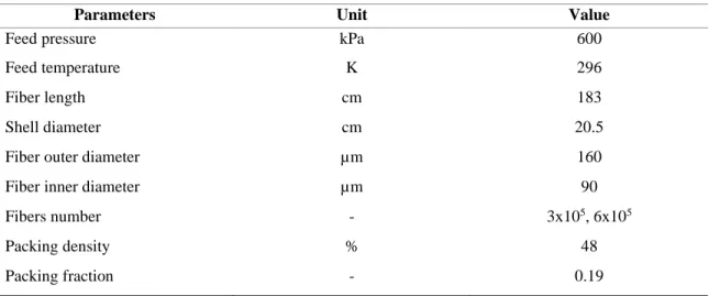
Table 1.2 Parameters used for the modeling of the O2 production unit. ... 25
Table 1.3 Summary of the modeling results of a two-stage membrane separation unit for O2 production. ... 28
Table 2.1 Techno-economic parameters and assumptions applied to the optimization case. ... 52
Table 2.2 Operating and feed conditions used for the optimization cases. ... 53
Table 2.3 Summary of the techno-economic analysis of optimized membrane separation processes. ... 67
Table 3.1 Flue-gas properties used for the optimization problem. ... 87
Table 3.2 Techno-economic analysis of CO2 capture from a 600 MWe power plant using a two-stage membrane process. ... 94
Table 3.3 Comparison of separation performance of the optimized process with different membrane processes. ... 97
Table 3.4 Input data used for optimization of the enzymatic-absorption process. ... 98
Table 3.5 Summary of techno-economic analysis of CO2 capture using the enzymatic-absorption process. ... 105
Table 4.1 Flue-gas properties used for the optimization problem. ... 122
Table 4.2 Summary of techno-economic analysis of CO2 capture using the hybrid process (ICC 30%, 0.3 bar). ... 135
Table 4.3 Techno-economic results of hybrid, standalone membrane and enzymatic-absorption processes (CAP 90%). ... 136
Table B.1 Typical biogas composition [23]. ... 156
Table B.2 Environmental requirements for AD systems [73]. ... 157
Table B.3 Characteristics of different fuel gases [235]. ... 158
Table B.4 Pipeline specifications when supplying upgraded biogas to the natural gas grid [23]. ... 159
x
List of Figures
Figure 1.1 Schematic diagram of a co-current flow membrane separation module, and the
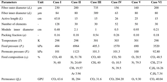
feed and permeate flows in the first and two successive elements... 15 Figure 1.2 Comparison of modeling results with the experimental data of: (a) Sidhoum,
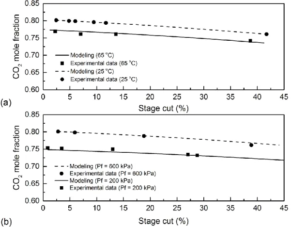
Sengupta, and Sirkar [62], (b) Pan [36]... 21 Figure 1.3 Comparison of modeling results with the experimental data of Tranchino et al.
[61], (a) at two different feed temperatures (25 and 65°C), (b) at two different feed pressures
(200 and 600 kPa). ... 22 Figure 1.4 Comparison between modeling results and the experimental data of: (a) Sada et
al. [65], (b) Feng et al. [63]. ... 23 Figure 1.5 Comparison between case VI modeling results and the experimental data of Pan
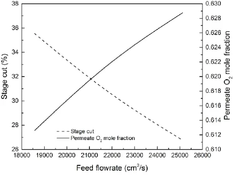
[36]. ... 24 Figure 1.6 Separation performance in terms of stage cut and O2 mole fraction as a function
of module feed flow rate: (a) Pf = 600 kPa, Pp = 100 kPa, number of fibers = 3x10⁵, (b) Pf =
600 kPa, Pp = 100 kPa, number of fibers = 6x10⁵. ... 26 Figure 1.7 Separation performance in terms of stage cut and O2 mole fraction as a function
of module feed flow rate (Pf = 600 kPa, Pp = 100 kPa, number of fibers = 6x10⁵). ... 27 Figure 1.8 Effect of different CO2/CH4 selectivities on the CH4 retentate mole fraction and
total membrane area, (a) CO2 content in feed = 10 mol.%, (b) CO2 content in feed = 25 mol.%.
... 30 Figure 1.9 Effect of different CO2/CH4 selectivities on the CH4 retentate mole fraction and
total membrane area: (a) CO2 content in feed = 50 mol.%, (b) CO2 content in feed = 75 mol.%.
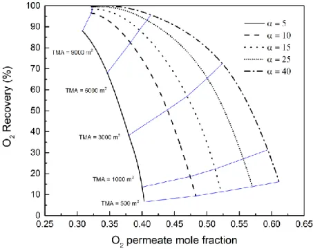
... 31 Figure 1.10 Process flow diagram of the natural gas purification using two membrane units. ... 32 Figure 1.11 Effect of O2/N2 selectivity on the O2 permeate mole fraction and O2 recovery in
a single membrane unit, (N2 permeance = 1.8 GPU, O2 permeance variable). ... 33 Figure 1.12 Effect of O2/N2 selectivity on the O2 permeate mole fraction and O2 recovery in
a single membrane unit, (O2 permeance = 9.3 GPU, N2 permeance variable). ... 34 Figure 1.13 Effect of O2/N2 selectivity on the O2 permeate mole fraction and O2 recovery in
a single membrane unit, (N2 permeance = 3.6 GPU, O2 permeance variable). ... 34 Figure 2.1 Schematic diagram of the optimization of a three-stage separation process. ... 45 Figure 2.2 Schematic flow diagram of an optimized two-stage separation process at 10%
biogas CO2 content. ... 54 Figure 2.3a Relation between the FA index and results of the optimization problem (UMn, φ)
outlined in Table 2.2 (Ultem 1000 membrane, QCO2 = 86.3 GPU, QCH4 = 2.60 GPU). ... 57 Figure 2.3b Relation between FA index and separation unit volume with module lengths of
50 and 100 cm. ... 57 Figure 2.4 Relation between the inlet gas flowrate and unit modules number when the module
diameter is set to 12.7 cm (5 inches). ... 58 Figure 2.5 Effects of module diameter (5 and 12 in) on the required UMn over a range of unit
feed flowrate. ... 59 Figure 2.6 Effects of CO2 feed content changes on the biogas separation cost. ... 60 Figure 2.7 Effect of CH4 recovery improvement on the gas separation cost when the CO2 feed
content is 40%. ... 61 Figure 2.8 Effects of change in CO2/CH4 selectivities on the biogas separation cost for the
following membrane CO2/CH4 selectivity and CO2 permeance: a) 33.2, 86.3; b) 66.4, 86.3;
xi
Figure 2.9 Effects of membrane cost (25 and 50 $/m2) on the optimized separation cost, membrane area and feed pressure (CO2/CH4 selectivity of 33.2 with a CO2 permeance of 86.3
GPU and a feed composition of 40% CO2). ... 65
Figure 2.10 Effect of the membrane cost (25 and 50 $/m2) on the optimized separation cost, membrane area and feed pressure (CO2/CH4 selectivity of 66.4 with a CO2 permeance of 172.6 GPU, and a feed composition of 40% CO2). ... 66
Figure 3.1 Process flow diagram of a multi-structure membrane process used in the process optimization. ... 86
Figure 3.2 Process flow diagram of an enzymatic-absorption process for flue-gas treatment. ... 87
Figure 3.3 Optimized membrane layout for 90% CO2 capture from flue-gas. ... 91
Figure 3.4 Effects of CO2 capture on the purchase cost of the equipment in the optimized two-stage membrane process. ... 92
Figure 3.5 Effects of CO2 capture on the membrane process costs. ... 95
Figure 3.6 Effects of CO2 capture on the energy consumption of equipment in the membrane process. ... 96
Figure 3.7 a) Effects of solvent flowrate on the CO2 capture in the enzymatic-absorption process (example of a 600 MWe power plant), b) Effects of the lean CTB index on the heat of CO2 regeneration (90% CO2 capture). ... 100
Figure 3.8 Heat analysis of the desorption process at different lean CTB level (90% CO2 capture). ... 101
Figure 3.9 Relation between the lean CTB and performance of vacuum system. ... 103
Figure 3.10 Effects of the lean CTB level on the electricity loss of plant. ... 104
Figure 4.1 Process flow diagram of a hybrid process including pre-treatment, membrane, and enzymatic-absorption units. ... 121
Figure 4.2 Relation between the L/G ratio in the absorber and total CO2 capture rate in the hybrid process. ... 124
Figure 4.3 Variation of the lean and rich CTB indexes at different L/G ratio in the single and hybrid enzymatic-absorption processes. ... 125
Figure 4.4 Effects of lean CTB index and ICC in the hybrid process on the heat of CO2 recovery in the stripper column. ... 126
Figure 4.5 Effects of vacuum pressure in the stripper and ICC in the hybrid process on electricity loss for a 600 MWe power plant. ... 127
Figure 4.6 Electricity loss by the vacuum systems at different pressure setpoints in the enzymatic-absorption process. ... 128
Figure 4.7 Comparison between the circulation rate of solvent between absorption and desorption in the standalone enzymatic-absorption and hybrid processes. ... 129
Figure 4.8 Relation between the extent of CO2 capture and electricity loss for a standalone two-stage membrane unit integrated into a 600 MWe power plant (Calculated from results in [218]). ... 131
Figure 4.9 Overall electricity loss of the hybrid process at different operating and design conditions. ... 133
Figure A.1 Schematic diagram of a cross-flow membrane separation module. ... 145
Figure A.2 Schematic diagram of the first element in contact with the feed gas for the cross-flow configuration. ... 146
Figure A.3 Schematic diagram of two successive elements in the cross-flow configuration. ... 147
Figure A.4 Schematic diagram of a counter-current flow membrane separation module. ... 147
xii
Figure A.6 Schematic diagram of two successive elements in the counter-current flow
configuration. ... 148
Figure A.7 Schematic diagram of heat transfer in a fiber [47]. ... 151
Figure B.1 Schematic diagram of the conversion of organic matter to CH4, CO2 and other biogas components. ... 156
Figure B.2 The process flow diagram of acid gas removal using amine scrubbing. ... 160
Figure B.3 The flow diagram of a water scrubbing process using scrubber and regeneration units. ... 161
Figure B.4 The flow diagram of an organic solvent scrubbing process. ... 163
Figure B.5 The process flow diagram of a pressure swing adsorption unit for biogas upgrading... 164
Figure B.6 The flow diagram of a cryogenic distillation process used for biogas upgrading. ... 165
Figure B.7 The schematic flow diagram of various single stage membrane units. ... 167
Figure B.8 Two stage membrane configuration. ... 168
Figure B.9 Three stage membrane configuration. ... 168
Figure B.10 The schematic flow diagram of a hybrid process including membrane and chemical absorption units. ... 169
Figure B.11 The schematic flow diagram of hybrid systems including membrane and a, b) pressurized water scrubbing processes, c, d) amine absorption processes, e) cryogenic distillation ... 171
Figure B.12 Annual cost of biogas upgrading processes for a gas flow rate of 1000 m3 (STP)/h. ... 172
Figure B.13 The flow diagram of another hybrid process including TSA and membrane units for the separation of CO2 from biogas. ... 173
Figure B.14 The schematic flow diagram of the hybrid separation process. ... 173
Figure B.15 Relations between the CH4 mole fraction, membrane separation area and total cost at different pressures. ... 176
Figure B.16 Relations between the CH4 mole fraction, membrane separation area and CH4 loss at different pressures. ... 176
Figure B.17 Relations between CH4 mole fraction, total membrane area and total cost for three different pressures (3, 4.5 and 6 bars). ... 177
Figure B.18 Relations between the CH4 mole fraction and CH4 loss for two membrane units. ... 178
xiii
xiv
Acknowledgements
I would like to express my deep gratitude and appreciation to Prof. Serge Kaliaguine, for the patient guidance, encouragement and advice he has provided throughout my time as his student. I would also like to thank Prof. Seyed Mohammad Taghavi and Prof. Denis Rodrigue for their academic guidance, support and encouragement throughout my doctoral program at Laval University.
I would like to thank the Chemical Engineering department staffs for all the technical and administrative assistance that I received during the entire period of my study. Finally, I would like to thank the Natural Sciences and Engineering Research Council (NSERC) of Canada and the Mathematics of Information Technology and Complex Systems (MITACS) programme for their financial support.
xv
Foreword
This thesis consists of four chapters presented as articles in the insertion form. The three chapters of the thesis are published, and Chapter 4 is now submitted and currently under review. The introduction and conclusion sections are original, and they have never been published before. The articles are listed below:
Chapter 1: Gilassi, S., Taghavi, S.M., Rodrigue, D., and Kaliaguine, S. Simulation of gas separation
using partial element stage cut modeling of hollow fiber membrane modules. AIChE Journal, 2018.
64(5): p. 1766-1777.
Chapter 2: Gilassi, S., Taghavi, S.M., Rodrigue, D., and Kaliaguine, S. Optimizing membrane module
for biogas separation. International Journal of Greenhouse Gas Control, 2019. 83: p. 195-207.
Chapter 3: Gilassi, S., Taghavi, S.M., Rodrigue, D., and Kaliaguine, S. Techno-Economic Evaluation
of Membrane and Enzymatic-Absorption Processes for CO2 Capture from Flue-Gas Separation and
Purification Technology, 2020: p. 116941.
Chapter 4: Gilassi, S., Taghavi, S.M., Rodrigue, D., and Kaliaguine, S. Techno-Economic Analysis of
a Hybrid System for Flue-Gas Separation: Combining Membrane and Enzymatic-Absorption Processes. Chemical Engineering and Processing: Process Intensification, 2020: p. Under review.
Furthermore, a review of the current gas separation methods available for biogas treatment process was written as a book chapter and published by Nova Science (ISBN: 978-1-53612-787-4).
Gilassi, S., Taghavi, S.M., Kaliaguine, S., and Rodrigue, D., “Biogas Upgrading and Optimization”
In Biogas: Production, Applications and Global Developments, A. Vico, et al., Editors. 2017, Nova Science: USA.
In all cases, I performed the literature review, the numerical calculations and the data analysis, as well as writing the first draft of the complete manuscript. Prof. Kaliaguine, Taghavi and Rodrigue helped with the data analysis and discussion of the results, as well as making the necessary corrections in the documents.
1
Introduction
I.1 Gas separation
Gas processing is commonly regarded as a critical step in most chemical plants and industrial manufactures in order to separate impurities and undesired materials, to ultimately reach a target product as per standard quality requests. Statistics demonstrate a rising trend in the global energy demand due to rapid growth of population, modernization, and economy. This scenario might be translated to a serious challenge of choosing an energy source which has lower impacts on the environment. At present, natural gas as a clean energy-future source is dominating the global market compared to other fossil fuels. Thus, great attentions have been made to facilitate the transition of this strategic energy source in the world while the effects of fossil fuels (oil, gas, and coal) combustion on climate change is undeniable. Raw natural gas which contains carbon dioxide (CO2) usually ranging from 10 to 60% depending on the depth and location of a well head, needs to be treated prior to injecting into natural gas grids or using for other applications. In recent years, numerous attempts have also been made to decrease the level of dependency on the fossil fuels through using sustainable and renewable energy sources. Accordingly, biogas production has come into effects as a solution in many countries to cope with the coming energy crisis. In this way, a large number of fermentation plants have been constructed especially in Europe and Asia Pacific to produce biogas by anaerobic digestion (AD) of biodegradable organic materials, enriched in methane (CH4). The treatment process is also necessary as the biogas product might contain a trace of contaminating substances (halogen, organic silicon, and aromatic compounds) and acid gases (CO2 and H2S) depending on materials fed to anaerobic digesters or bioreactors. Likewise, hydrogen (H2) is considered as a promising energy source, which can be produced by steam reforming of natural gas in a reformer at high temperature and pressure in presence of a catalyst (usually nickel). Then, the final product, the so-called syngas, which also comprises undesired components including CO and CO2, needs to be treated before use for other applications. Despite all initiatives and strategies to take advantage of cleaner energies such as solar, wind, and nuclear, natural gas still remains a major energy source in the world. Power plants are currently the main consumers of natural gas for generating electricity. Following combustion in reboilers, an exhaust gaseous mixture including nitrogen (N2) and CO2, known as flue-gas, requires treatment before releasing in the atmosphere. Similarly, cements plants are known as CO2 emitters owing to the use of fossil fuels for the production of clinker inside rotary kilns. In all the above-mentioned cases, gas separation process is compulsory to capture CO2, not only to avoid technical issues but also to comply with environmental rules and regulations. This scenario, which is described in the United Nations Framework Convention on Climate Change (UNFCCC), is then considered as
2
one of the promising paths to deal with climate change. As such, CO2 capture and storage (CCS) is a technically feasible strategy to reduce the emission of CO2 as the dominant contributor to the greenhouse gases (GHGs), form large emitting sources. The CCS strategy consists of one of three main approaches. In the pre-combustion process, the fossil fuels are initially converted into a clean-burning gas enriched in H2, and then removing the remaining CO2, whereas the post-combustion process aims at removing the CO2 from flue-gas after the combustion of the fossil fuels. In the oxy-fuel combustion process, burning the fossil oxy-fuels in the presence of pure oxygen (O2) is performed and then the CO2 generated is finally captured at lower cost since it is not diluted in atmospheric nitrogen [1, 2]. Overall, the post-combustion process appears to be the most successful approach as resulting in a better retrofitting to the existing industrial sectors including raw natural gas and biogas treatment units, as well as cement manufacturers and power plants [3].
I.1.1 Conventional separation methods
The conventional post-combustion process may consist of absorption, adsorption, and cryogenic distillation technologies but so far none of them has offered satisfactory outcome for CO2 capture prospects. The absorption process is preferable to be used for treating a gas mixture containing low CO2 concentration. The capture cost is then estimated at a range of 40-100 $/ton CO2 for CO2 recovery higher than 90% [4]. This process seems to be less economically and environmentally attractive due to its high energy requirement for CO2 recovery and traditional dependency on amine solutions [5]. In comparison, the adsorption process is eco-friendlier as removing CO2 by binding it temporarily on the surface of a solid adsorbent. Cryogenic distillation allows capturing CO2 based on the thermodynamic properties of a gas mixture and being moreover independent of the type of absorbent or adsorbent. Thus, numerous researches have been performed not only to enhance the current performance of the above-mentioned processes but also to exploit other promising separation methods.
I.1.2 Membrane technology
This technology is not developed enough compared to the above-mentioned separation methods to be deployed for industrial-scale CO2 capture [6]. However, it has comparatively a more straightforward separation mechanism in that gas components in a mixture pass through a thin membrane layer depending on their permeation abilities. Thus, this mechanism can be easily extended to separate different gas mixtures such as CO2/CH4, CO2/N2, CO2/H2, and O2/N2. This separation method initially appears to have no technical barrier for process scale-up and operation for a typical CO2 removal project. As a result, numerous experimental works have been conducted in order to fabricate membranes with excellent separation characteristics. This might simply increase membrane
3
permselectivity and reinforce its chemical and physical stabilities under different operating conditions. In fact, this path would conceptualize a well-known trade-off between selectivity and permeability described by Robeson plots [7]. A few commercial membranes are currently available on the market and thus, this situation has resulted in some commercialization of the membrane technology for CO2 capture. Under this scenario, using a single-stage membrane process for efficient capture of CO2 is certainly not sufficient. Undoubtedly, a large separation area would also be required for industrial separation projects to reach high CO2 purity and recovery while using current commercial and even advanced membranes. It is therefore needed to take advantage of multiple membrane-based separation modules in parallel and/or in series. For simulation of such a process, a robust model needs to be used to predict the performance of each unit under different operating conditions. The desired model may be developed on the basis of the solution-diffusion theory, to consider the effects of parameters such as gas permeability and separation area for various membrane module types. Obviously, the result of modeling allows portraying a realistic outlook on the separation performance of fabricated membranes for different gas mixtures. This approach also allows preparing a practical guideline for experimentalists in order to modify individual gas permeances for desired membrane types and see their effects on separation process efficiency. This approach certainly narrows the gap between experimental works and industrial-scale CO2 capture projects by developing an optimization model to find the optimal values of decision variables. Numerous studies on the optimization of multi-stage membrane separation systems were carried out to evaluate the effect of using different membrane types on CO2 removal performance [8-10]. In most cases, the main objective was to minimize the cost of CO2 separation through manipulating decision variables in pre-design process layouts. This approach certainly fails to find a global optimum as a limited number of process layouts is considered for optimization search. It is therefore necessary to deploy a more robust optimization approach to deal with a superstructure membrane-based separation system. Thus, this new approach will allow determining the optimal process by considering all possible layouts in a multi-stage superstructure membrane network while the CO2 separation cost is minimized. The optimization model is then used to specify the footprint of each separation stage including required number and size of hollow fiber membrane modules in a realistic industrial case. Under this scenario, a techno-economic analysis can be performed to more accurately present the current state of membrane technology compared to other CO2 capture methods. It is then expected that this approach is precisely designed to resolve technical limitations and remove economic barriers in the face of better commercialization of membrane technology.
4
I.1.3 Hybrid process
A membrane separation process appears to be more attractive due to its simplicity compared to an amine absorption process which is currently dominating the CO2 separation market. This superiority might be taking advantage of an interesting idea to incorporate the membrane technology into a hybrid separation system, combining it with other separation methods. In turn, the hybrid system would benefit from advantages of the incorporated processes in order to either reduce CO2 capture cost or to solve existing technical issues of individual processes. Few studies have been conducted to precisely design and evaluate such a hybrid system in CO2 separation projects. For example, Belaissaoui et al. [11] proposed a hybrid membrane-cryogenic process to remove CO2 from flue-gas of a power plant. In this case, the heat requirement for CO2 recovery was then estimated at 1.4-3.7 GJ/ton CO2 captured, while CO2 mole fraction was varied in the permeate product. In another case, Kundu et al. [12] also suggested a hybrid process through combining membrane and absorption systems to remove CO2 from a flue-gas stream. Overall, the required energy of this hybrid system was found to be 1.83-3.70 GJ/ton CO2 which was lower than that in the standalone absorption process (3.5 GJ/ton CO2).
As stated in the previous section, the absorption method is highly used as a technology for CO2 capture projects. However, even the most advanced process, the so-called Econamine FG PlusSM (EFG+), which is a fluor proprietary amine-based technology, has some critical limitations. It is therefore needed to keep focusing on the development of non-amine solvents which would have lower technical and environmental impacts. One of these types of solvents is carbonate solutions such as potassium carbonate (PC) which has a lower heat of CO2 desorption and is eco-friendlier compared to amine solvents [13]. However, the intrinsic PC rate of reaction is slower than in amine solvents resulting in a lower mass transfer of CO2 into the liquid phase. This probably increases the circulation rate of PC solvent in the absorption process for the same rate of CO2 capture. This critical issue might be resolved by adding active components such as organic, inorganic, and enzymatic promoters to accelerate the rate of CO2 absorption. In this case, CO2 Solutions Inc. (CSI) recently tested a proprietary PC solution catalyzed with carbonic anhydrase (CA) enzyme for the removal of CO2 from flue-gas stream [14]. The heat requirement for CO2 recovery was estimated to be 3.6 GJ/ton CO2 for a CO2 capture of 80% CO2. The total CO2 capture cost was then found to be at 28$/ton which was more economical than those reported for the amine-based absorption process (40-100$/ton CO2) [4]. The higher the CO2 recovery, the higher the energy demanded to strip off CO2 from the rich solvent and probably the higher circulation flowrate between absorption and desorption units needs to be. Currently, the enzymatic-absorption process might be regarded as a proper alternative to displace the
5
amine-based absorption processes provided alleviating its technical and economic bottlenecks. The current gap might be filled through utilizing a hybrid system in which a membrane separation unit initially captures part of CO2 in the feed gas and thereafter the complete CO2 removal is carried out in an enzymatic-absorption unit. In turn, the hybrid process would benefit from most of the technical and economic aspects of the above-mentioned separation methods.
I.2 Objectives and research contributions
Most current research studies focus on the development of membranes with better separation characteristics and test them in lab-scale projects. However, the full incorporation of the membrane in realistic industrial separation projects needs further consideration. In all cases, a multi-stage layout is required to meet product specifications which is high recovery and purity predicted for CO2 capture projects. Thus, a techno-economic analysis is necessary to realistically specify the outlook of the implementation of membrane technology in global gas separation markets. This thesis aims at optimizing membrane-based separation processes by performing techno-economic analysis in order to determine technical and economic barriers towards the commercialization of membrane technology. Under this scenario, this comprehensive approach also allows revealing the pros and cons of this technology compared to the current industrial separation methods. Later, a hybrid system including membrane and enzymatic-absorption units is investigated to reveal the effects of partial CO2 removal on technical and economic aspects of the individual processes. In detail, the objectives are also specified as follows:
▪ Developing a reliable model to investigate the effects of membrane characteristics including permeabilities and selectivities on the layout of commercial scale membrane module systems.
▪ Optimizing standalone membrane-based gas separation and enzymatic-absorption processes to minimize energy penalty and CO2 capture cost.
▪ Performing a techno-economic analysis for the hybrid system to reveal potentials of a preliminary membrane CO2 separation step, on the overall separation performance of the hybrid process.
I.3 Structure of this thesis
6
Introduction
This section presented a brief introduction about the use of membrane technology in the gas separation area and listed the existing technical issues and economic barriers towards the commercialization of this technology. As such, the contribution of this PhD thesis is to address this gap through simultaneous incorporation of experimental data as well as simulation and optimization of typical CO2 separation processes.
Chapter 1 Simulation of gas separation using partial element stage cut modeling of
hollow fiber membrane modules
This chapter is dedicated to an original modeling for the simulation of membrane-based separation processes. A reliable model is developed to simulate gas separation using hollow fiber membrane modules. It is then validated by comparing the modeling results with experimental data taken from the literature. Later, this model is used as a robust simulation tool to identify the required membrane properties resulting in module performance of interest.
This chapter is published in AIChE Journal 64.5 (2018): 1766-1777, DOI: 10.1002/aic.16044.
Chapter 2 Optimizing membrane module for biogas separation
In this chapter, an optimization model is developed to determine the optimal values of operating parameters and the optimized layout while CO2 capture cost is minimized. This model is then used to specify the optimal values of module packing fraction and dimensions by minimizing the required module number for a typical membrane-based separation process. Finally, a novel modeling approach is proposed to select membrane characteristics by which the effects of CO2 permeance and CO2/CH4 selectivity on optimal process layouts for purification of biomethane are investigated.
This chapter is published in International Journal of Greenhouse Gas Control. 2019, DOI: 10.1016/j.ijggc.2019.02.010.
Chapter 3 Techno-Economic Evaluation of Membrane and Enzymatic-Absorption
Processes for CO
2Capture from Flue-Gas
This chapter presents a thoughtful comparison between membrane technology and enzymatic-absorption process through conducting individual techno-economic analysis. This approach allows demonstrating the technical viability and economic profitability of these two methods for retrofitting to a 600 MWe power plant compared to traditional amine-based absorption processes. To do so, two distinctive optimization methods are exploited to find the optimized process with the lowest energy
7
penalty. Above all, this study aims at recognizing bottlenecks in each process and then proposing initiatives to improve the capture efficiency.
This chapter is now accepted in the journal Separation and Purification Technology, 2020.
Chapter 4 Techno-Economic Analysis of a Hybrid System for Flue-Gas Separation:
Combining Membrane and Enzymatic-Absorption Processes
This chapter introduces a hybrid system by combining membrane and enzymatic-absorption processes to remove CO2 in the flue-gas emitted from a 600 MWe power plant. This hybrid system is then assessed to reveal the process feasibility and to investigate separation performance through sharing partial CO2 capture between two separation units. In this case, an optimization approach is also suggested to minimize the total energy penalty required for gas compression and evacuation units in the membrane process as well as heat of CO2 recovery in the stripper of the enzymatic-absorption process.
This chapter is submitted to the journal of Chemical Engineering and Processing: Process Intensification.
Conclusions
This section summarizes the highlights and findings from this research work and proposes some recommendations for a more appropriate incorporation of membrane technology in CO2 capture projects.
Appendix A Chapter 1 supplementary material
More details about the stage cut modeling of cross-flow and counter-current hollow fiber membrane contactors are discussed.
Appendix B Biogas Upgrading and Optimization
This work which contains a comprehensive review of current gas separation methods available for biogas treatment process is a book chapter in Biogas: Production, Applications and Global Developments published by Nova Science (ISBN: 978-1-53612-787-4).
8
Chapitre 1
Simulation of Gas Separation Using Partial Element
Stage Cut Modeling of Hollow Fiber Membrane Modules
1.1 Résumé
Un modèle mathématique est développé pour simuler le procédé de séparation des gaz par un module membranaire de fibres creuses. En particulier, une nouvelle technique numérique est introduite sur la base du calcul flash. Une telle analyse permet d’identifier les propriétés requises de la membrane nécessaires pour atteindre la performance souhaitée du module. Ce modèle a été validé pour six exemples de séparation de gaz différents obtenus de la littérature. Puis, le modèle validé a été utilisé pour investiguer l’effet des perméances du O2 et N2 sur la récupération et la fraction molaire de O2 dans un courant de perméat. Un procédé réaliste d’enrichissement de l’air en deux étapes est aussi proposé pour la production de O2 en utilisant un module industriel avec différents nombres de fibres. Cependant, ce modèle a été utilisé pour simuler un procédé de purification du gaz naturel en utilisant une seule unité pour déterminer la surface requise de séparation de membrane et la perte de CH4. Finalement, un procédé en deux étapes a été proposé pour améliorer simultanément la fraction molaire de CH4 du rétentat et réduire la perte du CH4.
1.2 Abstract
A mathematical model is developed to simulate a gas separation process using a hollow fiber membrane module. In particular, a new numerical technique is introduced based on flash calculation. Such analysis allows identifying the required membrane properties needed to reach module performances of interest. This model was validated for six different gas separation cases taken from literature. Then, the validated model is used to investigate the effect of O2 and N2 permeances on O2 recovery and O2 mole fraction in the permeate stream. A realistic two-stage air enrichment process is also proposed for O2 production using an industrial module with different fibers numbers. Moreover,
9
this model is used to simulate a natural gas purification process using a single unit to determine the required membrane separation area and CH4 loss. Finally, a two-stage process is proposed to equally enhance CH4 retentate mole fraction and decreasing CH4 loss.
1.3 Introduction
Based on current data, a substantial growth in global energy consumption is predicted for the coming years [15]. The world population was about 7.5 billion in 2017, and this number is expected to increase to around 9.2 billion by 2050 [16]. This population growth inevitably poses serious challenges to the global energy needs. At present, a large amount of energy is supplied from fossil sources which unwillingly forces the governments to deal with controversial challenges such as greenhouse gas (GHG) emission. The reduction of GHG emissions demands strong and global collaboration. Kyoto protocol (1992) and Paris agreement (2016) based on United Nations Framework Convention on Climate Change (UNFCCC) hopefully determined essential plans to mitigate and control these GHG emissions. The Canadian government has also undertaken CO2 mitigation plans to honor the Canadian’s conditional commitment. In this way, the GHG emissions’ intensity will decline to 17% below the 2005 levels by 2020 that is equivalent to 622 Mt of CO2 [17]. Gas separation is one of the main processes in chemical and industrial plants. For example, in the field of natural gas transportation and treatment, gas composition needs to meet some criteria to avoid instability in operational conditions and decline in process performance. In terms of pipeline system, the content of acidic gases needs to be carefully controlled because at high concentration they can corrode the network. Flue gas separation (CO2/N2), air enrichment (O2/N2), hydrogen separation (CO2/H2) and bio-methane separation from syngas are other examples of industrial gas treatment processes. The current methods for gas separation are: absorption, adsorption and cryogenic distillation [18, 19]. Over the last 30 years, numerous attempts have been made to replace these conventional methods suffering from operation instability, high energy consumption, as well as high capital and maintenance costs. Today, the main option is membrane technology [20-24]. Gas separation using membrane processes requires a large membrane surface area for high gas capacity. Presently, three types of membrane contactors including hollow fiber, spiral wound, and envelope are commonly used. The hollow fiber and spiral wound membranes provide larger surface area than the envelope. Efficient gas separation processes require however an active area from hundreds to thousands of square meters. Hollow fiber membrane modules (HFMM) are more economical as they have the highest effective surface area per unit volume of the membrane module. HFMM consists of large numbers of thin tubular fibers bundled and sealed together on each end with
10
epoxy in a housing [25]. HFMM operating at low-pressure, are commonly used for gas separation compared to other module types. In the gas separation process, the gas mixture is fed to the HFMM, the penetrants pass through the polymer membrane depending on their permselectivity and desorb on the permeate side whereas non-penetrants remain on the residue side and finally leave the module. The gas mixture can enter tube-side or shell-side of the module depending on the separation objectives. In terms of flow configuration, three HFMM including counter-current, co-current, and cross-flow can also be used for gas separation. Other parameters, such as number of fibers, membrane material, module size, as well as feed pressure, temperature, and flow rate can directly affect the separation efficiency.
The modeling of membrane gas separation systems is of importance in engineering and design thereby both process efficiency and cost analysis can accurately be estimated. A robust model developed on the basis of heat and mass transfer can be used as a reliable tool to initiate a feasibility study of a separation project. In this work, a new approach based on flash equilibrium calculation, which is used to calculate liquid-vapor concentration in a distillation system, is modified to find a solution for heat and mass transfer equations inside a hollow fiber membrane system. A mathematical model is proposed to determine the flow rate and composition of both permeate and retentate streams for different module configurations (counter-current, co-current, and cross-flow). Furthermore, a highly efficient new numerical technique is introduced for the membrane gas separation systems. The modeling results are validated with various experimental data obtained from literature and to determine the model’s performance. The model is also allowing to be useful in establishing target performance in the development of new membrane materials. Finally, the validated model is used to simulate air enrichment (O2/N2 separation) and natural gas purification (CO2/CH4) processes using an asymmetric polymer membrane in single and two stage units.
1.4 Modeling Background
Numerous models with various limitations were proposed for HFMM simulation under different operating conditions [26-31]. For instance, Bansal et al. [32] introduced a numerical method for the separation of multi-component gas mixtures in a single membrane unit. The model equations for a co-current system constituted an initial boundary problem solved by a Runge-Kutta method. The flow rates and mole fractions of the permeate and retentate streams were also calculated by an iteration method. The results showed that this numerical algorithm was slow for multi-component gas systems. More theoretical studies of the performance of single-stage permeation showing the effects of pressure, membrane area, and flow patterns are also available in reference [33, 34]. Shindo et al. [35] developed a model based on Fick’s law for the single stage permeation of a multi-component gas
11
mixture with different flow patterns. In their study, they did not consider the effect of temperature on gas components’ permeability and pressure variation in the feed and permeate sides. Later, Pan [36] developed a model of multi-component permeation systems for high-flux hollow fiber membranes in which the pressure variation along the fiber was also taken into consideration. The solution method consists in the calculation of local mole fractions of the permeate stream by an iteration method. The bulk mole fraction was calculated from the mass balance using the compositions and flow rates of the feed and residue streams. The pressure drop inside the fibers was calculated using the Hagen-Poiseuille equation with a trial-and-error shooting method. In terms of pressure variation, Lim et al. [37] developed a model to accurately estimate the pressure drop inside the fibers. The advantage of their improved Hagen-Poiseuille model was computation simplicity when the fiber permeability and gas compressibility changed. Murad Chowdhury et al. [38] presented a new numerical method for the model developed by Pan [36], which could be incorporated in process simulators such as Aspen Plus. They reported that the equations were solved faster by their numerical technique without initial guess on the pressure, flow rate, and mole fraction inside the fiber. In terms of the numerical solution, a system of non-linear algebraic equations for the permeate stream was solved with a Powell hybrid algorithm and finite-difference approximation for the derivatives. The bulk mole fraction and flow rate of the permeate and retentate streams were later calculated from the known permeate local mole fraction and this procedure was repeated until the end of the module. Khalilpour et al. [39] also presented a new solution technique for the model developed by Pan [36]. They converted all mass balance equations (Ordinary Differential Equation, ODE, system) for co-current and counter-current flows to derive algebraic equations using backward finite differential equations over all elements and then solved them by Gauss-Seidel algorithms. This method had a major difficulty in setting initial values for the residue flow rate and permeate pressure. The iteration method was slow because this numerical algorithm had an extra loop for pressure calculations. More details are also available in reference [40]. Kundu et al. [41] introduced a new solution technique to solve the balance equations. They transformed the model equations to ODE systems as an initial-value problem in two successive steps using Gear’s BDF method. This technique required minimum computational time and effort, and presented better solution stability for a multi-component gas membrane separation system. Thundyil and Koros [42] presented and analyzed a new modeling approach to solve the mass transfer equations in the HFMM. The numerical algorithm was improved by the succession of states method (SSM) to separate the module into small size elements. This model was suitable for gas separation under isothermal conditions. The results revealed that the cross-flow pattern was more effective than the other patterns due to a better feed distribution inside the module whereas the counter-current
12
pattern was more suitable for the module with larger bundle size. Later, Ahmad et al. [43] modified the model developed by Thundyil and Koros [42] to show the effect of temperature and pressure on membrane permeation. The results showed that increasing the feed CO2 concentration for CO2/CH4 separation, increased the temperature difference between the feed and residue end, but they did not report any data about permeate temperature. Under non-isothermal conditions, the temperature of the feed and permeate streams noticeably change because of the Joule-Thomson (JT) effect and membrane conductivity. The JT effect is also attributed to the high ratio of transmembrane pressure between the permeate and retentate sides. More details about the numerical procedure to calculate the JT coefficient are available elsewhere [44, 45].
Coker et al. [46] presented a new model of multi-component gas separation using a hollow fiber membrane for the various types of flow pattern. The model was compatible with any change in pressure sweep, permeability, and pressure gradient on both sides of the membrane. The module was divided into a number of segments and the mass balance was applied to each one. The solution method to solve a system of the algebraic equation was however complicated as initial guesses needed to be made for the flow rate and pressure on each segment. Later, Coker et al. [47] modified the previous model to exhibit the effect of gas expansion on heating or cooling inside the membrane permeator. The results showed that increasing either CO2 concentration in the feed gas or stage cut, increased the temperature difference between the feed and residue sides. They reported that the numerical solution based on nested successive substitution method could also be instable due to the limited radius of convergence. Lock et al. [48] developed a new solution technique for the model developed by Thundyil and Koros [42]. The calculation method started with an initial guess for the more permeable gas component to calculate an initial stage cut. The flow rate and composition of the permeate and retentate streams were later calculated for this initial stage cut. The proposed method was slow because an iteration method was needed to numerically calculate the permeate local mole fraction at each node. Moreover, this method was only suitable for isothermal conditions.
Scholz et al. [49] studied the effect of concentration polarization, Joule-Thomson effect, pressure losses, and real gas behavior for the simulation of membrane separation systems. They coded the modeling algorithm in Aspen Custom Modeler (ACM) and reported acceptable performance and high potential of their model for gas separation. Later, Hosseini et al. [50] modified the model presented by Kundu et al. [41]. They also presented a comprehensive model for non-ideal conditions in which real gas behavior, temperature, pressure, and concentration polarization effects were taken into account.
13
The HFMM can also be used for another type of gas separation system when an absorbent flows inside the fiber. In this case, the membrane is seen as a physical barrier between the liquid and gas phases and prevents liquid penetration to the shell side. In the case of CO2, penetrants which pass through the membrane react with an absorbent such as an alkanolamine solution. Later, the permeate stream rich in CO2 is sent to a regeneration unit and then recirculated to the membrane separation unit. A mathematical model can also be developed based on continuity, mass, and momentum equations for the shell, membrane, and fiber sides and a numerical software such as COMSOL is allowing to find accurate solutions for this system. More details about the equations and model development are also available in references [51-60].
1.5 Model development
A new numerical technique is introduced here for the modeling of HFMM for gas separation to calculate the flow rate and mole fraction in permeate and retentate streams. In this modeling approach, a system of ODE for a binary feed gas contains six dependent equations to be solved simultaneously using ODE solution methods like Runge-Kutta or finite difference method (FDM). Increasing the number of feed gas components not only increases the computation time but also decreases the efficiency of the numerical technique for a multi-stage separation system. The new numerical technique presented in this work introduces the concept of partial element stage cut which has similarity with K-value used in flash calculation of distillation column. This approach greatly reduces the computation time and improves the modeling result efficiency.
1.5.1 Model assumption
The assumptions for the model development are as follows:
1. The HFMM operates at steady state under isothermal or non-isothermal conditions. 2. The permeability is independent of pressure and gas composition.
3. The fibers do not deform during operation at high pressure. 4. Polarization at the membrane surface is negligible.
5. Pressure drop inside the fibers is calculated using the Hagen-Poiseuille equation. 6. The gas flow is laminar and ideal gas behavior is considered.
14
1.5.2 Modeling algorithm
The numerical solution is based on the ‘succession of states’ method. The module is discretized into a large number of independent finite elements in which the mass transfer driving force is constant. For the first element, the computation starts from the inlet with initial feed conditions (flow rate, mole fraction, pressure, and temperature) to the outlet (residue end). The outlet conditions of the first element are selected as the known inlet variables for the next element to compute the mass and energy balances, and pressure variation along the module. The same solution procedure is repeated until the residue end. The packing fraction (φ), defined as the ratio of the fibers cross-sectional area to the cross-sectional area of the fiber module, is defined as:
2 2
1
o f md
n
d
= − =
(1.1)where ε and nf are the void fraction and fiber number in the module, respectively. do and dm are the
outer fiber diameter and inner module diameter. A multi-component feed gas with a flow rate of Vf
and mole fraction of xf is fed to the HFMM. Based on the numerical method used, the permeate and
retentate flow rates (Vp, Vs) and mole fractions (yp, xs) are calculated with the known variables of each
element. The driving force is the pressure difference between the shell (Ps) and fiber (Pt) sides.
1.5.3 Co-current flow (shell side feed) configuration
In the co-current flow pattern, the feed gas flows in the axial direction and parallel to the fiber bundle while the penetrant gases diffuse through the membrane and finally leave the module. Figure 1.1 shows a schematic diagram of a co-current flow membrane separation module and, the feed and permeate flows in the first and two successive elements.
15
Figure 1.1 Schematic diagram of a co-current flow membrane separation module, and the feed and permeate flows in the first and two successive elements.
The volume and surface area for each element are calculated as: 2 m v r L = (1.2) 2 4 m (1 ) f o r L A d
−
= (1.3)where rm and ∆L stand for the module inner radius and element length, respectively. Based on the
solution method, the mass balance equations for this element can be given by:
1 ( ) ( ) m t c c V i V i = =
(1.4)( )
, ,( )
[
(
1)
]
1, 2,...,
1, 2,...,
c f c s s c t p cV i
A Q P x
i
P y
i
c
m
i
n
=
− −
=
=
(1.5)where m and n are the numbers of components and elements, respectively.
( ) ( 1) ( )
s s t
16
( ) ( 1) ( )
p p t
V i =V i− + V i (1.7)
where ∆Vt and ∆Vc represent the total and individual local permeate molar flow rates through the i
element, respectively. The exact number of elements is determined after the mesh size analysis. For the first element, index (i-1) represents the feed conditions (Vf, xf) whereas the permeate flow rate,
Vp(i-1), is zero. The stage cut, which is the ratio of permeate to feed flow rate in a single membrane
module, is defined as:
p
f
V
V
=
(1.8)Analogous to the vapor-liquid separation in a distillation column, a new parameter called the partial element stage cut, which determines the permeation efficiency of an individual gas component in each element, is introduced in a manner similar to a separation equilibrium constant similar to a K-value as: ,
( )
( )
( , )
(
1)
p c p sy
i V i
i c
V i
=
−
(1.9)where Vp(i) stands for the net flow rate of permeate stream in the fiber leaving element i. The sum of
partial element stage cuts for all components in each element is equivalent to a local element stage cut (ψt) and defined for element i as:
( ) ( ,1) ( , 2) ... ( , ) t i i i i m
=
+
+ +
(1.10) ,1( )
,2( )
,( )
( )
...
(
1)
(
1)
(
1)
p p p p p m p t s s sy V i
y V i
y
V i
i
V i
V i
V i
=
+
+ +
−
−
−
(1.11) ,1 ,2 ,( )
( )
(
...
)
(
1)
p t p p p m sV i
i
y
y
y
V i
=
+
+ +
−
(1.12) ,( ) ,1( ) ,2( ) ... , ( ) 1 p t p p p m y i = y i +y i + +y i = (1.13)17
( )
( )
(
1)
p t sV i
i
V i
=
−
(1.14)The partial element stage cut in Eq. (1.9) is then substituted into Eq. (1.5) yielding a new equation for the c components of the first element as:
( )
, ,(1, ) (0)
c V
sA Q P x
f c(
s f c(0)
P y
t p c1 )
=
−
(1.15) ,(0)
(1, )
(1)
1
(0)(
)
(1)
s f c t s c f pP x
c
P
V
Q A
V
=
+
(1.16)Similarly, Eq. (1.16) can be written for all components and later substituted into Eq. (1.14) to give:
,1 ,2 , 1 2 (0) (0) (0) ... (1) (1) (1) (1) 1 1 1 ( ) ( ) ( ) (1) (1) (1) s f s f s f m p t t t f p f p m f p P x P x P x V P P P Q A V Q A V Q A V + + + = + + + (1.17)
Eq. (1.17) is called the Membrane Flash Equilibrium Equation (MFEE) which can be written as:
,
(1) ( (0), (1), (1) , , , (1)) t f xf c Ps Pt t Qc A Vf p
= (1.18)
In terms of the numerical solution, Eq. (1.17) can be solved by iteration via Bisection, Newton-Raphson, and Brent’s methods. Consequently, the stage cut, permeate composition, and retentate flow rate of the first element can be calculated by the numerical algorithm. The retentate composition is then obtained from a mass balance calculation over the element via:
, (0) (0) , (1) (1) (1)
f c f s c s t
x V =x V − V (1.19)
For the element beside the first element, the permeate composition and flow rate are also dependent on the permeate flow rate of the previous element. Similarly, a new equation can be derived for the other elements as:
( )
, , ,
![Figure 1.2 Comparison of modeling results with the experimental data of: (a) Sidhoum, Sengupta, and Sirkar [62], (b) Pan [36]](https://thumb-eu.123doks.com/thumbv2/123doknet/2902712.74957/37.918.175.702.114.530/figure-comparison-modeling-results-experimental-sidhoum-sengupta-sirkar.webp)