HAL Id: inria-00371371
https://hal.inria.fr/inria-00371371
Submitted on 27 Mar 2009
HAL is a multi-disciplinary open access
archive for the deposit and dissemination of
sci-entific research documents, whether they are
pub-lished or not. The documents may come from
teaching and research institutions in France or
abroad, or from public or private research centers.
L’archive ouverte pluridisciplinaire HAL, est
destinée au dépôt et à la diffusion de documents
scientifiques de niveau recherche, publiés ou non,
émanant des établissements d’enseignement et de
recherche français ou étrangers, des laboratoires
publics ou privés.
CCSL: specifying clock constraints with UML/MARTE
Frédéric Mallet
To cite this version:
Frédéric Mallet. CCSL: specifying clock constraints with UML/MARTE. Innovations in Systems
and Software Engineering, Springer Verlag, 2008, Special Issue on UML & Formal Methods, 4 (3),
pp.309-314. �10.1007/s11334-008-0055-2�. �inria-00371371�
Innovations in Systems and Software Engineering 4(3):309-314 The original publication is available at www.springerlink.com
Clock Constraint Specification Language
Specifying Clock Constraints with UML/MARTE
Fr´ed´eric MalletReceived: 1 July 2008 / Accepted: 26 July 2008 / Published online: 9 August 2008
Abstract TheOMG UML Profile for Modeling and Analysis of Real-Time and Em-bedded systems (MARTE) aims at using the general-purpose modeling language UML
in the domain of Real-Time and Embedded (RTE) systems. To achieve this goal, it is absolutely required to introduce inside the mainly untimedUMLan unambiguous time structure whichMARTEmodel elements can rely on to build precise models amenable to formal analysis. MARTE Time model has defined such a structure. We have also defined a non-normative concrete syntax calledCCSLto demonstrate what can be done based on this structure. This paper gives a brief overview of this syntax and its for-mal semantics and shows how existingUMLmodel elements can be used to apply this syntax in a graphical way and benefit from the semantics.
Keywords Unified Modeling Language · Time model · Constraints
1 Introduction
The Unified Modeling Language (UML) [6] aims at being a unified and general-purpose modeling language. Its semantics is purposely loose to cover a large domain and in-troduces so-called semantic variation points that provide for extensions to refine (or even define) a semantics when required for a specific domain. These extensions are to be defined in the context of aUMLProfile. In the domain of real-time and embedded (RTE) systems, the Object Management Group (OMG) has recently adopted theUML
Profile for Modeling and Analysis of Real-Time and Embedded systems (MARTE) [7], which is currently in the finalization phase. In its foundations,MARTEdefines a broadly expressive Time Model to provide for a generic timed interpretation of UMLmodels. The idea is to precisely define a semantics within the Profile rather than allowing tools for giving their own, possibly incompatible with other tools of the same domain.
F. Mallet
Universit´e de Nice Sophia Antipolis
INRIA Sophia Antipolis M´editerran´ee
2004 rte des Lucioles - 06903 Sophia Antipolis cedex - FRANCE Tel.: +33-4-9238-7966 E-mail: [email protected]
2
MARTETime Structure is heavily inspired by the Tagged Signal Model [4], which
in-tends to define a common framework for comparing several Models of Computation and Communication in the RTE domain, and from various works around synchronous lan-guages [3] and more generally polychronous/multiclock lanlan-guages well-suited to specify Globally Asynchronous and Locally Synchronous (GALS) systems. The concrete syn-tax of our language, called Clock Constraint Specification Language (CCSL), is part of
MARTEProfile but is not normative and not based on any existing language to let tool
vendors choose their own technology. Our goal has been to use explicit keywords that denote usual concepts of the domain (periodic, sporadic, sampling. . . ).
A comprehensive informal description ofCCSLhas previously been presented in [2] and a partial formal declarative description is available in [1]. Using a declarative mathematical description allows for being language independent. When constraints are not incompatible they should enforce a causal relationship between UML model elements and thus provide a support to build a real-timeUMLsimulator. To implement
CCSLand produce acceptable executions, i.e., compatible with all constraints, it may be interesting to transform it into equivalent formalisms that already benefit from analysis tools. After a brief overview of the semantics of a coreCCSLconstraint subset, this paper proposes several graphicalUML-compatible possible representations of these constraints. These graphical representations are not part of MARTE yet and may be proposed to the second OMG Finalization Task Force for being integrated in next
MARTErevision.
Section 2 starts with a brief overview of MARTETime structure, the official OMG
profile. Then, Section 3 describes main aspects of the non-normative constraint lan-guageCCSL. Section 4 compares three different visual representations of the constraints.
2 MARTE Time subprofile 2.1 Time Structure
A Clock is a 5-tuple hI, ≺, D, λ, ui where I is a set of instants (possibly infinite), ≺ is a quasi-order relation on I, named strict precedence, D is a set of labels, λ : I → D is a labeling function, u is a symbol, standing for a unit. In this paper, we only consider the clock temporal structure (or pure clock ), i.e., the ordered set hI, ≺i and the values are never mentionned. ≺ is a total, irreflexive, and transitive binary relation on I.
A discrete-time clock is a clock with a discrete set of instants I. Since I is discrete, it can be indexed by natural numbers in a way that respects the ordering on I: let N?= N \ {0}, idx : I → N?, ∀i ∈ I, idx(i) = k if and only if i is the kth instant in I. We restrict the discussion to discrete-time clocks and do not consider dense time at all. For all operators, we always assume that clocks are discrete, whereas these operators may have a more general semantics when applied to dense clocks.
For any discrete-time time structure c = hIc, ≺ci, c[k] denotes the kth instant in Ic(i.e., k = idxc(c[k])). For any instant i ∈ Ic,°i is the unique immediate predecessor of i in Ic and i° is the unique immediate successor of i in Ic, if any. To simplify com-putations, we assume a virtual instant c[0], so that c[0] ≡°c[1]. Note, these definitions of predecessor and successor are only possible with a discrete structure.
A Time Structure is a pair hC, 4i where C is a set of clocks, 4 is a binary relation onS
3
instant relations: Coincidence (≡,4 ∩ <), Strict precedence (≺,4 \ ≡), Independence (k, 4 ∪ <), and Exclusion (# ,≺ ∪ ).
2.2 UML Profile
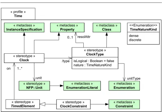
Figure 1 presents a simplified view of MARTETime subprofile. The green elements are defined outside the profile itself but are useful to understand the profile. The
stereo-type ClockType extends the metaclass Class. It models classes of compatible clocks,
i.e., clocks of the same nature (discrete or dense) and that use the same set of units. The stereotypeClock extends metaclasses InstanceSpecification and Property. It models a set of instants as defined in the previous subsection. Clocks can appear either in instance diagrams to represent a snapshot of a system at a given time or in composite structure diagrams to represent a family of possible behaviors. Starting from there, several identified model elements can be associated with one or several clocks using one the concrete stereotype that specializes the abstract stereotypeTimedElement. This association with a clock gives the ability to the model element to embedd expressions or value specifications identifying precisely instants or durations. Having different ref-erence clocks is very useful in distributed systems where different elements use different time bases. It is also useful in electronic design with manycore architectures or even monocore where several time domains are defined (main clock, bus clock. . . ). Locally, it is often better to consider these time domains/bases (clocks) as independent so each part can be designed separately. However, when integrating it is required to under-stand the relations between these clocks to deal with inter-domain communications. Clock constraints have been defined with that objective. They make explicit relations amongst clocks. The stereotype ClockConstraint extends the metaclass Constraint and the Clock Constraint Specification Language (CCSL) gives a possible non-normative concrete syntax to specify constraints.CCSLis briefly introduced in the next section.
3 Clock Constraints
The Time structure defines relations between instants. However, a clock being an infi-nite set of instants it is neither realistic nor practical to specify constraints one by one. Based on instant constraints, it is easy to build more powerful relations that define infinitely many instant relations. We call these relations clock constraints. We can clas-sify clock constraints into three families: coincident-based, precedence-based and mixed constraints.
3.1 Coincidence-based constraints
The coincidence-based clock constraints defines infinitely many coincidence instant relations. Most of the time, this kind of constraint defines a subclock from a given superclock, i.e., a clock less frequent. For instance we can select every third instant to create a periodic subclock of period 3. But as most clock constraints are relations, as opposed to functions, they can also do the contrary and define a superclock from one (or a set of) subclock(s). For example, to model a phase-lock loop (PLL) system, one may wish to oversample four times a given clock. The most frequently used constraint
4 « profile » Time « metaclass » Class « stereotype »
Clock isLogical : Boolean = false nature : TimeNatureKind « stereotype » ClockType 0..1 resolAttr « metaclass » Enumeration unitType « stereotype » NFP::Unit unit « metaclass » InstanceSpecification « metaclass » EnumerationLiteral /type « metaclass » Property 92 mm 42 mm 50 mm 44 mm « stereotype » TimedElement on 1..* « stereotype » ClockConstraint « metaclass » Constraint dense discrete <<Enumeration>> TimeNatureKind
Fig. 1 Excerpt of MARTE Time subprofile
Fig. 2 A isPeriodicOn B period=3 offset=5
of this family is isPeriodicOnwhose semantics is given in a mathematical declarative way by Eq. 1.
A isPeriodicOn B period =P offset =δ
⇐⇒ (1)
(∀k ∈ N?)(A[k] ≡ B[(k − 1) ∗ P + δ + 1])
Figure 2 illustrates this relation with a period of 3 and an offset of 5. This family describes synchronous relations inspired from operators defined in synchronous lan-guages [3].
3.2 Precedence-based constraints
The precedence-based clock constraints define infinitely many precedence instant rela-tions. They characterized asynchronous relarela-tions. The most frequently used constraint of this family isalternatesWith. The relationalternatesWithrepresents alternation between two clocks. A ∼ B means that each occurrence of A is followed by an occurrence of
5
B before any other occurrences of A. The weak form of this relation allows the ith occurrence of B to be simultaneous (coincident) with the ithoccurrence of A, whereas the strict form requires A and B to be disjoint.
Typically, an asynchronous communication implies an alternation between sending and receiving. Let A be the sender and B the receiver. The data is received after having been sent. No other communication can start before the previous one completes. The weak form allows the sender to receive data simultaneously with the emission, but do not force the synchronization. The strict form is used to forbid instantaneous commu-nications. The semantics of the strict form is given by Eq. 2 whereas the semantics of the weak form is given by Eq. 3.
A strictly alternatesWith B ⇐⇒ (2) (∀k ∈ N?)(A[k] ≺ B[k] ≺ A[k + 1]) A alternatesWith B ⇐⇒ (3) (∀k ∈ N?)(A[k] 4 B[k] ≺ A[k + 1]) 3.3 Mixed constraints
Mixed constraints combine both precedence and coincidence relations. There are useful when modeling communications from an asynchronous part of a design to a synchronous part. The most frequently used constraint of this family issampledOn. The relation
sam-pledOnrepresents sampling, it can be used to model time-triggered communications or
for synchronizing asynchronous inputs. A = B C defines a subclock of C that occurs only after an occurrence of B. The strict form of sampledOndoes not instantaneously sample an occurrence of B when it is synchronous with an occurrence of C. In that case, the sampling is postponed.
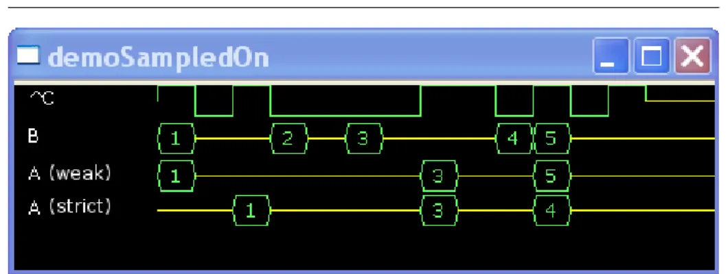
Figure 3 shows one possible scenario involving the clock relation sampledOn with both forms weak and strict. Signal B counts its occurrences and signal A contains the value actually sampled from B.
With both forms the first sample has the value 1. However, with the weak form the first sample occurs on the first occurrence of C whereas it occurs on the second occurrence of C with the strict form. The second sample has the value 3 and the input 2 has been lost in both cases. The third sample occurs at the same time, whatever the form, but does not carry the same value in both cases. The semantics of the strict form is given by Eq. 4 whereas the semantics of the weak form is given by Eq. 5.
A = B strictly sampledOn C
⇐⇒ (4)
(∀a ∈ N?)(∃b, c ∈ N?) ((A[a] ≡ C[c]) ∧ (C[c − 1] 4 B[b] ≺ C[c]))
6
Fig. 3 A=B sampledOn C
A = B sampledOn C (A = B C )
⇐⇒ (5)
(∀a ∈ N?)(∃b, c ∈ N?) ((A[a] ≡ C[c]) ∧ (C[c − 1] ≺ B[b] 4 C[c]))
4 Applying Constraints to UML models 4.1 Using UML constraints
To apply these constraints, one must first create clocks and therefore clock types. Some very useful clock types are provided inMARTE library, likeIdealClockthat represents a perfect dense chronometric clock. Other clocks, with flaws like jitter, drift, can be derived fromIdealClockor rather from one of its instances (a clock). The clockidealClk
is also provided in MARTE library and is an instance of IdealClock. idealClk can be discretized with a given resolution to build, for instance, a chronometric discrete clock whose frequency is 100Hz (see Eq. 6).
c100= idealClk discretizedBy 0.01 (6)
More generally, MARTE also provides a support to use logical clocks, i.e., clocks not directly related to the physical time. Anything that has to be compared (before, after or simultaneous) to something else can be considered as a logical clock. For instance, to give timing information about thread dispatch, a classThreadcan be defined and the stereotype ClockType can be applied to it. Doing so, instances of Thread or properties/parts/ports of typeThreadmay become clocks. Note that, being aClockType
does not prevent from being something else, like aSchedulableResource, it only provides for a support to build clock constraints and express causality relations with other clocks.
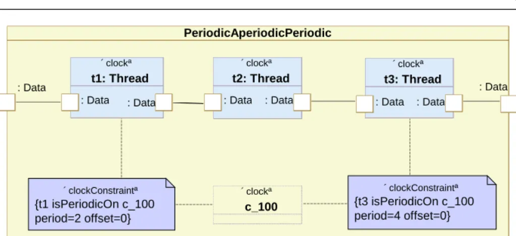
Figure 4 illustrates such a case where two periodic threads (t1, t3) are mixed with an aperiodic thread (t2). The two clock constraints make the two threads (clocks) periodic relative to clock c100. The two threads are harmonic since they refer to the same clock with an offset 0 and the ratio of their period is an integer. Thread t2 is
7 PeriodicAperiodicPeriodic «clock» t1: Thread : Data : Data «clock» t2: Thread : Data : Data «clock» t3: Thread : Data : Data «clock» c_100 «clockConstraint» {t1 isPeriodicOn c_100 period=2 offset=0} «clockConstraint» {t3 isPeriodicOn c_100 period=4 offset=0} : Data : Data
Fig. 4 Periodic threads with CCSL
aperiodic, no relation relates it to a clock. Clock clk is a shared clock (for instance, a chronometric discrete clock) and as such appears within a dashed rectangle. clkis not owned by the classPeriodicAperiodicPeriodicand could be used in another composite structure diagram.
However, a more obvious visual notation may be more appropriate. In particular, constraints are visually explicit when all the constrained elements appear on the same diagram. One purpose of the Time model is to bring consistency between different dia-grams through clocks. Different model elements from different diadia-grams are connected together by clock constraints, which constrain them to behave in a consistent way. The two following subsections propose alternative notations where all clocks are shown on the same diagram.
4.2 Using a CCSL-specific profile
UMLprofile are a way to introduce new concepts but also to change the visual notation. Introducing a new visual language for clock constraints withinMARTEis not practical because MARTE is very big and there are some many other matters to address. A solution can be to define aside, aCCSL-specific profile. Each often usedCCSLconstraint can have its own stereotype associated with a specific icon. The most appropriate meta-class to representCCSLconstraint is probably the metaclassDependency.
Figure 5 shows a possible profile that could be defined to ease the use of CCSL
constraints. The left-hand side part of the figure shows the actual profile. The right-hand side part of the figure shows another composite structure diagram about the same three-thread example. In this example, the diagram represents three new clocks (step1, step2 and step3) that are the actual behaviors (subprograms) executed by the threads. These clocks could also have been shown on the previous diagram but this would have resulted in a very heavy construct. Using the defined stereotypes and their icons brings simplicity even though the semantics is exactly the same.
The relationalternatesWithfrom the threads to their assigned subprogram denotes that every time the thread is dispatched, the subprogram must execute. Additionnally, the subprogram cannot be executed another time before the completion of the previous execution.
8 period : Integer offset : Integer « stereotype » IsPeriodicOn « metaclass » Dependency « profile » CCSL trigger : Clock « stereotype » SampledOn « stereotype » AlternatesWith
↯
PeriodicAperiodicPeriodic « clock » c_100 « clock » t1 : Thread « clock » t2 : Thread « clock » t3 : Thread « clock » step1 : « clock » step3 : « clock » step2 : PeriodicAperiodicPeriodic « clock » c_100 « clock » t1 : Thread « clock » t2 : Thread « clock » t3 : Thread « ClockConstraint » t3 isPeriodicOn c_100 period=4 offset=0 « ClockConstraint » t3 isPeriodicOn c_100 period=4 offset=0 « clock » step1 : « ClockConstraint » t1 alternatesWith step1 « clock » step3 : « clock » step2 : « ClockConstraint » t3 alternatesWith step3 « isPeriodicOn » {period=2, offset=0} « isPeriodicOn » {period=4, offset=0} « alternatesWith » « alternatesWith » « alternatesWith »« alternatesWith » « sampledOn » {trigger=t3}
↯
« ccsl » Three-Thread Example « apply »Fig. 5 Using a CCSL-specific profile
From step1 to step2, there is also a relation alternatesWithsince there is an
asyn-chronous communication. Whenever step1completes, step2takes its output data and executes.
Finally, the ternary relation involvingstep2,step3andt3denotes the synchronization
of step2 output according to the clockt3. Every time t3is dispatched, whatever the
current status of step2output, the data available is sampled andstep3executes using this sample. Obviously, this may lead to data loss, if the sampling rate is too low or to the use of the sample data in multiple executions of step3 if the sampling rate is too high.
This representation requires to define a new profile aside MARTE. In this profile, eachCCSLconstraint has its own stereotype and its properties are determined according toCCSLgrammar. An alternative to the creation of another profile is to use parametric diagrams as described in the following subsection.
4.3 Using SysML parametric diagrams
The UML profile for System Engineering (SysML) [8] is an adopted OMG Specifica-tion to be used at the system level. They have selected a subset of UML constructs calledUML4SysMLand they provide few new extensions amongst whichRefinementand
Parametric diagrams. The former helps making explicit system-level requirements and
tracing their proposed implementations. The latter should be used to represent non-causal relations among values of the system and possibly making explicit within the model, physical laws required for the design.
So, we can use this SysML construct to represent laws related to time, whether physical or logical.SysMLrecommends building a new “Constraint Block” for each new law and then use it in so-called parametric diagrams to apply this law to relevant design values. In our case, we have a small number of identified relations among logical clocks. Consequently, we can easily construct a library ofCCSL-specific constraint block.
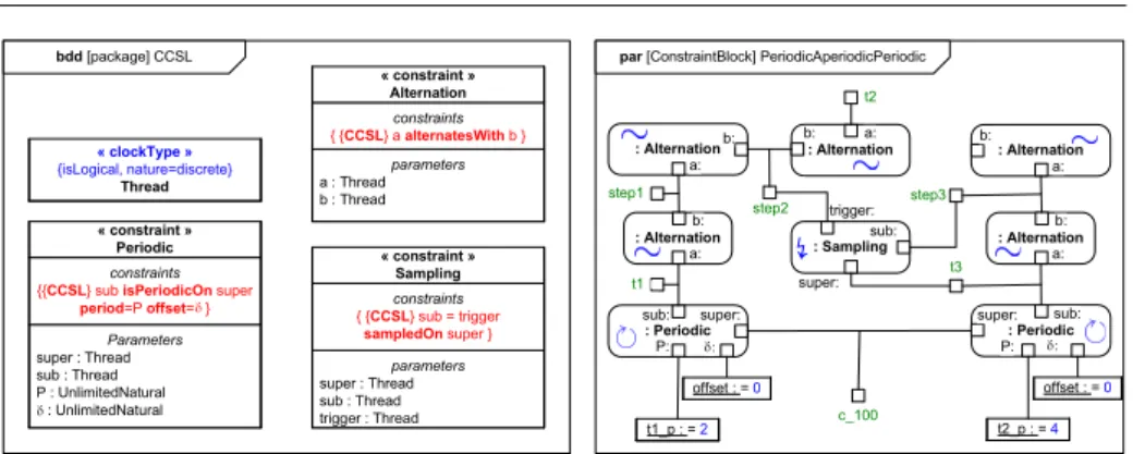
Figure 6 illustrates the same example usingSysMLconstraint blocks and parametric diagrams.
The left-hand side part is an excerpt of the library. Three constraint blocks (Periodic,
Alternation,Sampling) have been defined for each of the threeCCSLrelations introduced
9
par [ConstraintBlock] PeriodicAperiodicPeriodic
« clockType » {isLogical, nature=discrete} Thread Parameters super : Thread sub : Thread P : UnlimitedNatural : UnlimitedNatural constraints
{{CCSL} sub isPeriodicOn super period=P offset= } « constraint » Periodic parameters super : Thread sub : Thread trigger : Thread constraints { {CCSL} sub = trigger sampledOn super } « constraint » Sampling parameters a : Thread b : Thread constraints { {CCSL} a alternatesWith b } « constraint » Alternation bdd [package] CCSL : Periodic sub: t1_p : = 2 P: offset : = 0 super: c_100 : Periodic sub: t2_p : = 4 P: offset : = 0 super: : Alternation a: b: t1 : Alternation a: b: step1 : Alternation a: b: t3 : Alternation a: b: step3 : Sampling sub: super: trigger: : Alternation a: b: t2 step2
↯
Fig. 6 Using SysML parametric diagrams
parameters contains typed formal parameters. The upper compartment, called con-straints, contains the constraint itself that applies on the parameters. In our case, the constraint is defined inCCSL. However, this library is built once and for all, so end-users need not being entirely familiar with the concrete syntax and only need to be familiar with underlying concepts.
The right-hand side part presents the three-thread example as aSysMLparametric diagram. In such a diagram, boxes are properties extracted from the model. Some of the properties are clocks (t1, step1 . . . ), some others have integer values (of f set, t1 p . . . ). These properties may come from different diagrams and different blocks. The rounded rectangles are usages of constraint blocks. Their ports, which represent parameters, are connected with properties using non-causal connectors. Being non-causal means that there is no input or output, whichever value is known causes the other to update. For instance, consideringAlternation, if b is known, one can deduce (partially) a but if a is known, then one can deduce (partially) b.
5 conclusion
The paper has presented some of the clock constraint relations introduced byMARTE
Time model together with their formal semantics. These clock constraints brings con-sistency in the timing information of UMLmodels. Introducing formal models inUML
models is a problem.OMGSpecifications are usually big and are not the right place to put formal specification. Leaving the formal semantics outside the specification leaves the interpretation to tools, possibly having different interpretations in different tools.
WithCCSL, we relyUMLconstraints. However, constraints are not the best visual representation. We propose here two visual alternative notations that result in more compact diagrams. These two solutions are not specific to CCSL and could be easily extended to other constraint-based languages like OCL. The limitation comes from finding the right icon or shape that makes immediately the link with the constraint. Our first proposition implies the creation of a CCSL-specific profile. The second one relies on SysML parametric diagrams. It is interesting to see that all the proposed notations are composite structure diagrams or derived notations.
These two notations attempts to replaceCCSL concrete syntax by a visual repre-sentation and to allow a reprerepre-sentation of otherwise scattered timing information in a single diagram.
10
The next step is to provide analysis support for such diagrams. We already have implemented an Eclipse-based simulator forCCSLconstraints [1] and we are trying to integrate it with parametric diagram to get a direct visual feedback of a simulation run. We have also made some progress to transformCCSLconstraints into other formalisms, like Signal or Petri nets, that have their own analysis techniques and tools [5].
Acknowledgements Some UML diagrams have been built using Papyrus, an open-source tool available at http://www.papyrusuml.org.
References
1. Andr´e, C., Mallet, F.: Clock constraints in UML/MARTE. Research Report 6540, INRIA
(2008). URL http://hal.inria.fr/inria-00280941/en/
2. Andr´e, C., Mallet, F., de Simone, R.: Modeling time(s). In: G. Engels, B. Opdyke, D.C.
Schmidt, F. Weil (eds.) MoDELS, Lecture Notes in Computer Science, vol. 4735, pp. 559– 573. Springer (2007)
3. Benveniste, Caspi, Edwards, Halbwachs, Guernic, L., de Simone: The synchronous lan-guages twelve years later. Proceedings of the IEEE 91(1) (2003)
4. Lee, E.A., Sangiovanni-Vincentelli, A.L.: A framework for comparing models of computa-tion. IEEE Transactions on Computer-Aided Design of Integrated Circuits and Systems 17(12), 1217–1229 (1998)
5. Mallet, F., Andr´e, C.: UML/MARTE CCSL, signal and petri nets. Research Report 6545,
INRIA (2008). URL https://hal.inria.fr/inria-00283077
6. Object Management Group: Unified Modeling Language, Superstructure (2007). Version 2.1.2 formal/2007-11-02
7. Object Management Group: UML Profile for MARTE, beta 2 (2008). OMG document number: ptc/08-07-09
8. OMG: Systems Modeling Language (SysML) Specification 1.1 (2008). OMG document