Publisher’s version / Version de l'éditeur:
Noise Control, 3, 2, pp. 37-39, 86, 1957-02-01
READ THESE TERMS AND CONDITIONS CAREFULLY BEFORE USING THIS WEBSITE.
https://nrc-publications.canada.ca/eng/copyright
Vous avez des questions? Nous pouvons vous aider. Pour communiquer directement avec un auteur, consultez la
première page de la revue dans laquelle son article a été publié afin de trouver ses coordonnées. Si vous n’arrivez pas à les repérer, communiquez avec nous à PublicationsArchive-ArchivesPublications@nrc-cnrc.gc.ca.
Questions? Contact the NRC Publications Archive team at
PublicationsArchive-ArchivesPublications@nrc-cnrc.gc.ca. If you wish to email the authors directly, please see the first page of the publication for their contact information.
NRC Publications Archive
Archives des publications du CNRC
This publication could be one of several versions: author’s original, accepted manuscript or the publisher’s version. / La version de cette publication peut être l’une des suivantes : la version prépublication de l’auteur, la version acceptée du manuscrit ou la version de l’éditeur.
Access and use of this website and the material on it are subject to the Terms and Conditions set forth at
The acoustical design of enclosures for power transformers
Northwood, T. D.; Smith, L. B.; Stevens, E. J.
https://publications-cnrc.canada.ca/fra/droits
L’accès à ce site Web et l’utilisation de son contenu sont assujettis aux conditions présentées dans le site LISEZ CES CONDITIONS ATTENTIVEMENT AVANT D’UTILISER CE SITE WEB.
NRC Publications Record / Notice d'Archives des publications de CNRC:
https://nrc-publications.canada.ca/eng/view/object/?id=18fb6062-fafc-4ac1-bb1a-bc767db5d09a https://publications-cnrc.canada.ca/fra/voir/objet/?id=18fb6062-fafc-4ac1-bb1a-bc767db5d09aSer
TH1
N21r2no.
31 N A T I O N A L R E S E A R C H C O U N C I L c . 2 C A N A D ABLDG
"ak.
"-"&
THE ACOUSTICAL DESIGN OF
ENCLOSURES FOR POWER
TRANSFORMERS
by
T. D. NORTHWOOD, L. B. SMITH AND E.
J .
STEVENSREPRINTED FROM NOISE CONTROL VOL. 3, NO. 2, MARCH 1957
RESEARCH PAPER NO. 31 OF THE
DIVISION OF BUILDING RESEARCH
O t t a w a
HIS publication is being clistributecl by the Division of Building TResearcll of the National Research Council as a contribution to~\.arcIs better builtling in Canada. I t should not be reproduced in whole or ill part, nithout permission of the original publisher.
>
l h e Ilivision .cvoulcl be glad to be of assistance in obtaining such perinission.
Publications ol the Division of Building Research may be ob- tained by illailing the appropriale remit~ance, (a Bank, Express, or Post Office TvIoncy Ordcr or a chcquc nlade payable at par i n Ottawa, to the Receiver Gcncral of Canada, credit National Research Council)
LO the National Research Council, Otta~va. Stamps are not acceptable.
A coupon system has been introduced to make payments for publica~ions relatively simple. Coupons are available in denomina- tions ol 5 , 25, and ,50 cents, and may be obtained by making a re- mi~tance a5 intlica~ctl abovc. ?'hcse coupons may be used for the purcl~ase ol all National Research Council publications including specifications ol' the Canadian Government Specifications Board.
, a e q 5 ? - I - - -
The Acoustical Design
:iah3q-
.
-'.Q
of Enclosures
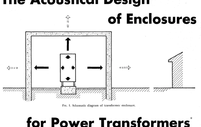
FIG. 1. Schematic diagram of transformer enclosure.
for Power Transformers'
T. D. NORTHWOOD, L. B. SM1TH.t AND E.
I.
STEVENS velopments in magnetic materials.NATIONAL RESEARCI-I C O U N C l L O F CANADA
T h i s paper clisczlsses t h e clesign of enclosures for controlling t h e
noise \?-om large pozuer trc~nsformers. T h e clesign of ventilating
clz~cts and ~eso?la77t
a b s o ~ b e ~ s
for lining enclosz~res is described.
T
KANSFOKMEK noise is not a new problem. T h e litera- ture goes back about thirty years, ancl the history o[ con~plaints prob- ably began with the first trans- former substation. During these years power companies have usu- ally managed to placate the neigh- bors by various means. I n the last ten years, however, several factors*
An address before the seventh annual National Noise Abatement Symposiu~n in Chicago, October 11, 1956.t
NOW with Canadair Limited.have combined to make the prob- lem much more cliffic~ilt. One such [actor is the postwar increase in the use o[ electric power, requiring new substations and a doubling o r tripling of the capacities of sub- stations that formerly were on the borderline of being too noisy. T h e transforincr manufacturers now have an awakened interest in the problem because noise has become the limiting factor in transformer design, preventing them from tak- ing full advantage of recent de-
'The most important factor of all, perhaps, is the fact that people are acquiring the idea that obnoxious noise can ancl should be elimi- nated.
T h e early work in the field was done mainly by power companies and consisted ol experiments with partial or full enclosures, resilient mountings, and other methods of confining noise and vibration. More recently the transformer inanufacturers have been attempt- ing, with some success, to reduce noise at thc source. Eventually the latter studies may substantially re- duce the problenl for new equip- ment, but there are many noisy transformers already in service .rvhose noise must be dealt with by external means. This paper de- scribes some developments toward this end undertaken by the Divi- sion of Building Research in col- laboration with the Hydro-Electric Pourer Commission of Ontario.
We inight begin with a brief sur-
FIG. 2. Sound absorption oS two low- frequency absorbers. Curve A-absorption of 2 f t X 4 ft X 1/4-in. ply\vood and glass- fiber backing. Curve B-absorption of 8 X 8 x 16-in. cinder blocks, one 3/8-in. per- loration per cell.
FIG. 3. Diagram of Helmholtz Resona- tor; s is the cross-sectional area of the hole \vhosc clianleter is cl.
vey of the mail1 features of trans- former noise. T h e problem arises because lor efficient power distri- bution it is necessary to space trans- former stations throughout a com- munity, including residential areas. T h e nearby residents are never very pleased to have one of these installations i n their midst, even when it is hidden behind a res- idential-looking facade. T h e noise is frequently the "last straw."
T h e noise consists mainly of the hum produced by a magnktostric- tion eITect in the iron laininations of the transformer. \i transformer operating at a line frequency of 60 cycles per second produces a funda- mental h u m frequency of 120 cps and a series of harmonics a t 240, 360. a n d so on. T h e fundamental is generally he loudest component, but the first two or three harmonics mav also be iinl~ortant. T h u s , it is mainly a lou-frequency noise. I t happens that lo~v-frequency noises are partici~larly difficult to deal with: the conventional procedures for absorbing or confining or di- recting sound tend to become in- efficient at low frequencies. B u t the noise has the additional feature that it consists of a snlall nuinber of discrete Ircquencies. I n fact, the problem is solved if one can dis- pose of the components at 120, 240, and 360 cps, usually in that order of importance.
T h e r e is often difficulty i n clecid. ing ~vllat is a n acceptable noise level. T h e dccision is complicated by various legal, economic, a n d psy- chological f a c ~ o r s ~ \ ~ h i c h will not be discussed in this paper. Com- inon practice is to ensure that a transformer does not measurably FIG. 4. Horizontal section of transformer
enclosure ventilator stack.
RESONATORS
n
2 4 0 C/S RESONATOR
--.I
increase the ambient level- i n the vicinity ol the nearest neighbor. T h e ambient level may be quite l o ~ v i n the quiet hours just bclore dawn, and this is also the period \vhen noise, interfering with sleep, is particularly objection:tble. Since this problenl is concerned ~ v i ~ l i rel- atively l o ~ v sound levels, it is nec- essary to take account of the low- frequency character of transformer noise coinparetl wit11 most other ambient noises. I11 the past it has been usual in transloriner noise studies to use n.eig11ting network "A" o n the sound-level meter, which gives an approximation to loudness levels for noises in the vicinity of 40 decibels.
Consider, then, the design of a n enclosure that will reduce the noise from a given transformer to a given level a t the nearest neighboring house. Figure 1 illustrates the vari- ous factors which illust be consid- ered. I n addition LO t h e dilect radi-
ation of airborne noise. the trans- former produces vibration ~'vhich may be communicated to the ground and later reradiated as
-
noise i n an adjacent building un- less prevented by suitable vibration isolators. This involves a considera- tion of the mountings, the support- ing slab, and the soil. T h e objec- tiie is to produce the greatest pos- sible impedance nlislnatch between the transformer and t h e soil. T h e vibration problem will bc discussed in a forthcoining paper by A. T. Edwards; ,3 in the present paper
we will concentrate o n airborne noise.
Submitted for presentation at [he
AIEE winter general mecting in New York, J a ~ ~ u a r y 1957.
FIG. 5. Sound atte~irtation in transformer enclosure v e ~ ~ t i l a t o r stack of Fig. 4.
T h e airborne noise from the translormer mav either be ab- sorbed within the ellclosure o r transmitted through the walls. I t is worth noting that i l none o l the s o u n d were absorbccl, the level ~ v o u l d build u p inside the enclo- sure until the soullcl .~voulcl all be translnittecl just as if the enclosure were not there. Hence, tlie result- a n t level outside depends o n both the absorption inside the enclosure a n d thc ;ransmission loss through the walls. A n econolnical design in- volves the judicious consideration of both parameters. Since trans- lormers dissipate a substantial amoullt o l heat, a n enclosure de- sign is usually complicated by ven- tilation reauirements. T h e s e con- stitute a third acoustical problem. T l i e ~ v a l l transrnissioll problem is generally taken care of by local building by1au.s. I l any kind of e n c l o s ~ ~ ~ e is built, most byla~vs re- q u i r e something of the o r d e r o l a 13-in. masonry wall, a n d this is a b o u t as far as o n e wants to go from tlie point of view of sound transmission. Even a t this point very careful design oE doors a n d o t h e r details is r h u i r e c l to realize the lull value of a 13-in. avall.
T h e absorption of lo.cv-lreq~~ency sound is best acliie.i~cc1 by means of a resonant svstcm t ~ ~ n e t l to the re- q ~ ~ i r e c l frequency range. O n e ap- ~ x o a c l i is to tune sharply to the individual f r e q ~ ~ c n c i c s : 120, 240, a n d 360 cps, Cor example. ;2nother is to use broatlly t111icc1 elements that are moclcratcly efficient over the ~\lliole range. T h e latter ap- proach has b e c ~ i f o u n d p;lrticularly ~ ~ s e f u l in tlie clesigli o l absorbent linings for enclosures.
Several resollalit systems might be considered. For example, a thin panel clamped only a t the edges niay have suitable low-£re- quency resonance properties. Suit- able clamping lnay be obtaincd by filling the back space. T h e absorp- tion properties o l one such panel are s l ~ o ~ v n in Fig. 2 (Curve A).
t\nother uselul system is tlie I Ielmholtz Resonator, illustrated in Fig. 3. T h e resistive elelllent in ~ l ~ i s system may be provided by a I1o.i~-resistant material i n the ori- lice o r in the cavity, o r by porosity in the xualls of t h e cavity. T h e
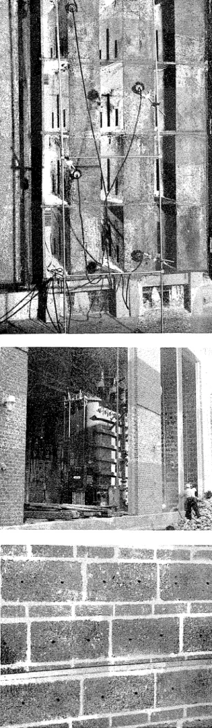
FIG. 6. T e s t array, of ventilator
stack clcments.
FIG. 7. View of transformer enclosure d u r i n g construction.
FIG. 8. Close-up of pcrfol.atec1 block a t ~ s o ~ l ~ i n g wall.
acoustical design is fairly straight- lorward; tlie probleln is mainly to devise a simple, inespcnsive way of constructing the elements. For roofless enclosures there is tlie aclclitional restriction that the ele- ments m ~ ~ s t withstand the effects of weather. Several Helmholtz Res- onator systems were devised to meet these requirements. T h e sim- plest one, suggested by Mr. A. T . Edwards of the O n t a r i o Hydro, was m a d e by drilling a hole of suit- able size into each cavity of a n or- dinary hollow cinder block. T l i e absorption properties of this systcm are sho~t711 i n Fig.
2
(Curve B). Sim- ilar results were obtained with building blocks lnade of other~ O ~ O L I S aggregates such as ex-
p a n d e d slag a n d expanded mica. I n all cases good absorptioll was obtaincd over a t least two octaves. 111 order to achievc maximum sound absorption it is necessary to Ixevent c o r n m ~ ~ n i c a t i o n between cells over more t h a n 2 or 3 ft. O n e Tvay to accomplish tliis is to use a course of brick o r solid blocks lor every three o r l o u r courses of resonator blocks. An example oE tliis construction is slio~vn in Fig. 8. T l i c holes could possibly be lormed by a modification o f tlie sta~idarcl block-making process, b u t it costs only a few cents to drill them. For next: construction t h e perforated blocks form the i n n e r p a r t o l a standard wall. T h u s , thc acoustical treatment for the enclo- sure may be o b t a i n e d lor the cost o f drilling the holes: a Cexs cents per square loot.
T u r n i n g now to tlie matter o f ventilation, the lo~tr-lrequency char- acteristic of the noise again presents a problem. Conventional noise-at- t e n ~ i a t i n g stacks that provide atten- atio ions of the order of 20 clb at 120 cps a r e large a n d costly. Again t h e
( C o n t i n u e d o n page S 6 )
Enclosures for Power Transformers
Helmholtz Resonator principle is a useful solution. One might use something like the perforated cin- der blocks, broadly tuned to be absorbent over the range of fre- quencies. One can do better, how- ever, by concentrating on the dis- crete frequencies and by locating each tuned element strategically in the length of the duct. Figure 4 illustrates some preliminary experi- ments with a very short duct de- signed to attenuate 120 and 240 cps. T h e duct is about a quarter- wavelength long at 120 cps. A sim- ple duct of this length provides some attenuation bv virtue of the impedance inisinatch at the two ends. An attenuation of about 10 db was obtained for a simple duct of this type. T h e attenuaiion was z 1 increased to the design value of 20 db by introcluci~lg 120-cps ab- sorbers near the two ends. T h e 240-cps component falls in a trans- mission band for a simple duct of this length, but a 210-cps absorber at the mid-point attenuates this fre-
quency most effectively. Results ob- tained with a n array of these units are shon~n in Fig. 5 . Figure G sholvs the array under test. I t is envisaged that a n assenlbly of these units would be ii~corporatecl in the lower ,,art of enclosire walls to form an air inlet. I n sinall stations a roof might not be needed. Otherwise, a similar outlet stack at roof height coulcl be used. Experiinents aimed at obtaining slightly higher atten- uation are currently under way with variants of this design.
-
Another approach to the venti- lation problem is to separate the cooling coils froin the transformer U aild enclose only the transformer. Figure
7
shows such a station now under constructioi~. T h e station is lined wit11 ~ e r f o r a t e d blocks of the type described earlier, a close-up of ~rllich is sl~own in Fig. 8. T w o33 000-kva transforiners are being installed now, with provision for a third at a later date. T h e large openings, required only for install- ing transformers, will be blocked off wit11 preformed concrete slabs. A feu? ineasureinents have been inacle on the unfinished station, ailcl present iiidications are that the
noise levels will be comfortably be- low the design values.
This paper is inte~ldecl not so much as a solution to the trans- former noise problem as an illustra- tion of the special techniques that
.
are useful in dealing with noises of this special class. Transforlller noise is perhaps the best exam- ple, but there are other noises of this type, consisting mainly of a iew low-frequency components, in which the fruitful line of attack is to consider one frequency at a time.No attempt has been nlade here to cover the whole field of trans- former noise research. For readers of NOISE CONTROL it shoulcl suf- fice to draw attention to several re- cent papers in that magazine. Par- ticular reference should be made, though, to the excellent bibliogra- phy o n transformer noise sponsored by the AIEE and reprinted in the November 1955 issue of NOISE CONTROL.
This paper is a contribution from the Division of Building Re- search, National Research Council of Canada and is published with the approval of the Director.
A list of publications issued by the Division of Building Research can be obtained on application to the Publications Section, Division of Building Research, National Research Council, Ottawa, Canada.