Publisher’s version / Version de l'éditeur:
Vous avez des questions? Nous pouvons vous aider. Pour communiquer directement avec un auteur, consultez la première page de la revue dans laquelle son article a été publié afin de trouver ses coordonnées. Si vous n’arrivez pas à les repérer, communiquez avec nous à PublicationsArchive-ArchivesPublications@nrc-cnrc.gc.ca.
Questions? Contact the NRC Publications Archive team at
PublicationsArchive-ArchivesPublications@nrc-cnrc.gc.ca. If you wish to email the authors directly, please see the first page of the publication for their contact information.
https://publications-cnrc.canada.ca/fra/droits
L’accès à ce site Web et l’utilisation de son contenu sont assujettis aux conditions présentées dans le site LISEZ CES CONDITIONS ATTENTIVEMENT AVANT D’UTILISER CE SITE WEB.
Proceedings of the 23rd IAHR International Symposium on Ice, 2016-06
READ THESE TERMS AND CONDITIONS CAREFULLY BEFORE USING THIS WEBSITE.
https://nrc-publications.canada.ca/eng/copyright
NRC Publications Archive Record / Notice des Archives des publications du CNRC :
https://nrc-publications.canada.ca/eng/view/object/?id=3fa8c9b6-8328-419b-9d19-b931a80b89db https://publications-cnrc.canada.ca/fra/voir/objet/?id=3fa8c9b6-8328-419b-9d19-b931a80b89db
NRC Publications Archive
Archives des publications du CNRC
This publication could be one of several versions: author’s original, accepted manuscript or the publisher’s version. / La version de cette publication peut être l’une des suivantes : la version prépublication de l’auteur, la version acceptée du manuscrit ou la version de l’éditeur.
Access and use of this website and the material on it are subject to the Terms and Conditions set forth at
Phase II lab tests of the Blade Runners Concept for reducing ice-induced vibration of structures
23
rdIAHR International Symposium on Ice
Ann Arbor, Michigan USA, May 31 to June 3, 2016Phase II Lab Tests of the Blade Runners Concept for
Reducing Ice-Induced Vibration of Structures
R. Gagnon
Ocean, Coastal and River Engineering National Research Council of Canada
St. John’s, NL, Canada robert.gagnon@nrc-cnrc.gc.ca
A large suite of tests of the Blade Runners concept for reducing ice-induced vibration of structures was conducted in NRC/OCRE’s Large Cold Room facility using a set of differing ice crushing platens that had a variety of blade arrays on them. These Phase II tests were intended to investigate the factors that influence the performance of the technology and to identify the best performing Blade Runners crushing platens. In general two types of tests were conducted: (a) tests where crushing was from the vertical direction and where the platens were fixed from movement in the horizontal direction and (b) tests where the platens were moved horizontally during the crushing to investigate frictional aspects of the technology. For most cases high-speed imaging was used to observe the ice contact zone, by viewing through the platens that were made of acrylic, as it evolved during the tests. Blade shape, orientation and array spacing were investigated as well as platen material. Vertical crushing rates were in the range 10 – 30 mm/s and the horizontal sliding rates were in the range 4.14 – 30 mm/s. All tests were conducted at -10 oC. Three types of freshwater ice were used and 14 platens with open arrays of blades were tested. Results showed that blade shapes and array spacing were important factors and that square-column and square-pyramid blades performed well. The arithmetic average of the high-roughness profiles for the surfaces of the two best performing platens were 0.075 mm (square pyramids) and 0.375 mm (square columns). Load records from tests using flat bladeless crushing platens exhibited a high-amplitude sawtooth load pattern, resulting from fairly regular ice spalling events, that is typical of ice crushing in the brittle regime. This type of spalling behaviour, and associated sawtooth load pattern, is responsible for ice-induced vibration of structures when ice sheets encroach on them. The high-performance Blade Runners platens significantly reduced the amplitude of the sawtooth load patterns. During tests there was no evidence of entrapment of crushed ice between blades nor was there any evidence of high frictional forces on the platens during tests involving horizontal sliding.
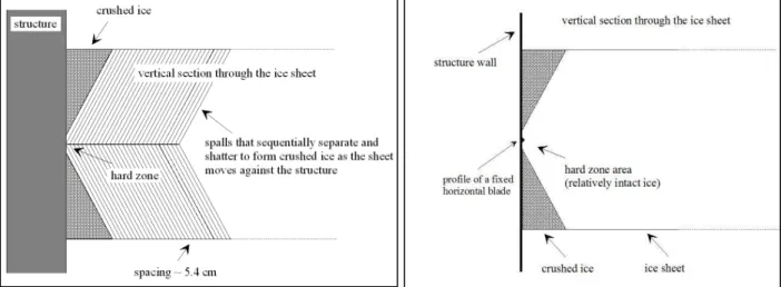
Figure 1. Schematic illustrating the sequence of spalls that will occur as an ice sheet moves to the left and crushes against the Molikpaq-type structure. Regions of relatively soft crushed ice, located above and below a central region of relatively intact hard ice, are also indicated. From Gagnon (2012).
Figure 2. A schematic illustration of a single horizontal blade attached to a wall of a structure at an elevation so that it is inside the hard zone of an ice sheet interacting with the wall. From Gagnon (2014).
.
1. Introduction
Ice crushing induced vibration has been the subject of interest in many investigations ever since problems were first encountered for some offshore structures when ice sheets moved against them. The most widely known and studied events are those associated with the Gulf Canada Resources Ltd. Molikpaq caisson facility that occurred in 1986 during operations at the Amauligak I-65 site in the Canadian Beaufort Sea. Various analytical and numerical approaches have been applied to explain ice crushing induced vibration. Recently new understandings of ice crushing, with emphasis on spalling behavior, have been applied to the problem and when large-scale aspects of the ice are sufficiently taken into account this can explain ice-induced vibrations, including lock-in behaviour (Gagnon, 2012).
2. Concept Description and Multi-Blade Arrays
From the new understandings of the mechanisms that constitute spalling phenomena it should be possible to incorporate small prominences into the design of a structure’s faces that could disrupt or control the ice spalling process. Studies such as the Hobson’s Choice Ice Island tests and small-scale laboratory ice crushing tests have shown that the fractures that create spalls nucleate roughly from the central region of the ice-structure contact zone (Gagnon, 1998, 1999, 2008). In the case of the edge of an ice sheet interacting with a large structure we could envisage, in an idealised and simple case, a line of static horizontally-oriented relatively thin metallic ‘blades’. These blades would punch/run slightly into the hard zone area of the ice contact region (Figures 1 and 2) to initiate/nucleate spall-creating fractures that would mitigate excessive cyclic loading and reduce loads. Note that every spalling event that occurs during ice crushing results in an abrupt reduction of load because a piece of ice breaks away from the intact ice and shatters. Laboratory tests corresponding to this simplified scenario, i.e. using a small-profile single blade that spanned the length of a crushing platen, were conducted in a Phase I test program and the
Figure 3. Photograph of the acrylic platen with the array of small regular square pyramids on its surface (platen dimensions: 166 mm x 129 mm x 25 mm). The pyramids were 1 mm in height and 2 mm wide at the base. The space between each adjacent pyramid was 2 mm. The arithmetic average of the high-roughness profile for the surface of the platen was 0.075 mm.
results demonstrated that the concept significantly reduced high-amplitude cyclic loading (Gagnon, 2014). A key aspect of this technology is that for a blade to be effective it must be positioned in the hard zone region of ice contact. In the Phase I tests the hard zone generally stayed fairly localized in the mid region of the sample thickness, as has been shown in real ice edge crushing experiments (e.g. Frederking, 2004; Määttänen et al., 2011; Sodhi et al., 2001; Takeuchi et al., 1997).
A more realistic scenario would involve two dimensional arrays of blades having suitable dimensions and spacing, that span the full horizontal extents of the structure faces and that have sufficient vertical extent to accommodate tidal and ice thickness variations. The present Phase II study involved testing a variety of lab-scale ice crushing platens with patterned surfaces having differing blade shapes, orientations and array spacings to find the optimum configurations that would mitigate high-amplitude sawtooth load patterns that normally arise from large and regular spalling events. When ice encroaches on a structure there is often a sliding component to the interaction. Therefore the Phase II test program also included tests where a frictional component was included when ice was crushed against the platens with the arrays of blades.
3. Experimental Setup and Results from the Lab Tests
To test the Blade Runners concept for arrays of blades a series of 14 differing crushing platens were fabricated, with the following blade shapes: continuous or segmented horizontal wedges (2 cases: 45o base angle and 27o base angle); continuous or segmented horizontal flat bars; wedged-shaped crosses (45o base angle); truncated cones; square columns and square pyramids. Figure 3 is a photograph of the crushing platen with square pyramids. The pyramids were 1 mm in height and 2 mm wide at the base. The space between adjacent pyramids was 2 mm. The height, base dimensions and spacing for the square columns were the same as that of the square pyramids. We shall see below that these two platens were the best performers in terms of reducing large-amplitude cyclic loading due to spallation. The arithmetic average of the high-roughness profiles for the surfaces of the two platens were 0.075 mm (square pyramids) and 0.375 mm (square columns). Some platens had the same blade shapes but differing spacing. All platens, except one made of Aluminum, were made of acrylic. The ice crushing tests were performed in NRC-OCRE’s Cold Room facility. The strategy was to crush samples of ice against platens with blade arrays and compare those results with those from crushing experiments using a flat platen with no blade array.
A B C D E F G H
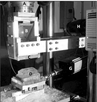
Figure 4. Photograph of the crushing-friction test setup. (A) Vertically-oriented test-frame load cell for measuring the normal load; (B) Mirror; (C) Acrylic crushing-platen; (D) Ice specimen in ice holder; (E) Rail-car assembly; (F) Load cell used to measure the horizontal friction force; (G) Linear actuator used to slide the rail-car and ice sample horizontally; (H) High-speed imaging camera.
Figure 4 shows a photograph of the test setup where the ice, confined in a rigid holder, is pressed in the vertical direction at a fixed rate against a transparent acrylic crushing platen (2.5 cm thickness) in a testing frame. The crushing platen is backed by a secondary polished acrylic support plate (5 cm in thickness). The ice holder is attached to the top face of a 2.5 cm thick metal plate. The plate has four commercial ‘frictionless’ ball-bearing cars attached under it that ride on two metallic rails in the horizontal direction parallel to the long axes of the ice specimen and the crushing platen. For tests involving frictional sliding an electric actuator was used to move the plate and ice holder at controllable fixed rates. High-speed images of the ice-platen contact region were recorded by viewing through both the support plate and the crushing platen by means of a mirror situated between the supporting posts for the plate and platen.
Some ice samples were prepared from freshwater granular ice blocks grown in the lab (grain size ~ 4 mm) and others were prepared from a columnar-grained freshwater ice sheet grown in a basin (column diameter ~ 5 mm). During tests the columnar grains were orthogonal to the vertical crushing direction and the long axis of the ice sample. Each ice sample was approximately 7 cm in height, and 12 cm by 6.5 cm at its base. The top of the samples was given a rounded-wedge shape. Each sample’s base was freeze-bonded to an ice holder consisting of an acrylic plate with a rectangular band of steel (2 cm in height) attached to it that encompassed the base of the ice specimen. The ~ 1 cm gap between the ice sample and the confining steel band was filled with snow and then saturated with water near 0 oC so that, when frozen, it provided confinement at the base of the ice sample to prevent it from shattering during testing. Tests were carried out at –10 oC and the load data from the vertical crushing actuator and the lateral sliding actuator were acquired at 6144 samples per second. The vertical crushing rates used for these tests were 10, 20 and 30 mm/s. The horizontal sliding rates used were 4.14, 10, 12.42 and 20 and 30 mm/s. All ice samples were crushed to a depth of ~ 35 mm.
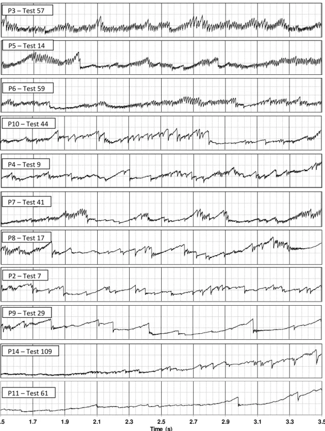
Figure 5 shows the major central portions of load records for a variety of the platens tested. The load records are arranged from top to bottom in the order of the effectiveness of the platen at mitigating the sawtooth load pattern, where the best performing platens (square columns and square pyramids) are at the bottom. It was clear early in the test program that blade spacing was
P3 - Test_57 P5 - Test_14 P6 - Test_59 P10 - Test_44 P4 - Test_9 P7 - Test_41 P8 - Test_17 P2 - Test_7 P9 - Test_29 P14 - Test_109 1.5 1.7 1.9 2.1 2.3 2.5 2.7 2.9 3.1 3.3 3.5 Time (s) P11 - Test_61 P3 – Test 57 P10 – Test 44 P6 – Test 59 P5 – Test 14 P2 – Test 7 P8 – Test 17 P7 – Test 41 P4 – Test 9 P11 – Test 61 P14 – Test 109 P9 – Test 29
Figure 5. Load records from tests using eleven of the crushing platens. The efficacy of the blade shapes, array patterns and spacings to reduce high-amplitude sawtooth load patterns (HASLP) increases from the top record to the bottom record. Platen P11 (at the bottom), that had an array of square columns on its surface, was one of the best performing platens, that is, the record is relatively smooth. The y-axis scale on all the records is 0-30 kN.
0 5000 10000 15000 20000 25000 30000 2.2 2.3 2.4 2.5 2.6 2.7 2.8 L o a d ( N ) Time (s) Test_66: Bladeless Flat Platen
Test_61: Square Columns Platen (P11)
Figure 6. Expanded view of the load records from one of the best performing crushing platens (P11) and from a ‘bladeless’ flat acrylic platen. The prominent sawtooth load pattern is evident in the latter case.
0.00E+00 5.00E+12 1.00E+13 1.50E+13 2.00E+13 2.50E+13 15 35 55 75 95 115 135 155 M a g n it u d e S q u a re d Frequency (Hz) Without Blades With Blades
Figure 7. Magnitude-squared frequency domain plots, obtained from Fourier transforms of the time domain load traces of the bottom plot in Figure 6 and a load trace from a test using a flat ‘bladeless’ platen, showing power amplitudes at respective frequencies. Note that the high amplitude peaks associated with the ‘no blade’ case (flat platen) are substantially reduced in the case with the blades (square columns platen (P11)).
an important factor and that the platens having blade arrays with close spacings were the most efficacious of the ensemble.
Figure 6 shows an expanded portion of the load time series for the cases where blades were present on a platen (platen P11, an effective platen) and when blades were not present (flat acrylic platen). The two records are distinctly different in that there are a large number of sawtooth oscillations of significant amplitude in the record corresponding to the ‘bladeless’ case, whereas the ‘bladed’ case shows relatively few sawtooth oscillations and they have small amplitude. The frequency domain plots of the major central portions of the load records (1.5 s to 3.5 s) are also instructive (Figure 7).
The physical behaviour of the ice during the crushing is responsible for the load record characteristics in both cases. The key thing to note is that an ice spalling event is responsible for the sharp drop in load associated
with any particular load sawtooth. A spalling event generally refers to what happens when a portion of relatively intact ice, a hard zone, rapidly separates from the ice contact region and shatters, leading to a sudden drop in load. The shattered spalls have properties of crushed ice that is capable of supporting low pressure, whereas the remaining hard-zone ice will be relatively intact and is capable of supporting high pressure. In the case where no blades are present the temporal spacing of the load sawteeth is such that there is significant build-up of elastic stress in the ice/apparatus system between spalling events, hence the load sawteeth have high amplitudes. In
2.869 s 2.953 s 2.943 s 2.879 s 2.560 s 2.580 s
Figure 8. Two sets of two images from the high-speed image record of a test using platen P11. The view is through the transparent acrylic crushing platen. The grid of small square columns is apparent. Time stamps are included on the images. A horizontally-elongated dark hard zone that consists of relatively intact ice where the pressure is high is visible in each image. The hard zone is surrounded by crushed ice (the white material). The high-speed digital camera captured images at 500 images/s, however the figure shows two non-sequential pairs of images, at 2.869 s and 2.943 s, where each pair capture a single small spalling event (indicated by arrows). In contrast, the third pair of images is from a test using a flat bladeless crushing platen, where a large (typical) spall event was captured that spanned a significant portion of the whole hard zone (the central dark dendritic region angled towards the upper left). The images in any pair are not sequential. The width of each image is ~133 mm. the case where the ‘blades’ are present
there are still spalling events occurring, and associated load sawteeth, however the frequency of the sawtooth pattern is much higher than in the previous case and there is consequently much less elastic stress build-up in the ice/apparatus system between the events.
Figure 8 shows two sets of two images from the high-speed image record of a test using the crushing platen with the array of square columns, and one pair of images from a test using a flat bladeless crushing platen. The views are through the transparent acrylic crushing platens and the grid of small square columns is apparent in the top two image pairs. The high-speed digital camera captured images at 500 images/s, however the figure shows two non-sequential pairs of images at 2.869 s and 2.943 s for the square columns platen, where each of the two pairs captures a single small spalling event. We see a roughly centrally-located horizontally-elongated dark hard zone that consists of relatively intact ice (Gagnon, 1999) where the pressure is high (~ 30-70 MPa). The relatively intact hard zone appears dark because a thin sheet of black plastic was placed between the actuator head and the ice holder so that the black sheet was visible through the translucent ice sample and ice holder in areas where there was no opaque crushed ice (the white material). The elongated shape of the hard zone is due to the shape of the original ice sample (a horizontal wedge) that
provides confinement governed by its geometry (Spencer and Masterson, 1993). The hard zone is surrounded by white material that consists of low-pressure (0-10 MPa) pulverized spall debris (Gagnon, 1999) that is flowing away from the high-pressure region, generally extruding along the channels between the columns.
The physical behaviours of the ice during the crushing mentioned above are quite evident in the high-speed imaging records of the tests. For bladed platen P11 small spalls intermittently break away from the hard-zone region at various locations along its elongated shape. Fig. 5 shows two of the more distinctive small spalling events (indicated by arrows) that occur over the period of time 2.869 s to 2.953 s. Fig. 5 also shows an image pair from a test using a flat ‘bladeless’ platen where the images capture a single large spalling event that involves a significant portion of the area of the hard zone. The small spalling events in Fig. 5 arise because the square columns act as nucleation sites for fracture and spallation. Hence, the amplitudes of the sawteeth are very small and barely discernible compared to the ‘bladeless’ case. The effect of the blades is to initiate many more, and smaller, spalling events than would have occurred with a bladeless crushing plate. Statistics from the present tests indicated that the average loads over the durations of the tests were roughly the same regardless of the presence or absence of the blades.
Some observations related to the possible entrapment of crushed ice at the platen/ice interface that might degrade the performance of the blades. The high-speed imaging observations of tests indicated there was no entrapment of crushed since the blade arrays have an open structure that provides channels of escape (between the blades) for the crushed ice. As a ‘worst case’ test crushed ice that was left on a platen at the end of one test was kept in place for a test with a new ice specimen. The former crushed ice accumulation was quickly cleared off the platen by the crushing action of the ice sample at the early stage of the new test, that is, the platen performed in the same manner as if the former crushed ice had not been there.
The other main observations relate to the tests that had a frictional sliding component. Most of the crushing friction tests were conducted using the platens that performed the best at reducing high-amplitude sawtooth load patterns (HASLP), that is, the platens with square columns and square pyramids. Some highlight results are: (1) Generally the ability of a platen to reduce HASLP was not strongly influenced if there was a frictional sliding component in the tests. (2) The friction coefficients were surprisingly low given the high degree of roughness of the platen surfaces. Indeed for several tests the coefficients were comparable to or less than coefficients for flat steel plates. (3) The friction coefficients were relatively fixed for constant ratios of sliding speed and the vertical crushing rate. Columnar and granular ice yielded similar results in terms of reduction of HASLP and crushing-friction characteristics.
4. Conclusions
In this second series of tests of the Blade Runners technology it was observed that the multi-blade array concept effectively mitigated large-amplitude sawtooth loading by increasing the spalling rate, and spall size, and consequently reducing the sawtooth load amplitude. Certain platens (e.g. P11, P13, P14) that had either square pyramids or square columns were the best performers due to the shape, spacing and arrangement of the blades on the platen surfaces. Entrapment of crushed ice, and potential degradation of performance, did not occur for any of the platens because they had open arrays of blades. The ice crushing friction coefficients for all of the blade-array platens were extraordinarily low, that is, in the same vicinity as that of flat steel. The friction coefficient was a constant for any particular ratio of vertical crushing rate and sliding rate. Columnar and granular ice yielded similar results in terms of friction characteristics and reduction of HASLP. Assuming that the technology scales appropriately, we can extrapolate to the field case of an ice sheet encroaching from a non-normal direction on a structure face with
blades on it. From the above conclusions we can surmise that frictional forces on the faces of the structure would be no different than not having blades present. Furthermore the frictional forces would be independent of the ice sheet speed.
5. Acknowledgements
I would like to thank Austin Bugden for technical assistance during the test program and analysis of results, and I am grateful to NRC for its support of this work.
6. References
Frederking, R., 2004. Ice Pressure Variations during Indentation. Proc. IAHR Symposium on Ice, St. Petersburg, Russia, pp. 307–314.
Gagnon, R.E., 1998. Analysis of Visual Data from Medium Scale Indentation Experiments at Hobson’s Choice Ice Island. Cold Regions Science and Technology, Vol. 28, 45-58. Gagnon, R.E., 1999. Consistent observations of ice crushing in laboratory tests and field
experiments covering three orders of magnitude in scale. Proc. POAC-99, Helsinki, Finland, 2, pp. 858–869.
Gagnon, R.E., 2008. High-speed imaging of mechanisms responsible for sawtooth cyclic loading during ice crushing. Proceedings of IAHR 2008, Vancouver, Canada, volume 2, pp. 983– 991.
Gagnon, R., 2012. An Explanation for the Molikpaq May 12, 1986 Event. Cold Regions Science and Technology 82 (2012) 75-93.
Gagnon, R., 2014. First Lab Tests of the Blade Runners Concept for Reducing Ice Induced Vibration of Structures. Proceedings of the 22nd International Symposium on Ice, IAHR 2014, Singapore, pp. 282-289.
Määttänen, M., Marjavaara, P., Saarinen, S., 2011. Ice crushing pressure distribution against a compliant stiffened panel. Proc. 21st Int. Conf. On Port and Ocean Engineering under Arctic Conditions, Montreal, Canada, POAC 2011, paper #038.
Sodhi, D.S., Takeuchi, T., Nakazawa, N., Kawamura, S.A.M., 2001. Measurements of ice force and interfacial pressure during medium-scale indentation tests in Japan. Proc. 16th International Conference on Port and Ocean Engineering under Arctic Conditions, Ottawa, Ontario, Canada, pp. 617–626.
Spencer, P.A., Masterson, D.M., 1993. A geometrical model for pressure aspect-ratio effects in ice-structure interaction. Proceedings of OMAE 1993, 4, 113-117, (1993).
Takeuchi, T., Masaki, T., Akagawa, S., Kawamura, M., Nakazawa, N., Terashima, T., Honda, H., Saeki, H., Hirayama, K., 1997. Medium-scale field indentation tests (MSFIT)—ice failure characteristics in ice/structure interactions. Proc. of the 7th Int. Offshore and Polar Engineering Conference, Honolulu, USA, vol. II, pp. 376–382.