READ THESE TERMS AND CONDITIONS CAREFULLY BEFORE USING THIS WEBSITE. https://nrc-publications.canada.ca/eng/copyright
Vous avez des questions? Nous pouvons vous aider. Pour communiquer directement avec un auteur, consultez la première page de la revue dans laquelle son article a été publié afin de trouver ses coordonnées. Si vous n’arrivez pas à les repérer, communiquez avec nous à PublicationsArchive-ArchivesPublications@nrc-cnrc.gc.ca.
Questions? Contact the NRC Publications Archive team at
PublicationsArchive-ArchivesPublications@nrc-cnrc.gc.ca. If you wish to email the authors directly, please see the first page of the publication for their contact information.
NRC Publications Archive
Archives des publications du CNRC
This publication could be one of several versions: author’s original, accepted manuscript or the publisher’s version. / La version de cette publication peut être l’une des suivantes : la version prépublication de l’auteur, la version acceptée du manuscrit ou la version de l’éditeur.
Access and use of this website and the material on it are subject to the Terms and Conditions set forth at
Experimental study and numerical modelling of the fire resistance of
wood-stud wall assemblies
Bénichou, N.; Kodur, V. K. R.; Sultan, M. A.
https://publications-cnrc.canada.ca/fra/droits
L’accès à ce site Web et l’utilisation de son contenu sont assujettis aux conditions présentées dans le site LISEZ CES CONDITIONS ATTENTIVEMENT AVANT D’UTILISER CE SITE WEB.
NRC Publications Record / Notice d'Archives des publications de CNRC:
https://nrc-publications.canada.ca/eng/view/object/?id=8f9112ee-68ca-42eb-9376-eb25351b6a3b https://publications-cnrc.canada.ca/fra/voir/objet/?id=8f9112ee-68ca-42eb-9376-eb25351b6a3b
Experimental study and numerical modelling of the
fire resistance of wood-stud wall assemblies
Bénichou, N.; Kodur, V.R.; Sultan, M.A.
A version of this document is published in / Une version de ce document se trouve dans : 4th Structural Specialty Conference of the Canadian Society for Civil Engineering,
Montreal, Quebec, June 5-8, 2002, pp. 1-10
www.nrc.ca/irc/ircpubs
NRCC-45166
EXPERIMENTAL STUDY AND NUMERICAL MODELLING OF THE FIRE
RESISTANCE OF WOOD-STUD WALL ASSEMBLIES
N. Benichou, V. K. R. Kodur, M. A. Sultan
Institute for Research in Construction, National Research Council Canada, Ottawa, Canada
ABSTRACT: This paper presents the results from an experimental study on the behaviour of gypsum
board protected, wood-stud shear wall assemblies. The experimental study consisted of fire resistance tests on 12 full-scale wall assemblies. The factors investigated included effects of placement and type of shear membrane, insulation type, presence of resilient channels and load intensity on the fire resistance of such assemblies. The test results show that the shear membrane placement and insulation type, significantly influence the fire resistance of wood-stud shear walls. The results of this and other studies were used to develop a model for predicting the fire resistance of wood-stud wall assemblies. The model couples a heat transfer sub-model and a structural sub-model. The heat transfer sub-model predicts the temperature profile inside the wood-stud assembly and the time to insulation failure. The structural sub-model uses the temperature profile to calculate the deflection of the studs and the time to structural failure of the assembly. A comparison with test results indicates that the model predictions are reasonable.
1. INTRODUCTION
As a result of a number of earthquakes and windstorms around the world, there has been an increased focus on the design of buildings to resist lateral movement when exposed to high winds or earthquakes. In the case of wood-frame construction buildings, shear walls are often incorporated into the building design to resist these loads. In multi-family residential buildings, these shear walls form the critical boundaries between compartments and are required to exhibit acceptable fire resistance to contain the fire within the compartment of fire origin. However, there is very limited information on the fire performance of such assemblies in the literature (Kodur and Sultan 2000) and in the National Building Code of Canada (NBCC, NRC 1995). To generate the necessary fire resistance information, a collaborative research project between the National Research Council of Canada (NRC) and industry partners was initiated to determine the fire resistance performance for various types of shear wall assemblies of wood-stud construction. In this paper, the results of an experimental study on the behaviour of 12 load-bearing gypsum board protected, wood-stud wall assemblies with and without shear membrane are presented.
Using some of the test results from this and other studies, NRC and Forintek Canada Corp. (FCC) have jointly developed an analytical model to predict the fire resistance of lightweight wood-frame wall assemblies exposed to standard and real fires. The model is comprised of a heat transfer sub-model and a structural analysis sub-model. The model will be beneficial to overcome the high costs and time of
4e Conférence spécialisée en génie des structures de la Société canadienne de génie civil
4th Structural Specialty Conference
of the Canadian Society for Civil Engineering
Montréal, Québec, Canada 5-8 juin 2002 / June 5-8, 2002
testing and would assist the industry in taking full advantage of the opportunities offered by performance-based codes, as it would facilitate a faster design process. The paper presents the fire resistance model developed, as well as a verification of model predictions against experimental data.
2. EXPERIMENTAL PROGRAM
To determine the effects of various parameters on the fire resistance of gypsum board protected, wood-stud shear wall assemblies, a detailed experimental wood-study was undertaken. The experimental program consisted of fire tests full-scale: 9 on wood-stud wall assemblies with a shear panel and 3 on assemblies without a shear panel. Systems tested were replicates of wall assemblies commonly used in North America and listed in the NBCC (NRC 1995), but include plywood (CSP) and oriented strand board (OSB) sheathing in addition to the gypsum board. The various details for each of the walls such as depths, number of layers of gypsum board, shear wall membrane and insulation are given in Table 1.
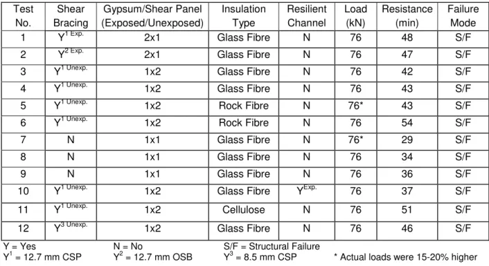
Table 1. Wood-stud wall assembly parameters and fire resistance test results.
Test Shear Gypsum/Shear Panel Insulation Resilient Load Resistance Failure
No. Bracing (Exposed/Unexposed) Type Channel (kN) (min) Mode
1 Y1 Exp. 2x1 Glass Fibre N 76 48 S/F
2 Y2 Exp. 2x1 Glass Fibre N 76 47 S/F
3 Y1 Unexp. 1x2 Glass Fibre N 76 42 S/F
4 Y1 Unexp. 1x2 Glass Fibre N 76 43 S/F
5 Y1 Unexp. 1x2 Rock Fibre N 76* 43 S/F
6 Y1 Unexp. 1x2 Rock Fibre N 76 54 S/F
7 N 1x1 Glass Fibre N 76* 29 S/F
8 N 1x1 Glass Fibre N 76 34 S/F
9 N 1x1 Glass Fibre N 76 36 S/F
10 Y1 Unexp. 1x2 Glass Fibre YExp. 76 37 S/F
11 Y1 Unexp. 1x2 Cellulose N 76 51 S/F
12 Y3 Unexp. 1x2 Glass Fibre N 76 46 S/F
Y = Yes N = No S/F = Structural Failure
Y1 = 12.7 mm CSP Y2 = 12.7 mm OSB Y3 = 8.5 mm CSP * Actual loads were 15-20% higher
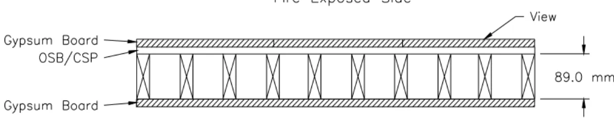
The wall assemblies were 3048 mm high by 3658 mm wide with various depths depending on the number of layers of gypsum board and shear membrane. Columns 2 and 3 in Table 1 indicate the placement of the shear membrane. A typical shear wall assembly is given in Figure 1. The materials used in the wall assemblies are gypsum board, wood framing, shear wall panel and insulation. The gypsum board is Type X gypsum board (Westroc “Fireboard” C/Type X), with thickness of 12.7 mm. The wood studs used were nominal 2x4’s (SPF No. 2, S-Dry, 38 mm thick by 89 mm deep) and spaced at 400 mm o.c. Prior to the assembly being constructed, the wood studs were conditioned at room temperature. The shear wall panel used was CSP or OSB 8.5 mm and 12.7 mm thick. Three types of insulation were used in this test series, namely, glass fibre, rock fibre and dry blown cellulose. Rock and glass fibre batts were 89 mm thick by 381 mm wide and 1194 mm long. For one assembly, resilient channels were used and attached to the fire-exposed side of the wood studs, using steel screws spaced at 300 mm o.c. Eight rows of channels were installed horizontally, perpendicular to the studs, at 400-mm o.c.
Type K chromel-alumel thermocouples were used to measure the temperatures at a number of locations throughout an assembly. The deflection at the unexposed surface was measured at nine different
locations. The wood stud shear wall assemblies were tested in a propane-fired vertical furnace in accordance with CAN/ULC-S101-M89 (ULC 1989). The assemblies were sealed at the edges against the furnace using ceramic fibre blankets. The furnace temperature was measured by nine shielded thermocouples. The average of the nine-thermocouple temperatures was used to control the furnace temperature. The load calculations were carried out based on the material characteristics of the wall. The applied loading, through eight hydraulic jacks, on the wall assemblies is given in Table 1. During the test, the furnace and wall assembly temperatures, deflections and the gauge pressure of the loading system were recorded at 1-minute intervals. The time to failure is based on failure criteria derived from CAN/ULC-S101-M89 (ULC 1989); i.e., thermal failure, integrity failure or stability failure. Complete details on the construction of the wall assemblies, instrumentation location and test procedures are given in Kodur et al. (1996 and 2000).
Figure 1. Typical wood stud wall assembly with shear membrane on the fire exposed side.
3. EXPERIMENTAL RESULTS AND DISCUSSION
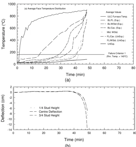
The results of the 12 full-scale fire resistance tests are given in Table 1 in which the time and mode of failure are given for each assembly. For all wall assemblies, the unexposed surface temperature at the time of structural failure was below the thermal failure criteria. All wall assemblies failed structurally through excessive deflection. The typical temperature distribution at the various locations in Test No. 1 is shown in Figure 2a, while the measured deflections are shown in Figure 2b. Detailed results, including temperatures and deflections measured during the fire tests on gypsum board protected, wood-stud shear wall assemblies, are provided in Kodur et al. (1996 and 2000). Results from the tests have indicated the two factors, which significantly influenced the performance of the wall assemblies, were the presence of the shear membrane and the type of insulation in the wall cavity. Other influences include the presence of resilient channels.
3.1 Effect of Shear Membrane
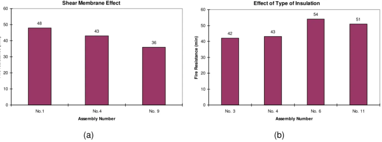
From Table 1, it can be seen that the fire resistance of the wall assembly with a shear membrane (Test No. 1) is 41% higher than the assembly without shear membrane (Test No. 8). This could be attributed to the additional stiffness provided by the shear membrane. Further, the presence of a shear membrane on the fire-exposed side protected the studs, which in turn delayed the strength loss of the wall assembly. The additional stiffness provided by the shear membrane delayed the deflection propagation in the wall, as compared to the wall with no shear membrane. The influence of a shear membrane on the fire resistance of wood stud shear walls is also shown in Figure 3a for Tests No. 1, 4 and 9 for which structural failure occurred at 48, 43 and 36 minutes, respectively. The results show that the addition of a shear membrane in a 1x1 wall assembly increases the fire resistance, with the greater increase occurring when the shear membrane is placed on the fire-exposed side of the assembly (Tests No. 1 and 4). The results also show that the wall with a thinner shear membrane provided slightly higher fire resistance as indicated by Tests No. 3 and 12, which provided 42 and 46 min, respectively. This could be attributed to the positive benefit obtained from the enhancement of eccentricity (of load), resulting from the shifting of centre of gravity, which occurs due to the loss of cross sectional area of the stud. Further research is
needed to determine the exact mechanism and to quantify the benefit of this effect. Finally, in order to investigate the effect of type of shear membrane on fire resistance, Tests No. 1 and 2 were conducted with OSB and CSP, respectively, as shear membrane on the fire exposed side of the wall. The fire resistance obtained for the shear wall assembly was 48 minutes with plywood and 47 minutes with OSB. These results indicate that the type of shear membrane does not significantly influence the fire resistance performance of the assembly.
Time (min) 0 10 20 30 40 50 60 70 80 T e mperature (°C) 0 200 400 600 800 1000 FL/Cav. (UnExp.) Mid. WStd. BL/Cav. (Exp.) BL/WStd (Exp.) ULC Furnace Temp. (a) Average Face Temperature Distribution
BL/FL (Exp.) (Rm. Temp. + 140°C) Failure Criterion 1 Average Values UnExp. FL/WStd. (UnExp.) (a) Time (min) 0 10 20 30 40 50 60 70 80 Defl ection ( c m ) -14 -12 -10 -8 -6 -4 -2 0
2 (b) Deflection Measurements - Stud 6
3/4 Stud Height, Stud 6 (8) Centre Deflection, Stud 6 (5) 1/4 Stud Height, Stud 6 (2)
(b)
Figure 2. Typical measured temperature distribution and deflection for Test No. 1.
3.2 Effect of Insulation Type
The type of insulation also played a major role on the performance of the shear wall assemblies exposed to fire. Results from fire resistance tests on Assemblies 3, 4, 6 and 11 can be used to indicate the effect of insulation types on the fire resistance of load-bearing wood stud shear walls (see Figure 3b). The failure of wall assemblies with the glass fibre insulation (Tests No. 3 and 4) occurred at 42 and 43 minutes respectively, while the failure of wall assemblies with the rock fibre (Test No. 6) and cellulose insulation (Test No. 11) occurred at 54 and 51 minutes, respectively. These results suggest that the use of cellulose fibre insulation provide a higher fire resistance compared to glass fibre insulation, but a lower fire resistance compared to rock fibre insulation. This can be attributed to the fact that when gypsum board at the exposed face fell off, the insulation was exposed to furnace heat. In the assembly with glass fibre insulation, the insulation melted and both sides of the stud and shear membrane were exposed to heat, while in the assembly with either rock fibre or cellulose fibre, the insulation remained in place and protected both the shear membrane and stud on both sides for an additional period of time. The rock fibre and cellulose fibre insulation played a significant role in limiting the temperature rise in the centre of the stud and shear membrane. This slow rise in temperature reduced the strength loss in the studs thus
increasing its fire resistance. As the insulation remained in-place after the gypsum fall-off, it protected the plywood membrane on the unexposed side and consequently, enhanced the stiffness of the wall.
Shear Membrane Effect
48 43 36 0 10 20 30 40 50 60
No.1 No.4 No. 9
Assembly Number F ir e r esi stan c e (m in )
Effect of Type of Insulation
42 43 54 51 0 10 20 30 40 50 60
No. 3 No. 4 No. 6 No. 11 Assembly Number F ir e R e s istan ce (m in ) (a) (b)
Figure 3. Effects of shear membrane, its location and type of insulation.
3.3 Effect of Resilient Channels
Tests No. 3 and 10 were conducted to investigate the effect of resilient channels on the fire resistance rating of load-bearing wood stud shear walls. The failure in Test No. 10 with resilient channels occurred at 37 minutes while in Test No. 3 (without resilient channels) the failure occurred at 42 minutes. These results indicate that for an assembly with the resilient channel located on the fire-exposed side of the wood stud shear wall, the fire resistance decreases by about 12%. This may be attributed to the formation of cavities between the insulation and gypsum board, which allow for the flame to travel early inside the assembly.
More details of the influence of all parameters are given in Kodur et al. (1996 and 2000).
4. BEHAVIOUR OF WOOD-STUD WALLS UNDER FIRE EXPOSURE
To develop a fire resistance model for load-bearing wall assemblies (without shear membrane) that replicates test results, the fire resistance behaviour from the experimental program must be carefully observed. From tests, by exposing a wood-frame wall to fire, the temperature in the gypsum board protection begins to increase first. After some time, the studs start to heat up, then they char. This causes the studs to deflect away from the fire. The deflection of the studs and the gypsum board increases gradually, leading to opening of the gypsum board joints. The gypsum board, attached to the studs, disables any lateral torsional buckling of the studs, so the wood studs deflect around its strong axis. As the opening increases, the wood studs become more exposed to fire and heat and the charring rate increases. For load-bearing wood walls, the heating and onset of charring of the stud create an eccentric load that can either be allowed to move or stay in place depending on the wall-end conditions (hinged vs. fixed conditions). As the cross-section area of the load-bearing studs starts diminishing (thickening of the charred area), the wall studs start experiencing excessive deflection and the load cannot be held by the studs any longer (buckling failure); this defines the structural failure of the wall. In the case of non-load-bearing walls, assembly failure is governed mainly by excessive temperature rise on the unexposed side of the wall, which only requires a heat transfer calculation.
5. DESCRIPTION OF THE FIRE RESISTANCE MODEL
NRC, in collaboration with FCC, has developed an analytical model for predicting the fire resistance of wood-stud wall assemblies. The model is based on observations from this and other sets of test data and couples a heat transfer sub-model and a structural sub-model. The heat transfer sub-model predicts the temperature profile inside the wood-stud wall and the time to insulation failure. The structural sub-model uses the temperature profile to calculate the degradation of the mechanical properties at elevated temperatures, cross-section reduction, the deflection of the wood studs and the time to structural failure of the assembly. The two sub-models are physically independent and are explained below.
5.1 Thermal Response Sub-model
The thermal response is predicted using a finite difference heat transfer sub-model developed by FCC. The sub-model, called WALL2D, will be only briefly explained in this section, as it has been published elsewhere (Takeda and Mehaffey 1998). WALL2D determines the temperature distribution in the wall as a function of time, taking into account the heat absorbed in the dehydration of gypsum and wood, and in the pyrolysis of wood, without considering mass transfer. The heat transfer, through gypsum boards and wood studs, is described using an enthalpy formulation. The sub-model assumes that heat transfer occurs mainly in the cross-section of the wall assembly and that heat flow in the vertical direction can be ignored. The finite difference mesh considers symmetry of the wall, with a mesh refinement in proximity of the wood stud and larger spacing within the gypsum board far from the wood stud.
In assessing the thermal behaviour, WALL2D uses thermo-physical properties of wood, gypsum board, and insulation, based on experimental tests conducted at NRC as well as values found in the literature (Takeda and Mehaffey 1998). WALL2D also predicts the effect of glass-fibre and rock-fibre insulation on the fire resistance of wood-stud walls. This effect is considered by combining conduction and radiation heat transfer through the insulation, and is represented by a temperature-dependent effective thermal conductivity and density of the insulation. In addition, WALL2D calculates the flow of hot gases through the opening into the stud cavity based on shrinkage of gypsum board and opening of the joints, as well as the advance of the char layer into the cross-section of the stud with time.
5.2 Structural Response Sub-model
The structural fire performance of wood-frame assemblies is affected by the rate of charring, degradation of the mechanical properties of the wood at elevated temperatures and the load sustained by assemblies. 5.2.1 Elastic buckling load calculation
To determine the structural response, a critical buckling sub-model is implemented with WALL2D. The sub-model uses the temperature distribution predicted by WALL2D as an input, then calculates the deflection and the critical elastic buckling-load for a wood-stud wall. The buckling of the wood studs is restricted to the strong axis because of the lateral support by the gypsum board. The critical elastic buckling-load, assuming both ends of the studs are pinned, is given by:
[1]
( )
2 2 cr KL EI P = πwhere Pcr is the elastic buckling-load (N), E is the modulus of elasticity of the resisting member (MPa), I is
the moment of inertia (mm4), and KL is the effective stud length (mm), with K = 1 in this case. The values of the moment of inertia and modulus of elasticity change with time. For the moment of inertia, the temperature profile and pre-set charring temperature provide an estimation of the remaining cross-section of the stud, thus allowing for calculation of the time-dependent moment of inertia. For the modulus of elasticity, the change with temperature is obtained from the literature (Schaffer 1970). Structural failure is assumed to occur when the load applied on the wall exceeds the critical buckling-load. The structural
sub-model calculates the rigidity (product of the modulus of elasticity and the moment of inertia) at a particular time, for each stud in the wall and based on meshing the stud, as follows:
[2]
(
)(
i)
2 i m i i i m i 3 i i i bD Y y E 12 D b E EI=å
+å
−where bi is the element width (mm), Di is the element depth (mm), Y is the stud centroid (mm) which
moves with time, yi is the element centroid (mm), and Ei is the temperature/moisture-dependent modulus
of elasticity of the element (MPa) (Schaffer 1970). 5.2.2 Calculation of deflection
The stud’s deflection is estimated using the theory of elasticity. At ambient conditions, the applied force and the centre of resistance of the wood stud are assumed to act at the centroid of the stud’s cross-section. As temperatures start to increase, the fire-exposed side of the wood stud begins losing some of its strength and the unexposed side remains strong. This unbalance in strength results in a shift of the centre of resistance towards the cooler area, thus creating an eccentricity of the centroid, ec. Due to this
eccentricity, a moment is created. In addition, the elements reaching a temperature in the range of 280 to 300°C start charring, leading to a shift, ep, of the applied force from its original position. The net
eccentricity is calculated as the difference between ec and ep. The deflection of the stud, as predicted for
a hinged-hinged eccentric column, can be calculated by considering the stud as a beam-column structure. The differential equation giving the deflection can be written as follows:
[3] 0EIy′′′′+Py′′=
where y is the out-of-plane deflection (mm), EI is the stud rigidity (N-mm2) (see Equation 2), and P is the applied load (N). The general solution of Equation 3 is:
[4] x Cx D EI P sin B x EI P cos A y ÷÷+ + ø ö ç ç è æ + ÷ ÷ ø ö ç ç è æ =
where A, B, C and D are constants determined from boundary conditions and x is the co-ordinate along the stud height. Solving this equation gives the deflection, y, at any height x on the stud at any time, as:
[5] ú ú ú ú û ù ê ê ê ê ë é Ψ Ψ Ψ − ÷ ø ö ç è æ Ψ − Ψ = ) cos( ) cos( x L 2 cos 2 EI 8 L M ) x ( y 2 2 0 with cr P P 2 π = Ψ and M0 =P(ec −ep)
where L is the length of the stud (mm), ec is the eccentricity of the centroid of the resisting member (mm),
and ep is the applied load eccentricity (mm). The maximum out-of-plane deformation, ymax, occurs at
mid-height (x = L/2) thus: [6]
(
)
ú ú û ù ê ê ë é Ψ Ψ Ψ − ú ú û ù ê ê ë é − = ) cos( ) cos( 2 EI 8 L e e P y 2 2 p c max6. COMPARISON OF MODEL PREDICTIONS WITH EXPERIMENTAL DATA
At this stage of the development, the model predictions are limited to load-bearing wood-stud walls, protected by gypsum board only and does not include the effect of shear membranes. Therefore, analytical predictions will be carried out for those assemblies that do not contain any shear membrane. Fire resistance tests for Assemblies No. 8 and 9 were used to evaluate the predictions by the fire resistance model. Details of the assemblies are shown in Table 1. Due to space limitation, the comparison figures will be shown for time to structural load failure and out-of-plane deflection for Test No. 8 only. The predictions of time-temperature curves generated by the heat transfer have been used to calculate the reduction in load carrying capacity of the studs and the degradation in the modulus of elasticity, which was assumed to be equal to 7000 MPa at ambient temperature (low percentile range). Temperatures on the unexposed sides did not reach the insulation failure criterion, as both assemblies failed by structural instability at 34 and 36 minutes for Tests No. 8 and 9, respectively. Table 2 summarizes the model predictions and experimental results. The model predicts conservatively the onset of charring, with a difference of about 15% for Test No. 8 and 10% for Test No. 9.
Table 2. Comparison between tests results and model predictions. Onset of Char (min) Insulation Failure (min) Structural Failure (min) Test No.
Test Model Difference Test Model Test Model Difference
8 20.0 17.0 15% N/A 48.0 34.0 33.0 3%
9 19.0 17.0 10% N/A 48.0 36.0 33.0 8%
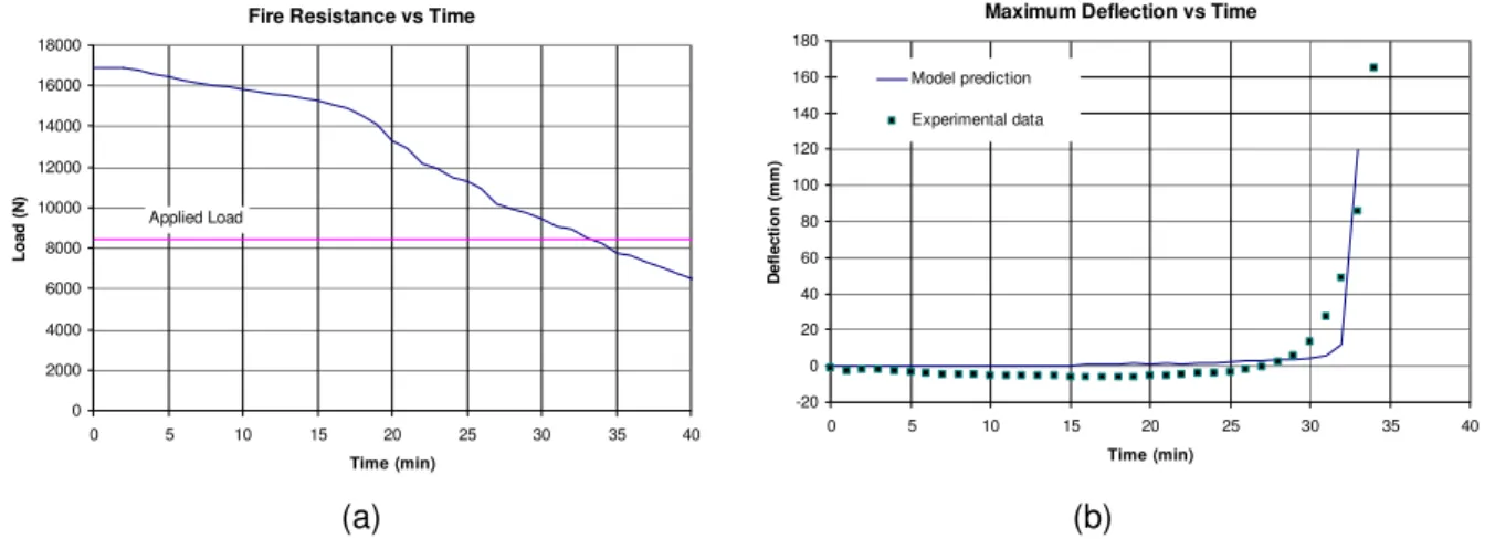
To measure the performance of the structural response model, the theoretical predictions of the structural fire resistance and deflection at mid-height are evaluated. Figure 4a illustrates the critical elastic buckling-load versus time as predicted by the structural response sub-model. The fire resistance decreases with increasing time because the value of the modulus of elasticity decreases with time and the cross-section of the studs reduces after charring. The intersection of the horizontal line, at the level of the applied load (8.45 kN), with the elastic buckling-curve, represents the theoretical time to structural failure of the wall. This time is 33 minutes for both assemblies, while the times to structural failure measured experimentally are 34 and 36 minutes for Tests No. 8 and 9, respectively. Therefore, the model predictions are very close to the test results, with the analytical time to structural failure slightly underestimated by 3% and 8% for Tests No. 8 and 9, respectively. Table 2 also shows a summary of the model predictions and experimental results for the two tests.
Fire Resistance vs Time
0 2000 4000 6000 8000 10000 12000 14000 16000 18000 0 5 10 15 20 25 30 35 40 Time (min) Loa d ( N ) Applied Load
Maximum Deflection vs Time
-20 0 20 40 60 80 100 120 140 160 180 0 5 10 15 20 25 30 35 40 Time (min) D e fl ecti o n ( m m ) Model prediction Experimental data (a) (b)
The maximum mid-height deflections are also plotted versus time for both the analytical predictions and the test results (see Figure 4b). As shown in this figure, the deflection is very small in the first 30 minutes. After this, the model predictions and the test measurements start increasing at a faster rate. The rate of increase in the model predictions is similar to that of the test results. The rate in the model, however, starts a few minutes later. The model slightly overestimates the deflection at 33 min.
7. WALLS TREATED AS AN ASSEMBLY SYSTEM
The fire resistance model described above is based on the elastic buckling theory of a single stud. However, in a wall assembly failure of one stud may not mean failure of the whole wall system. This is due to the possible redistribution of the load to the other studs, which did not fail, especially to those at the ends. It is sometimes suggested to cut the end studs so that they do not contribute to the load and realistic comparison may be made with model predictions that are based on the load on a single stud. In the tests presented here, the end studs were not cut (contributed to the load) and consequently we need to find another alternative to treat the walls as assembly systems. To achieve this, the following method was used:
• The wall assemblies tested contain 10 studs each: 1. 2 studs where joints open
2. 6 studs where joints do not open 3. 2 end studs
• Run the fire resistance model with 3 cases:
1. Simulation with joint opening (failure will occur first) 2. Simulation without joint opening (failure will occur next)
3. Simulation with conditions kept as ambient (failure will not occur)
• Calculate the total assembly resistance by adding the resistance from all cases with the appropriate coefficients (stud number) at each time step as: 2 x case1 + 6 x case2 + 1 case 3
• Compare the total resistance to the total applied load at every time step.
• Determine the fire resistance when the load becomes higher than the buckling resistance.
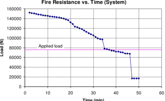
Figure 5 shows the buckling resistance of Tests No. 8 and 9 vs. time calculated based on the method described above. As illustrated in the figure, when the first 2 studs fail (at 33 min), the wall can still resist for 3 more minutes as the load is redistributed and being resisted by the studs that have not reached failure. The method, however, assumes that the end studs remain at ambient temperatures, which may not be realistic. Based on this, it can be concluded that using a model based on a single stud, as opposed to a complete system, may provide reasonable predictions that are always on the conservative side.
Fire Resistance vs. Time (System)
0 20000 40000 60000 80000 100000 120000 140000 160000 0 10 20 30 40 50 60 Time (min) Load ( N ) Applied load
8. SUMMARY, CONCLUSIONS AND FUTURE WORK
Based on the experimental studies presented in this paper, the following points can be summarized: 1. For load-bearing wood-stud wall assemblies, the installation of a CSP or OSB shear membrane
increases the fire resistance of the assembly.
2. The maximum increase in the fire resistance of an assembly occurred when the fire exposure was on the same side as the shear membrane.
3. For load-bearing wood-stud shear walls, the assembly with rock fibre or cellulose fibre insulation provided more fire resistance compared to a similar assembly with glass fibre insulation.
In addition, a fire resistance model developed by NRC was used to show comparisons with the results of 2 experimental full-scale wall tests exposed to CAN/ULC-S101-M89 fire (ULC 1989). The model indicates that the time to structural failure and lateral deflection of the studs at mid-height are reasonably well predicted. The current fire resistance model is suitable to assess the time to failure of load-bearing wood-frame wall assemblies for practical applications, using both the insulation and structural failure criteria. A method was proposed to evaluate the wall as a system. The comparison of the method prediction with the two tests showed a slight increase in the fire resistance. It could be concluded that the use of a single stud model provides reasonable and conservative results.
As a next step, the model will be validated against experimental data through an experimental test program that will include exposing full-scale, load-bearing wood-stud walls to both standard and non-standard fire exposures. In addition, the model will be re-evaluated to include the effect of shear membrane.
9. ACKNOWLEDGEMENTS
This research was funded by NRC and industry partners that included Canadian Wood Council, Canadian Home Builders Association, Canadian Sheet Steel Building Institute, Forintek Canada Corp., Owens-Corning Canada, Roxul Inc., Gypsum Manufacturers of Canada. The authors are grateful to John Latour, Patice Leroux, Roch Monette and Jocelyn Henrie for assisting in constructing the assemblies and conducting the tests.
10. REFERENCES
Canadian Commission on Building and Fire Codes (1995), National Building Code of Canada, Institute for Research in Construction, National Research Council of Canada, Ottawa, Canada.
CAN/ULC-S101-M89 (1989) Standard Methods of Fire Endurance Tests of Building Construction and
Materials, Underwriters' Laboratories of Canada, Scarborough, Ontario, Canada.
Kodur, V.K.R. Sultan, M.A. and Denham, E.M.A. (1996) Temperature Measurements in Full-Scale Wood Stud
Shear Walls, Internal Report No. 729, Institute for Research in Construction, National Research Council,
Ottawa, Canada.
Kodur, V.K.R. and Sultan, M.A. (2000) Performance of Wood Stud Shear Walls Exposed to Fire, Fire and
Materials, 24: 9-16.
Kodur, V.K.R. Sultan, M.A. Latour, J.C. Leroux, P. and Monette, R.C. (2000) Fire Resistance Tests on
Cellulose and Glass Fiber Insulated Wood Stud Shear Walls, Internal Report No. 806, Institute for
Research in Construction, National Research Council, Ottawa, Canada.
Schaffer, E.L. (1970) Elevated Temperature Effect on the Longitudinal Mechanical Properties of Wood, Ph.D. Thesis, Department of Mechanical Engineering, Univ. Wisconsin, Madison, USA.
Takeda, H., and Mehaffey, J.R. (1998) WALL2D: A Model for Predicting Heat Transfer through Wood-Stud Walls Exposed to Fire,” Fire and Materials, 22: 133-140.