Publisher’s version / Version de l'éditeur:
Journal of Thermal Insulation and Building Envelopes, 20, January, pp. 191-198,
1997-01-01
READ THESE TERMS AND CONDITIONS CAREFULLY BEFORE USING THIS WEBSITE. https://nrc-publications.canada.ca/eng/copyright
Vous avez des questions? Nous pouvons vous aider. Pour communiquer directement avec un auteur, consultez la première page de la revue dans laquelle son article a été publié afin de trouver ses coordonnées. Si vous n’arrivez pas à les repérer, communiquez avec nous à [email protected].
Questions? Contact the NRC Publications Archive team at
[email protected]. If you wish to email the authors directly, please see the first page of the publication for their contact information.
NRC Publications Archive
Archives des publications du CNRC
This publication could be one of several versions: author’s original, accepted manuscript or the publisher’s version. / La version de cette publication peut être l’une des suivantes : la version prépublication de l’auteur, la version acceptée du manuscrit ou la version de l’éditeur.
Access and use of this website and the material on it are subject to the Terms and Conditions set forth at
Evaluation of five simple ventilation systems suitable for houses
without forced-air heating
Reardon, J. T.; Shaw, C. Y.
https://publications-cnrc.canada.ca/fra/droits
L’accès à ce site Web et l’utilisation de son contenu sont assujettis aux conditions présentées dans le site
LISEZ CES CONDITIONS ATTENTIVEMENT AVANT D’UTILISER CE SITE WEB.
NRC Publications Record / Notice d'Archives des publications de CNRC:
https://nrc-publications.canada.ca/eng/view/object/?id=7b363756-6404-47b5-86a4-9c8eb3748d94 https://publications-cnrc.canada.ca/fra/voir/objet/?id=7b363756-6404-47b5-86a4-9c8eb3748d94
http://www.nrc-cnrc.gc.ca/irc
Eva lua t ion of five sim ple ve nt ila t ion syst e m s suit a ble for house s
w it hout forc e d-a ir he a t ing
N R C C - 4 0 2 9 8
R e a r d o n , J . T . ; S h a w , C . Y .
J a n u a r y 1 9 9 7
A version of this document is published in / Une version de ce document se trouve dans:
Journal of Thermal Insulation and Building Envelopes,
20, January, pp.
191-198, January 01, 1997
The material in this document is covered by the provisions of the Copyright Act, by Canadian laws, policies, regulations and international agreements. Such provisions serve to identify the information source and, in specific instances, to prohibit reproduction of materials without written permission. For more information visit http://laws.justice.gc.ca/en/showtdm/cs/C-42
Les renseignements dans ce document sont protégés par la Loi sur le droit d'auteur, par les lois, les politiques et les règlements du Canada et des accords internationaux. Ces dispositions permettent d'identifier la source de l'information et, dans certains cas, d'interdire la copie de documents sans permission écrite. Pour obtenir de plus amples renseignements : http://lois.justice.gc.ca/fr/showtdm/cs/C-42
INFORMATION AND TECHNOLOGY TRANSFER
Evaluation of Five Simple Ventilation
Systems Suitable for Houses without
Forced-Air Heating*
JAMES T. REARDON AND CHIA-YU SHAW
Institute for Research in Construction National Research Council Canada
Ottawa, Ontario KIA OR6 Canada
INTRODUCTION
A
DEQUATE VENTILATION ISessential in houses to ensure acceptablein-door air quality and to control condensation. In Canada, this means that not only does the ventilation rate for the whole house meet the mended value but also all individual rooms in the house receive their recom-mended ventilation rates, as specified in the Canadian standard CAN/CSA-F326-M91 "Residential Mechanical Ventilation Systems" [1]. Those requirements have already been adopted into the 1993 Ontario Building Code [2] and the 1995 National Building Code of Canada [3].
The new ventilation performance standards present tremendous chal-lenges for house builders to meet the ventilation air distribution require-ments without installing a complete, fully-ducted, forced-air heating, and ventilation system. They may also make it difficult for alternative heating systems, such as electric baseboards and hydronic systems, to comply with the new building codes. Work has been carried out by others, such as the Canada Mortgage and Housing Corporation and the Ontario New Home Warranty Program, to develop designs that will satisfy the CSA F326
re-quirements for houses with forced-air heating systems. The project
described in this paper examined simplified ventialtion system designs
*Reprinted for the 3rd Canada/Japan Housing R&D Workshop Ottawa, 9-12, June, 1996, with permission.
J. THERMAL'NSUL. AND BLDG. ENVS. Volume. 20-January 1997 191
1065-2744/97/030191-08 $10.00/0 ©1997 Technomic Publishing Co., Inc.
192 JAMEST. REARDON AND CHIA¥YUSHAW
suitable for houses that do not have the ducted air delivery system of forced-air heating.
THE VENTILATION SYSTEMS
Five ventilation systems were considered in this project [4]. Four were exhaust-only systems and one was a balanced system. Two exhaust-only systems used either only typical local exhaust fans in the kitchen and bath-rooms, one without any inlet vents (Configuration A) and one with deli-berate inlet vents distributed among the bedrooms and the main floor living areas. (Configuration B). The other two exhaust-only systems combined or included a partially distributed centralized exhaust (PDE) system on the sec-ond floor with pick-up grilles in each bedroom in addition to the kitchen and bathroom fans, one without any inlet vent (ConfigurationC) and one with a single centralized inlet vent (Configuration D). For each of these exhaust-only approaches without inlet vents, make-up air was provided either through one or more deliberate passive inlet vents or by air leakage 'through accidental openings in the exterior building envelope. The balanced system (Configuration E) used the kitchen and bathroom fans for its exhaust side and a minimal ducted supply (MDS) system for its supply side. The minimal ducted supply system was sized to provide only ventilation air re-quirements (SLIs toallrooms except 10 Lis to the master bedroom and the basement [5]), not the larger flow rates required in a forced-air heating system to meet thermal loads.
EXPERIMENTAL APPROACH
These various ventilation system designs were tested experimentally by installing them in the NRC/IRC two-storey research house. This house was
built using conventional modern Canadian wood-frame construction
methods in 1989, and included a full-depth poured concrete basement. The air distribution performance ofeach system was measured, using both single and multiple tracer gas decay techniques, for the full range of typical Cana-dian weather conditions during a late autumn to late spring combined heating/shoulder season in Ottawa. The existing electric forced-air heating system originally installed in the research house provided two reference
cases for useful comparison with the various test ventilation systems: the
house with all windows, doors, and vents closed and both with (Configura-tion G) and without (Configura(Configura-tion F) the furnace fan operating continu-ously to circulate the leakage air within the house interior. '
For the single tracer gas tests, either SF, or N,O tracer gas was dosed into the whole house and mixed to a uniform concentration before the doors to
Five Ventilation Systems Suitable for Houses without Forced-Air Heating 193 the bedrooms, bathrooms. and basement were closed and the test ventilation
system operation was started. For the multiple tracer gas tests, SF6 was dosed
into the sealed master bedroom and N,O was dosed into the rest of the house. The two gases were mixed within their respective zones to uniform concentrations before unsealing the master bedroom door, closing the doors to the other bedrooms, bathrooms, and the basement and starting the opera-tion of the test ventilaopera-tion system. The concentraopera-tions of either or both tra-cer gases in each room were monitored continuously during the entire mix-ing and decay periods usmix-ing an absorptive infrared analyzer (N,O) and a gas chromatograph (SF,) and were recorded by a computerized data acquisition system. The flow rates through all the mechanical ventilation components, (fans and ducts) were continuously monitored during each test to ensure consistent mechanical ventilation conditions were maintained.
TEST RESULTS
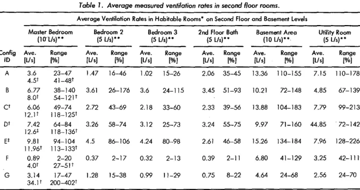
The concentration decay data measured in each room for the single tracer gas tests were fitted with an exponential curve to determine their apparent local air change rates, which in turn were multiplied by room ,volumes to calculate the apparent fresh air supply flow rates for each room. For each ventilation system configuration, averages of these measured flow rates for each room were calculated, and are listed, along with their ranges expressed as percentages of the room requirements, in Tables 1 and 2 for rooms on the second floor and in the basement, and for rooms on the ground floor, re-spectively.
The multiple tracer. gas tests were originally intended to provide some in-dication of the interzonal airflows between the master bedroom, the rest-of-the-house (as a single zone), and the outdoors. Attempts to use multiple tracer gas interzonal air flow calculation techniques [6] were unsuccessful, even for Configuration G where the furnace fan operation provided well-mixed concentrations throughout the rst-of-the-house as a single Zone (the best case). However, the decay of the SF6 dosed only in the master bedroom did provide some useful estimates of the total air change rate within the master bedroom (including outside air and interior air flowing from other rooms into the master bedroom). The averages of the supply flow rates calculated from these total air change rates for each ventilation system con-figuration are also listed in Table 1 as second entries in the Master Bedroom
column. '
Also listed in Tables 1 and 2 are the individual rooms' ventilation rates re-quired by the CSA F326 standard. The single tracer gas tests' results indicate that the local exhaust system both without and with deliberate passive inlet vents (Configurations A and B) do not provide adequate ventilation for the
-'"
Table 1. Average measured ventilation rates in second floorrooms.
....
Average Ventilation Rates in Habitable Rooms'" on Second Floor and Basementlevels
Master Bedroom Bedroom 2 Bedroom 3 2nd Floor Both Basement AreQ uエセゥエケ Room
(10'1/s)" (5 Us)" (5 Us)" (5 lis)" (10 Us)" (5 lis)"
Config Ave. Range Ave. Range Ave. Range Ave. Range Ave. Range Ave. Range
10 IUs) [%] [Us] [%) IUs] I%J [Us) I%J [Us] [%) IUs] [%)
セ > A 3,6 23-47 1.47 16-46 1.02 15-26 2,06 35-45 13.36 110-155 7.15 110-178 ;::III 4.51 41-48 '
,...
B 6.77 38-140 3.61 26-176 3.6 24-115 3.45 51-93 10.21 72-148 4.85 67-139'"
': 8.01 54-121' セ"
0et
6.06 49-74 2.72 43-69 2.18 33-60 2.33 39-56 13.88 104-183 7.79 99-213 z 12.1 1 118-1251 >z"
01 7.42 64-84 3.26 58-74 3.12 25-73 3.24 55-75 9.97 71-160 44.85 . 72-142 n'"
12.61 118-1361セ
EI 9.81 94-104 4.5 86-106 4.24 80-98 2.61 46-58 15.26 134-184 7.96 128-226 c 11.961 113-133 ' セ'"
> F 0.89 2-20 0.37 2-17 0.32 2-13 0.39 2-11 6.80 41-129 3.25 42-111"
4.01 27-5]1 G 3.14 17_47 1.28 15-38 0.99 11-29 0.75 8-22 4.64 24-68 2.56 24-70 34.1 1 200-4021.. Habitable rooms do not include hallways or storage closets (CSA F326 standard) .
.. "Room ventilation rate requirements shown in parentheses, verified by measurement where applicable as indicated below.
t$econd entries for master bedroom are results from multiple tracer gas tests' SF6 decoy curvefitsindicating fatal airflow into MBR zone.
tBedrooffi, bathroom, and kitchen exhausts measured ond verified for PDE tests (Configuroitons C and D). tSupply rates to off rooms and 011 exhaust rates meosured and verified for MDS tests (Configuration E).
Me
ᄋ⦅Lᄃw[セᆬGエBセセ^MBBセセセイXyMGnゥ・ c<,,, BLセ」BL ,>,,, ,,,,", [MZ[LJセjGゥPLM[LッᆬZBLL[[GエセGAEJG[ャスセ[ZL[LッO[|[ォMBBGGCCjZZセᄃセZZイtiG[MAj⦅Table2. Average measured ventilation rates in first Roarrooms.
Average Ventilation Rates in Habitable Rooms· on Ground Floor Kitchen Dining Room living Room Family Room
(5 l/s)-- (5 lIs)-- (5 lIs)-- (5
lIs)--Config Ave. Range Ave. Range Ave. Range Ave. Range
ID [Us] [%] [Us] [%] [Us] [%] [Us] [%]
A 5.20 87-130 5.47 98-137 5.46 92-137 5.21 88-131 8 10.1 145-319 11.7 181-352 9.85 136-278 9.33 128-277
et
5.88 99-147 6.16 107-151 6.12 103-143 5.77 100-133 Dt 7.98 127-201 8.27 133-206 7.14 94-214 6.65 83-199E'
4.80 84-108 4.87 84-110 5.26 93-128 4.97 87-123 f 1.81 19-76 1.84· 20-78 1.99 21-83 1.86 19-76 G 1.37 16-40 1.37 17-39 1.47 18-44 1.36 17-41 *Habitable roomsdonot include hallways or storage closets (CSA F326 standard).** Room ventilation rate requirements shown in parentheses.
tBedroom, bathroom, and kitchen exhausts measured and verified for PDE tests lConfiguroitons C and D). :l:Supply ratesto all rooms and all exhaust rates measured and verified for MDS tests (Configuration E).
セ
セ"
".
;;-g. Powder Room"
en (5lIs)--""
Ave. Rangeセ
[Us] [%] enセ セN 0.70 11-18 セ""
1.22 17-36 '0>セ 0.79 13-19 セ 0.98 14-26 ;;;1Jl 0.80 13-18 §::セ 0.32 3-10..
..
0.19 2-5 :J1 セ セ...
セ セN;::
..
セN-'"
<on196 JAMEST. REARDON ANDCHIAMYU SHAW
bedrooms but either satisfy (A) or exceed (B) the ventilation requirements for the ground floor and basement rooms. The partially distributed exhaust system (Configurations C and D) similarly fail to provide adequate ventila-tion for the bedrooms but either meet or exceed the requirements for the ground floor and basement rooms. The minimal ducted supply system
comes the closest to meeting consistently the ventilation requirements for each room.
The total of the average supply flow rateS for most ventilation system con-figurations tested failed to sum to the total of the directly measured mechanical exhaust flow rates for those configurations (65 Lis for A, Band E; 70 Lis for C and D). This suggests that the multiple zone single tracer gas decay analysis technique used here may not be completely valid for the con-ditions of these tests. It is useful to compare the multiple tracer gas tests' results for SF, decay in the master bedroom with the corresponding results from the single tracer gas tests' results. The MTG results suggest that the local exhaust system indeed failed to provide adequate air flow to the master bedroom either with or without deliberate vents. The MTG results also sug-gest that the PDE and the MDS systems both provide adequate ventilation
air flow to the MER, in accord with the direct flow rate measuremetns through the mechanical ventilation components.
CONCLUSIONS
The results of the experiments on the local exhaust-only strategy led to the following conclusions.
• The kitchen and bathroom fans alone do not meet the overall house air
change criterion, despite their total measured exhaust being equal to the
whole house ventilation requirement, nor do they provide adequate air
distribution to the various individual rooms.
• With make-up air provided only by air leakage, the ground floor storey's
rooms are adequately ventilated, the basement rooms are overventilated, but the critical bedroom areas are unclerventilated.
• When supplemented by deliberate passive inlet vents distributed in the second storey bedrooms and in the main floor rooms, the house overall
was overventilated, with the ground floor rooms substantially
overven-tilated receiving virtually all the incoming outdoor air supply, the base-ment rooms adequately ventilated, while the closed bedrooms still received less ventilation air than recommended by the standard.
Despite the overall excess ventilation with deliberate passive inlet vents open, closed bedrooms still received too little ventilation air.
Five Ventilation Systems Suitable Jor Houses without Forced-Air Heating 197
be characterized as a centralized single-point exhaust system with
distrib-uted passive supply either via accidental leaks or via deliberate purpose-provided inlet vents. The distributed passive vents did not serve successfully
as air inlets in the second storey bedrooms, but instead served as exfl1tration
sites and, matched by the deliberate openings in the lower envelope, helped
to increase the overall air change rate for the house, primarily driven by stack
effect.
The experiments on the partially distributed exhaust system produced
more encouraging results.
• Both with and without deliberate make-up air venting, this strategy
pro-vided better air distribution to the critical closed bedrooms on the second
floor.
• With only accidental air leakage as the make-up air supply, not quite enough outdoor air was provided to the bedrooms to fully comply with
the new standards, despite sufficient measured exhaust from each bedroom. For the same conditions, the ground floor rooms were
ade-quately supplied with outdoor air, and the basement rooms were
somewhat overventilated.
• With a single centralized passive inlet opening, however, the bedrooms were better ventilated, the basement rooms were adequately ventilated, and the ground floor rooms experienced modest overventilation.
For the second storey, this system could be characterized as a distributed mechanical exhaust with a single centralized passive supply. This strategy was judged as suitable for further development. By providing only one pas-sive inlet, relatively centralized with regard to building height and probably
near the neutral pressure level, this arrangement was not so susceptible to
stack effect dominance as was the distributed passive venting arrangement of
the local exhaust fan strategy above. However, the influence of the passive vents in both the local exhaust system and the PDE system seems to have lowered the house's neutral pressure level, which was reflected in the decreased air supply (by leakage) into the basement room.
The experiments on the minimal ducted supply system balanced with the local exhaust fans confirmed that this mechanical supply strategy success-fully provided adequate outdoor air supply and good air distribution to all the rooms in the house. Since it was a balanced approach, the background leakage of air contributed to but did not dominate the interior air flow
pat-terns in these tests. This was demonstrated by modest excess ventilation in the basement rooms.
The single tracer gas technique used in this research seemed to be an
effec-tive method for determining the amount of fresh air supplied to each room
in the house. However, it tends to underestimate the ventilation rate
198 JAMEST. REARDON ANDchiaセyu SHAW
somewhat in rooms where the majority of inflow is from other rooms in the
house. The multiple tracer gas technique, while unable to quantitatively identify all the interzonal flow rates among all the rooms, was useful to com-plement the single tracer gas measurements of fresh air supply rates with
measurements of the total air supply rates to the master bedroom as an
illus-trative example. The verification of these methods was made possible by the
direct measurement of flow rates through each ventilation system
compo-nent for all the tests.
ACKNOWLEDGEMENTS
This research project was supported financially by the following organiza-tions and agencies: the Canadian Electrical Association, Canada Mortgage and Housing Corporation, Gas Technology Canada, the Electrical and
Elec-tronic Manufacturers Association of Canada (now Electro-Federation
Canada), and the National Research Council of Canada. That support is gratefully acknowledged.
REFERENCES
I. CSA. 1991. National Standard of Canada CAN/CSA-F326-M91, Residential
Mechanical Vet/lilation Systems. Rexdale, Ontario, Canada: Canadian Standards
Association.
2. 1993.Ontario Building Code,Ed.. , Ontario Ministryof Housing, Government of the Province of Ontario, Toronto, Ontario,
3. 1995. National Building Code
if
Canada, Ed., Institute for Research in Construc-tion, National Research Council of Canada, Ottawa, Ontario.4. Reardon, J. T. 1995. "Ventilation Systems for New and Existing Houses with
Baseboard Heating;'Report CEA9229U967, prepared for the Canadian Electrical
Association by the Institute for Research in Construction, National Research Council of Canada, October.
5. Reardon,]. T,T.Sawachi, H. Matsumoto and C. Y. Shaw. 1996. "Evaluation of Alternative Ventilation Distribution Systems Using the NRC/IRC Two-Storey Research House Facility;' submitted for presentation at the 3rd Canada Japan Advanced Houses Workshop, Ottawa, Ontario, April.
6. Enai, M.,C.Y.Shaw and]. T. Reardon. 1990. "On the Multiple Tracer Gas
Tech-niques for Measuring Interzonal Airflows in Buildings," ASHRAE 7Yansactions,