Publisher’s version / Version de l'éditeur:
Vous avez des questions? Nous pouvons vous aider. Pour communiquer directement avec un auteur, consultez la
première page de la revue dans laquelle son article a été publié afin de trouver ses coordonnées. Si vous n’arrivez pas à les repérer, communiquez avec nous à [email protected].
Questions? Contact the NRC Publications Archive team at
[email protected]. If you wish to email the authors directly, please see the first page of the publication for their contact information.
https://publications-cnrc.canada.ca/fra/droits
L’accès à ce site Web et l’utilisation de son contenu sont assujettis aux conditions présentées dans le site
LISEZ CES CONDITIONS ATTENTIVEMENT AVANT D’UTILISER CE SITE WEB.
Internal Report (National Research Council of Canada. Institute for Research in Construction), 1996-11-01
READ THESE TERMS AND CONDITIONS CAREFULLY BEFORE USING THIS WEBSITE.
https://nrc-publications.canada.ca/eng/copyright
NRC Publications Archive Record / Notice des Archives des publications du CNRC :
https://nrc-publications.canada.ca/eng/view/object/?id=ba1cbd49-d85e-45d0-9790-666f912096b0 https://publications-cnrc.canada.ca/fra/voir/objet/?id=ba1cbd49-d85e-45d0-9790-666f912096b0
NRC Publications Archive
Archives des publications du CNRC
For the publisher’s version, please access the DOI link below./ Pour consulter la version de l’éditeur, utilisez le lien DOI ci-dessous.
https://doi.org/10.4224/20338075
Access and use of this website and the material on it are subject to the Terms and Conditions set forth at FiRECAM System Model Documentation
R427
no. 732
c . 2
BLDG
FIRECAMTM
System
Model
~ocumentation
. I S < I / ~ C ~ S I NKL/LNKL i n ernax r e p o r t (Institute f
- CRC Ser ~ ~ - ' " N A L Y S E
F.
i e c e i v e d o n : 01-09-97
L n t e r n a l r e p o r t .
by C.R. Dutcher, D. Yung and G.V. Hadjisophocleous
Internal Report No. 732
Date of Issue: November 1996
This is an internal report of the Institute for Research in Const~ction. Although not intended for general distribution, it may be cited as a reference in other publications.
ABSTRACT
This document describes the FiRECAIvP system model as well as each of the individual submodels. The submodel linkaees and interactions are described alone with a summary of their respective results. ~dditknal sections of this report also descrige the F i R E C W input files and its contents, and the output data produced by a FiRECAMm
1
.
INTRODUCTION...
1. . 1.1 F i R E C W Descnpbon
...
11.2 Computer System Requirements
...
22
.
F i R E C W MODELS ... 22.1 Model Naming Convention
...
22.2 Model Temporary File Naming Convention
...
42.3 Location of Temporruy Files
...
42.4 Temporary File Contents and Structure
...
4...
2.5 Model Execution and Linkage 5...
3.
F i R E C W MODEL DESCRIPTIONS 9 3.1 BEVM-
Building Evaluation Model...
9...
3.2 FDRM - Fire Department Response Model 11 3.3 ECMD-
Economic Model...
133.4 BEFM - Boundary Element Failure Model
...
153.5 DFMD
-
Design Fire Model...
183.6 FGMD - Fire Growth Model
...
203.7 FDAM - Fire Department Action Model
...
23...
3.8 OCRM-
Occupant Response Model 27 3.9 SMMD-
Smoke Movement Model...
323.10 EVMD
-
Evacuation Model...
353.1 1 FSPM
-
Fire Spread Model 37 3.12 ENDM - Expected Number of Deaths Model...
39... ...
3.13 ERLM - Expected Risk to Life Model 40...
3.14 PLMD - Property Loss Model 42 3.15 FCED - Fire Cost Expectation Model...
44...
4.
F i R E C W USER INPUT DATA 45...
4.1 FiRECAMT" Document Section Variable Structure 47...
5 . F i R E C W EXPERT DATA 61...
5.1 F i R E C W Document Section Variable Structure 62 6.
F i R E C M M OUTPUT F E E...
726.1 FiRECAMTM Output Database Structure
...
726.2 F i R E C W Output Database Table Structure
...
746.2.1 BEVM - Building Evaluation Model
...
746.2.2 FDRM - Fire Department Response Model
...
75...
6.2.3 ECMD - Economic Model 76 6.2.4 BEFM-
Boundary Element Failure Model...
776.2.5 DFMD - Design Fire Model
...
776.2.6 FGMD
-
Fire Growth Model...
78...
6.2.7 FDAM - Fire Department Action Model 80 6.2.8 OCRM-
Occupant Response Model...
80...
LIST OF FIGURES
Figure 2.1
.
F i R E C W model execution sequence...
7 Figure 2.2.
FiRECAMTM model data flow paths...
8...
Figure 4.1
.
Layout of a FiRECAMTM input document: User input data sections 46...
Figure 5.1
.
Layout of A FiRECAMTM Document: Expert Input Data Sections 62 Figure 6.1.
Layout of a FiRECAMTM output database.
Primary and Secondary tables...
74LIST OF FILE CONTENTS
Listing 3.1
.
Listing 3.2.
Listing 3.3.
Listing 3.4.
Listing 3.5 . Listing 3.6.
Listing 3.7.
Listing 3.8.
Listing 3.9.
Listing 3.10.
Listing 3-1 1.
Listing 3.12.
Listing 3.13.
Listing 3.14.
Listing 3.15.
Listing 3.16.
Listing 3- 17.
Table 2.1.
Table 2.2.
Table 2.1.
Table 3.1.
Table 3.2.
Table 3.3.
Table 3.4.
Table 3.5.
Table 3.6.
Table 3.7.
Table 3.8.
Table 3.9.
Table 3.10.
...
Example output file: BEVM.0 10
...
Example output file: FDRM.0 11
...
Example output file: ECMD.0 14
Example output file: BEFM.0
...
16...
Example output file: DFMD.0 19
...
Example output file: FGMD.0 22
...
Example output file: FGMD.1 22
...
Example output file: FDAM.0 25
...
Example output file: FDAM.1 26
...
Example output file: OCRM.0 30
Example output file: SMMD.0
...
33 Example output file: SMMD.l...
34...
Example output file: EVMD.0 36
...
Example output file: BEVM.0 38
Example output file: ENDM.0
...
39...
Example output file: ERLM.0 41
Example output file: PLMD.0
...
43LIST OF TABLES
...
F i R E C W model description and abbreviations 2
FiRECAMTM general temporary file layout
...
5...
F i R E C W model scenario execution list 6
...
Contents of Building Evaluation Model(BEVM)file #O 10...
Contents of Fire Department Response Model(FDRM)file #O 11
...
Contents of Economic Model(ECMD)file #O 14
...
Contents of Boundary Failure Model(BEFM)file #O 16
...
Contents of Design Fire Model(DFMD)file #O 19
...
Contents of Fire Growth Model(FGMD)file #O 21
...
Contents of Fire Growth Model(FGMD)file #1 22
...
Contents of Fire Department Action Model(FDAM)file #O 24 Contents of Fire Department Action Model(FDAM)file #1...
25...
Contents of Occupant Response Model (0CRM)file #0 28Table 3.13
.
Table 3.14.
Table 3.15.
Table 3.16.
Table 3.17.
Table 4-1.
Table 4-2.
Table 4-3.
Table 4-4 . Table 4.5.
Table 4-6.
Table 4.7.
Table 4-8.
Table 4-9.
Table 4-10.
Table 4-1 1.
Table 4.12.
Table 4.13.
Table 4.14.
Table 4-15.
Table 5.1.
Table 5.2.
Table 5.3.
Table 5.4.
Table 5.5.
Table 5.6.
Table 5.7 . Table 5.8 . Table 5.9.
Table 6.1.
Table 6.2.
Table 6.3.
Table 6.4.
Table 6.5.
Table 6-6.
Contents of Evacuation ModelQZVMD) file #0
...
35Contents of Fire Spread Model(FSPM)file #0
...
38Contents of Expected Number of Deaths Model(ENDM)file #O
...
39Contents of Expected Risk to Life Model(ERLh4)file
#O
...
41Contents of Property Loss Model(PLMD)file #O
...
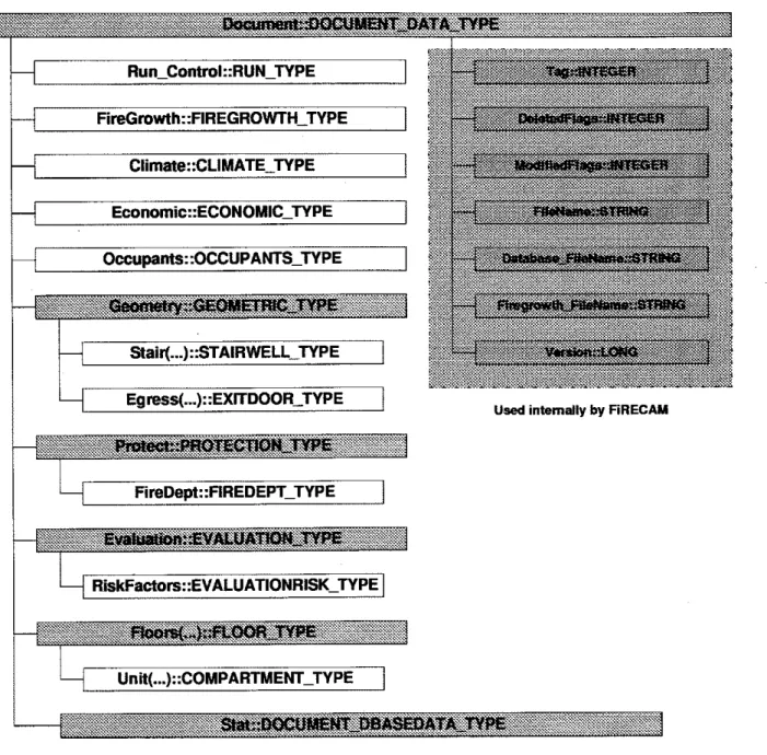
43Major structural elements of the Document :: DOCUMENT-DATA-TYPE
...
data structure 45 Contents of RunContro1::RUN-TYPE data section...
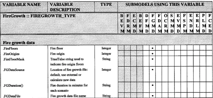
47Contents of FireGrowth::FIREGROWTH-TYPE data section
...
48Contents of Geomeby::GEOMETRIC-TYPE data section
...
49Contents of Geometry.StairO..STAIRWELL-TYPE data section
...
50Contents of Geometry.EgressO..EXITDOOR-TYPE data section
...
50Contents of Protect::PROTECTION_TYPE data section
...
51Contents of Protect.FireDept..FIREDEPT-TYPE data section
...
54Contents of 0ccupants::OCCWANT-TYPE data section
...
55Contents of Eva1uation::EVALUATION-TYPE data section
...
56Contents of Evaluation.RiskFactors::EVALUATIONRISKKTYF'E data section
...
56Contents of Economic::ECONOMIC-TYPE data section
...
57Contents of C1imate::CLIMATE-TYPE data section
...
57Contents of Floor0::FLOOR-TYPE data section
...
58...
Contents of FloorO.Unit()..COMPARTMENT-TYPE data section 60 Major structural elements of the Stat::DOCUMENT-DBASEDATA-TYPE...
data structure 61 Contents of DeptStatistics::FDSTATISTICS-TYPE data section...
63...
Contents of FireStatistics::FIRESTATISTICS-TYPE data section 65...
Contents of OccptStatistics::OCCPTSTATISTICSSTYPE data section 66 Contents of Statistics::STATISTICSSTYPE data section...
67Contents of Numerical::NUMERICAL~TYPE data section
...
68Contents of Costs::COST-TYPE data section ... 69
Contents of Costs.DefaultCost-ConstrO..COST-BASIC-TYPE data section .... 70
Contents of Costs.DefaultCost-Pwsive0::COST-PASSIVE-TYPE data
...
section 71 FiRECAMrM output database . Primary and secondary tables...
73Database table field contents for Building Evaluation Model (BEVM) p r i m q table
...
75Database table field contents for Fire Department Response Model (FDRM) primary and secondary tables
...
76...
Database table field contents for Economic Model (ECMD) primary table 77...
Database table field contents for Design Fire Model (DFMD) primary table 77 Database table field contents for Fire Growth Model (FGMD) primary and secondarytables...
79Table 6-7. Table 6-8. Table 6-9. Table 6-10. Table 6-1 1. Table 6-12. Table 6-13. Table 6-14. Table 6-15.
Database table field contents for Occupant Response Model (OCRM) primary and secondary tables
...
81 Database table field contents for Smoke Movement Model (SMMD) primary and secondary tables...
83 Database table field contents for Evacuation Model (EVMD) primary andsecondary tables
...
84 Database table field contents for Fire Spread Model (FSPM) priumy andsecondary tables
...
86 Database table field contents for Expected Number Of Deaths Model (ENDM) primary table... ... ... ... ... ... ... ...
....
....... . ....
88 Database table field contents for Expected Risk To Life Model (ERLM)primary table
...
89 Database table field contents for Property Loss Model (PLMD) primary table....
90 Database table field contents for Fire Cost Expectation Model (FCED)primary table
...
90 FiRECAMTM output database - SQL queries...
911.1 F i C A P Description
FiRECAMTM E i c Risk Evaluation and Cost Asscssmcnt Modcl) is a computer model that is being developed at the National Rcscarch Council of Canada. Thc modcl can be used to assess both-fue ris& to life and protection costs and expected losses in a building. A general description of the model has been published previously [I]. This report describes the interaction
and data flow among the individual models of F i R E C W .
In its c w n t implementation, FiRECAMTM is a standard Microsoft windowsm compatible graphical user interface (GUI) software package making use of a mouse, pull-down menus and
aaiogue boxes. - -
The software was developed using standard commercial program development tools and laneuaee libraries. For this release. F i R E C W was coded using commerciallv-available gaihi&l interface software to handle the user input and reportini tasks.
.
F i R E C M M uses six design fires in the compartment of fire origin, and the subsequent fire and smoke spread, to cvaluate life risks and protection costs for apartment and office buildings. Thc six design fircs, representing the wide spectrum of possible firc types, arc:
1. Smouldering fue with the fire compartment entrance door open, 2. Smouldering fire with the fire compartment entrance door closed,
3. Flaming non-flashover fire with the fire compartment entrance door open, 4. Flaming non-flashover fue with the fire compartment entrance door closed, 5. Flashover fire with the fire compartment entrance door open,
6 . Flashover fire with the fire compartment entrance door closed.
The probability of occurrence of each design fire, given that a fire has occurred, is based on statistical data. For example, in Canada, statistics show that 24% of all office fires reach flashover and become fully-developed fires, 54% are flaming f m s that do not reach flashover and the remaining 22% are smouldering fires that do not reach the flaming stage [2]. If sprinklers are installed, the model assumes that some of the flashover and non-flashover fires, depending on the reliability and effectiveness of the sprinkler system, are rendered non-lethal[3].
F i R E C W evaluates the cumulative effect of all probable fire scenarios that could occur in the building during the life of the building. For example, in an office building, a fire scenario could be one resulting from one design fire in any one of the floors in the building. The number of fire scenarios, therefore, is the product of the number of design fires and the number of floors in the building.
In the case of an apartment building, the scenarios with occupants awake and occupants asleep are treated separately.
F i R E C W consists of a number of submodels that simulate the dynamic interaction of fire growth, smoke spread, occupant response and fue department intervention. For each fire scenario, the model calculates the expected number of deaths and fire losses. These values are then combined at the end with the probabilities of occurrence for the fire scenarios to obtain the following two decision-making parameters:
1. Expected Risk to Life (ERL), defined as the expected number of deaths over the design life of a building, divided by the population of the building and the design life of the building.
2. Fire Cost Expectation (FCE), defined as the expected total fire cost which includes the capital costs of the passive and active fire protection systems, the maintenance cost of the active fire protection systems and the expected losses as a result of all probable fire spread in the building.
1.2 Computer System Requirements
The present release of FiRECAMTM requires the following system configuration: 80286 or newer CPU running Microsoft windowsa 3.1 or newer.
8 to 16 MB of RAM (16 MI3 recommended). Hard disk with approximately 15 MB free space.
Math coprocessor strongly recommended fo& 286 and 386 CPU. Mouse compatible with Microsoft Windows .
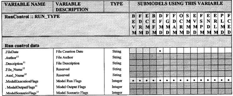
2. F i R E C m MODELS
This section gives a brief description of the individual FiRECAMm models and their linkages; e.g., interaction with the other models of FiRECAMTM.
FiRECAMm consists of fifteen interconnected models. The results of each model are stored in temporary files which are then used by other models to compute their respective outputs.
Table 2-1 lists the models used in FiRECAMTM and their purposes.
2.1 Model Naming Convention
In this document, frequent references will be made to the abbreviated names of the individual F i R E C . W models. For reference, Table 2-1 below lists the description of a model, and its abbreviation. These model short names are used to derive the base names of any
temporary files produced by each model, and any sections of the final output databases. Table 2-1. F i C A M T M model description and abbreviations
artment as well as the
and contents costs, as well as osts for passive and active fire
otection and suppression
Table 2-1. F i C A i W M model description and abbreviations (Cont.)
throughout the building as a
function of time. In addition, this model computes the critical time that the stairs cannot be used by the occupants to
building, given a floor of fire origin, building population and
Element Failure
structure and contents givm fire and smoke spread, and
2.2 Model Temporary Fie Naming Convention
During its execution, FiRECAMTM creates and uses temporary files to pass parameters and data between its individual models. When a model creates a temporary file, it uses the following naming convention:
$ $ $ $ [ m o d e l n a m e ] . [ l t o 3 d i g i t extension i n d i c a t i n g f i l e
#I
A prefix consisting of four dollar signs; i.e.
'
$$$$ ' is followed by a four-letter model name. The file extension indicates the number of the file; it is used to distinguish multiple temporary files created by the same model. For example:The Fire Growth Model (FGMD) creates two temporary files:
The first file is named $$$$FGMD.O for file # 0
The second file is named $ $ $ $ FGND. 1 for file # 1 The Smoke Movement Model (SMMD) also creates two temporary files:
The first file is named $$$$S=. 0 for file # 0 The second file is named $$$$S=. 1 for file # 1
The Design Fire Model (DFMD) creates a single temporary file:
Its file is named $$$$DFMD.O for file # 0
FiRECAMTM uses a zero-based file numbering convention. The first temporary file required by a model is numbered 0 , The second file is numbered 1, and so on.
2.3 Location of Temporary Files
By default, F i R E C W creates all temporary files in the Windows TEMP directory'. F i R E C W does allow the user to specify the program's main directoly as an alternative. All temporary files are deleted at the end of a FiRECAMTM run.
An available user option allows F i R E C P to create a dsbugging dump file that will contain all the contents of the temporary files created during a run
.
2.4 Temporary F i e Contents and Struchve
All temporary files created by F i R E C W are written out as ASCII text files, in a table (rows and columns) format. The general structure of a temporary file is as follows:
'
'lhe Windows TEMP &rectory is a specla1 disk subhrtxtory uscd by Windows for storing its (and 11s dpplicat~om') temporary files. Hy convention, any Windows program (such as FiRECAMm) us- [his directory. It is usually set by an environment variable callcd TEMP In the syst~m's $tanup files (AUTOI*:XEC.BAT and CONFIG.SYS). For more information, pleasc consult Microsoft Windows documeniatioo.'
At the end of cach scenario, FiRECAM'U will scan all the temporary files crcatud by wch model, and concatenate the contents into a single dump file.Table 2-2. F i C W general temporary file layout
For example, The Building Evaluation Model (BEVM) produces a single data column output file as shown below:
and a multiple-column data file is created by the Smoke Movement Model (SMMD).
2.5 Model Execution and Linkage
FiRECAMTM executes its models, in a predetermined order, so models requiring data from previous models will have these results available as needed. The order in which the F i R E C W models execute during a run is dictated by the following conditions:
Some models are fire scenario (and fire origin floor) independene. Therefore, they may be executed once per F i R E C M M run to reduce computation time. If such models are also model independent, they can also run at the beginning of F i R E C W and create a single c o ~ v of their respective temporaw files. E x m l e s of such models are BEVM, FDRM, and
EC-. A
-
Some models execute on a per fire scenario basis only. For example, PGMD runs once per fire scenario only. The results of this model are then stored in its temporary files.
Some models execute on a per fire scenario basis, but may internally generate calculations for a fire occurring on each floor of the building. For example, SMMD will compute the smoke
'
Here, model independent means no other models are required to run in order to produce intermediate results thathazard data throughout the building for a fire occurring on Floor 1, then on Floor 2, and so forth. These results are then stored on a per floor basis for each fire origin floor.
Table 2-1 lists the scenarios and occupant states for which each F i R E C W executes.
Table 2-1. FiRECAiWM model scenario execution list
C -Flashover fue, fxe origin compartment door
- Non-flashover fire, fue origin compartment NFDC - Non-flashover fue, fire origin compartment SMDO - Smouldering fxe, fire origin compartment SMDC - Smouldering fie, fire origin compartment
Figure 2-1 shows the actual order of model execution. Independent models are run only once at the beginning to conserve computation time, and the Design Fire Model
(DFMD)
executes as the first of the scenario dependent models. DFMD then produces the fire occurrence probability results used by other models whose calculations are then used by other models. At the end of all the fire scenarios' calculations, two small models, ERLM and FCED, calculate the final results of the run.Figure 2-2 shows the order in which F i R E C W executes each of its models, but also shows the order of the tempomy files created by each model. The arrows represent the data
linkages and flow between the models. In general, the models at the end of the execution order use intermediate results of previous models. For example, the Expected Risk to Life Model
(ElUM) requires data from the Expected Number of Deaths Model (ENDM) and the Design Fire Model
(DFMD).
It then produces a final expected risk to life report.Some lncldcls are x m r i o independent, therefore their output IS computed once only.
For office occuoancv buildings, occuvams arc always assumcd to be awake tx.uupants a i l c ~ sc~nario is nor run.
+ Data Flow Direction
OPTlONAL SUBMODELS
1
DFMDI
I
FGMD1
1
OCRM1
I
ENDMI
FINAL REPORTSLegend Models Run Once
0 Models Run far each Scenario
t Data Flow Diredon Input to Model Output from Mcdel
FDRM.0' Fire Depadmnt Setup-
and Response Times
BEVM 0' Bd 0 1 9 Evdualno m n sk tactom ECMD.0' Structural. Pmtectia, an Maintenance Costs
Fire SceMrio Pmbabilies a Fire Occur- Rates
Fire Cue and Sensor
Cancentradons vs. li Ahation Times
7
ERLM.0' Scenario Expect
Risk to Life
This section of the report will describe the individual FiRECAMTM models.
3.1 BEVM
-
Building Evaluation ModelThis is an optional model that can be run to evaluate the fire characteristics of a building if the building is considered to be not a typical building where normal fire statistics can be applied. Based on the types and quantity of combustibles in the building and the separation of the combustibles from potential ignition sources and the maintenance of fire suppression systems (if they are installed), the model calculates the factors that can be used to correct the statistical values of the probability of fire starts, the probability of various design fires that may develop and the reliability of the fire suppression systems. These factors are used later in the Design Fire Model (DFMD) to correct the normal statistical values.
Main input Objectives
I
I
Building layoutThis model evaluates the fire characteristics of a building.
~nstalled systems
Building management and occupant cbaractaistics
Building fuel sources, quantities and flammability information Building risk of explosion and risk of collapse factors
Construction materials Contents characteristics
Comments Main output
Rate of fire occurrence
Probability of flashover fire occurrence Probability of non-flashover fire occurrence
.
Probability of smouldering fue occurrence Probability of manual suppression Probability of automatic suppression Probability of barrier failureFactors which are used to adjust the following probabilities, computed by the Design Fire Model (DFMD).
This model is executed once at the beginning of FiRECAMTM.
The temporaq output file(s) for this model are created once, and used throughout the execution of F i R E C M M . The files are then deleted at the end of a F i R E C W run.
10
Table 3-1. Contents of Building Evaluation Model (BEVM) file #O
Citing 3-1. Example output file: BEVM.0
W r y of &hover Jim
Factor used to adjust pobabhty of non- flashover fire
Factor used to adjust pmhhllty of smuldenng fue Factor used to adlust pb&lrfy o f b m e r fiulure
Factor used to a w t probabl1,ty of m n a l
mpFBess10n
Factor used to adjust p b a b h i y of m m c syPpTeSs,on BEVM 0 BEVM 0 BEVMO BEVMO BEVM.0 NonflFrreFacfor SmldrFlreFactor BmFdFactor S q x W a c t o r SuPp~AuIFastor Slngle Slngle Slngle Smgle Slngle - - - 3 4 5 6 7 2 2 2 2 2 DFMD DFMD Not Used Not Used Not Used
This is an optional model that evaluates the fire department response characteristics to a building where normal response statistics can not be applied. Considering the characteristics of the fire department and the distance to the building, the model calculates the response time to the building. The computed response time is used later in the Fire Department Action Model
(FDAM) instead of the normal statistical value.
Objeclives Methodology
This model calculates the response of a fire department to a fire site
The response time is computed by adding the dispatch, preparation and setup time
Main input Fire department characteristics
Distance between the fire department and the building
I
The temporary output file(s) for this model are created once, and used throughout the execution of F i R E C W . The files are then deleted at the end of a F i R E C W
run.
Main output I
Table 3-2. Contents of F i e Department Response Model (FDRM) file #O Fire department response and setup time
Comments This model is executed once at the beginning of FiCAMT".
Tun. of fire department have1
Tun. of fir. department
setup Tlme o f f i ~ department respan= FDRMO FDRM.0 FDRUO Travel Tune SeNpTm ResponseTw Slngie S d e S d e ses ses s e ~ 3 4 5 2 2 2 FDAM FDAM
This model calculates the building construction cost and the capital and maintenance costs of the fire protection systems. It also calculates the replacement costs of building contents and the restoraiion costs of building elements as a result of smoke, fire and water damage. These costs are used later in the Property Loss Model (PLMD) to calculate the expected fire losses for each fire scenario, and in the Fire Cost Expectdon Model (FCED) to calculate the total fire cost expectation.
Objectives
r
This model calculate the capital costs of shuctural building components and fire protection systems. In addition, It also calculates the annual costs of replacement, maintenance, and organizational activitiesthe building (including structural components, fire protection systems, and
organizational systems), as well as maintenance and organizational activities
I
IMain input Methodology
Main output
This model retrieves cost data from the costs database by using the building layout and types of fire protection systems installed. It then sums the costs of components in
I Comments
Building layout
Itanized capital and annual costs of components and activities
Alarm and detection system characteristics Fire suppression system characteristics Passive system characteristics
Smoke control system characteristics
Emergency & organizational system characteristics Economic factors
p~
Total capital cost per floor Total annual cost per floor Basic construction cost per floor FRR incremental cost per floor Construction cost per floor Annual maintenance costs Annual organizational costs Annual replacement costs
Present worth of total annual costs Active protection systems capital costs Detection and alarm system capital costs Automatic suppression system capital costs Manual suppression system capital costs Smoke control system capital costs Emergency system capital costs Organizational system capital costs Capital cost of compartment of fire origin Capital cost of floor of fire origin
Capital cost of each of the other floors
'Ibis model is executed once at the beginning of FiRECAMfM.
The temporary output file(s) for this model are created once, and used throughout the execution of F i R E C M M . The files are then deleted at the end of a F i R E C M M
14
Table 3-3. Contents of Economic Model (ECMD) file #O
Listing 3-3. Example output file: ECMD.0
excl"'Jmg comparmlent
'
Nis used to indicate the fire origin floor number. of fire anpnBaste aruchue capital
costfn.ermrenom
Captal cost far fire pot=- sy-
Annual cmt for fire pmtcchrn systems ECMDO ECMDO ECMDO B a s ~ c S r m c ~ o s t O E N CapcOaProfeehanN AnnlCwtPmteFbd Slngle Smgle S ~ l e $ $ 6 3 4 5 2 2 2 PLMD PLMD PLMD
This model calculates the probability of failure of the boundruy elements (such as walls, floors and doors) in the building when exposed to a design flashover fire that could occur in the building. The characteristics of the design flashover fire are obtained from the Fire Growth Model
(FGMD). The failure probability values are used later in the Fire Spread Model (FSPM) to calculate the probability of fue spread from the compartment of fire origin to every location in the building. Objectives Methodology Main input Mnin output Comments
This model calculates the probability of failure of boundary elements of construction when these boundaries are subjected to fully developed fues.
This model is based on the normalized heat load concept.
It compares the heat attack in the fire resistance rating test on the boundary element with the heat attack in a real fire to estimate the probability of failure of the element. The heat attack in real fues is computed based on the fue load, the area of the compartment and the ventilation openings.
Fire Resistance rating of the boundary elements Type of construction
Fire load in building Building geomehy
Probability of failure of boundary elements.
This model is executed once at the beginning of F i R E C A F .
The temporary output file(s) for this model are created once, and used throughout the execution of FiRECAM. The files are then deleted at the end of a F i R E C W run.
16
3.5 DFMD
-
Design Fire ModelThis model calculates the probability of a fire scenario occurrence. The six fire scenarios, representing the spectrum of possible fire types, are:
Smouldering fire with the fire compartment entrance door open, a Smouldering fire with the fire compartment entrance door closed,
a Flaming non-flashover fire with the fire compartment entrance door open, a Flaming non-flashover fue with the fire compartment entrance door closed,
Flashover fire with the fire compartment entrance door open,
a Flashover fire with the fire compartment entrance door closed.
The probability of occurrence of each design fue, given that a fire has occurred, is based on statistical data. If sprinklers are installed, the model assumes that some of the flashover and non-flashover fires, depending on the reliability and effectiveness of the sprinkler system, are rendered non-lethal.
Flashover Non-flashover Smouldering
Objectives This model computes the rates of fire occurrences, and the probabilities of the fie types being one of the following:
F i e occurrence and probabilities are adjusted by the output of the Building Evaluation Model (BEVM).
Methodology
If sprinklers are installed, flashover and non-flashover occurrence probabilities are adjusted downward to reflect the probability of suppression by the sprinklers. Fire occurrence and type probabilities are read from the Statistics section of the Expert Data Input, which are obtained from studies.
I
Main output
(
Adjusted rates of fue occurrences and probabilities of fire type: Main inputRate of fire occurrence
Probability of flashover fire occurrence Probability of non-flashover fire occurrence Probability of smouldering fue occurrence
Statistical values for fire occurrences and probabilities of fire type
Building Evaluation fire rate and occurrence factors Presence of sprinkler systems in building
The temporary output fde(s) for this model are created at the beginning of this
model's execution. Files existing from previous scenarios are overwritten.
I
I
Table 3-5. Contents of Design F i e Model (DFMD) file #O
Listing 3-5. Example output file: DFMD.0
n o ~ 8 a s h ( 1 ~ ~ f u P s
Rok&hly of
mnuldenag fires
Adlusted rate of fm occunence for aparLment b"~I&ngs for occupants
awalreorasleep DFMDO DFMDO ~ W M PMFueStartRate Slngle Slngle - - PLMD ERLM PLMD kRLM PLMD
3.6 FGMD
-
F i e Growth ModelThe fire growth model predicts the development of the six design fires in the compartment of fire origin. Details of the f r e growth model for apartment buildings are described in a previous paper [4]. The model calculates the burning rate, room temperature and the production and concentration of toxic gases as a function of time. With these calculations, the model determines the time of occurrence of five important events:
Time of fire cue,
Time of smoke detector activation,
Time of heat detector or sprinkler activation, Time of fire flashover,
Time of fire burnout.
The first three detection times are used later in the Occupant Response Model (OCRM) and Evacuation Model (EVMD) to calculate the response and evacuation of the occupants from the building. The flashover time is used in the Fire Department Action Model P A M ) to calculate the effectiveness of fire fighting and rescue efforts. The burnout time is used in the Smoke Movement Model (SMMD) to calculate the maximum smoke hazard that the occupants could be subjected to. The model also calculates the mass flow rate, the temperature and the concentrations of CO and COz in the hot gases leaving the fire compartment. This latter
information is used in the Smoke Movement Model to calculate the spread of smoke to different parts of the building as a function of time.
Objectives
Methodology
Main input
Main output
Comments
This model calculates the fire development in the compartment of fire origin. The model then computes the temperature, CO and COZ concentration with time in that compartment as well as the flow of hot gases out of the compartment.
Determines the timing occurrence of the different states of the fire development process.
This model is a one zone model.
Fire growth is computed based on the combustion of a representative fuel: Polyurethane foam for residential buildings
Wood cribs for office building8
Compartment dimensions, fire load and openings Type of design fue
Tesnperature, CO, COz and mass flow rate of hot gases leaving the compartment of fire.
Times of occurrence of a number of states of fire growth This model is executed for each fue scenario in FiRECAiW".
The tunporary output file(s) for this model are created at the begmning of this
Table 3-6. Contents of F i e Growth Model (FGMD) file #O - Dewiption Time of mivation of
I
) S h g l e /=
1 3 21
T i m of aRiva6on of smoke alarmFire Cle %es
File Name and Number FGMD.0 Time of flashover Time of burnout ?*e'-&&im* . . . . . . .. . . . . . . . . . .
Be-ng of tim frame 1
Beginning of time frame 2
Beginning of tim frame 3
mnningoftimefmne5
I
FGMD.0I
BeginTimeF-5I
S i eI
secVariable Tag Namc
B e a n g of time frame 4
1 I I I
Beginniogofdmpframe6 FGMD.0 W T i r n e F d Single sec
TimeActivateSmoke Alarm FGMD.0 FGMD.0 <::;::,:;:;i;'::..:j:.;.;;::::' . . . . . . .. . .. . , , . , FGMD.0 FGMD.0 FGMD.0
Begin oftuneframe7 FGMD.0 BeginTimeF-7 Single sec
FGMD.0
+I
SMMD Data 'QPe Single T i F h h o v e r TmeBumout , : :. . . :,; .:<;:::: .. . . .. . . . , :i: : : BeginTimeFramel Be@TmeFrameZ BqhTLneF-3 Units Row BeginTimeFme4 ss: Single Single :i:,:.:'~.' . .:..:. . . Single S i i e Single -oftimPfrar.P9 Beginning of h e frame 10 Cd Siogle Modele Usiag This Owpet 2 see s : . : : .,;::.:::;:: ;.:; .. . . . . . , wc sec wc FGMD.0 FGMD.0 set 2 4 5 :j::.ii.: . . . . :::I<:;I , , 6 7 8 BsgkTimeframe9 BeginTimeF-10 EVMD FDAM EVMD 1 2 2 :j/:;:;;.::...;: .. . . 2 2 2 9 Single Single FDAM EVMD FDAM SMMD ::!$;: .;..:.: .. . . . . :,;:;::::; ??.? .;:;: ;:;; .:::.; . . . RlAM SMMD EVMD FDAM SMMD EVMD FDAM SMMD EVMD 2 sac s e ~ R ~ A M SMMD EVMD 14 15 2 2 FDAM SMMD EVMD FDAM SMMD EVMDTable 3-7. Contents of F i e Growth Model (PGMD) file #I
Listing 3-6. Example output me: FGMD.0
This model calculates the effectiveness of fue fighting and rescue efforts, based on the time of arrival of the fue department, the time of flashover from the Fire Growth Model (FGMD) and the fue fighting resources that have arrived at the scene. The rescue effectiveness value is used later in the Evacuation Model (EVMD) to reduce the number of occupants who are trapped in the building and the fire fighting effectiveness in the Fire Spread Model (FSPM) to reduce the probability of fire spread. The time of anival is also used later in the Smoke Movement Model (SMMD) to evaluate the smoke hazard conditions to the occupants at the time of arrival of the fire department.
Methodology Objectives
It also calculates the impact of fue department action on the fire spread and smoke hazard probabilities in the building as well as the rescue effort.
Uses the probabilities of fire detection at the different states of fire development and probabilities of calling the fire department at those states to find the overall
probability of notification. The probability of notification is assumed to be equal to the probability of arrival.
This model calculates the probability of fire department arrival at the fire site and the expected time of tire department action.
The expected time of action is computed by adding the notification time, the response time, the travel time and the setup time.
The impact on the fire spread and smoke hazard probabilities is computed using the f ~ e fighting effectiveness probabilities computed by the firefighters effectiveness model.
The temporary output file($ for this model are created at the beginning of this model's execution. Files existing from previous scenarios are overwritten. Main input
Main output
Comments
Notification, response and setup times of the fire department Probability of calling fire department by building occupants Direct connection to fire department
Probability of fire department amval Expected time of arrival
Fire fighting effectiveness in tarns of intervention and extinguishment probabilities Rescue effectiveness
24
Table 3-8. Contents of P i e Department Action Model (FDAM) file #O
mierveennon Pmhbhly of fire deplment ~ n w e n n o n Combtned pmtarbrlrlyaf fire departmeat exbng"hCent Resweffestveness of
the fire depturment
FDAMO FDAMO FDAM.0 RobIntervenUon p r o b ~ s h Re-EffectFacto~ Sm@e slnde Single - - 3 4 5 2 2 2 FSPM S M M D FSPM ENDM FSPM ENDM
Table 3-9. Contents of F i e Department Action Model (FDAM) file #I
Scenario is one of the following: FL/DO, FLLDC, NFIDO, NF/DC, SMIDO, SMIDC
d e p m m i lnfwenhon f o r f l m e h l Pmbabdtttes of fire deparrment ~ntenenhon for tlmeframe2 h W l t t e s of fire -nt mnlemnhon for flmefiamp3 Pmbabnlthes of fire d e p i m n t mlemenhon for turnframe4 Pmb&hhes offire dqaimsnt ~ntmenhon forameframe5 Pmbd-el~hes of fire deparmgat mtenentlon foromeframe6 Pmbabdthes of iire deparrmeat mtnvenhon for turnframp7 Fmbabzlthes of fire d q m m u lntervenuon for turnframe8 hbabnhhes of fire -nt lntmenUon for flmefiame9 hbabdlues of fire -nt mteervenaon for omeframp10 FD.4M.l FDM 1 FDMI FDAMI FDAMl FDAUI FDAM1 FDAM I FdIatervPmbsScenmoT m r F d Fdlnte~PmbsSeenorzoT wF-3 FdIatewPmbScenanoT UneFranld FdIatenrPmbsScenanoT - F d FdlntewPmbsScenarroT -Frame6 FdJnt-PmbsScenmroT lllgFmns7 FdIatewRobsScenmoT -F& FdIntewRobsScenonoT -Frame9 FdJntenProbsScenartoT -Frame10 S&e Slngle Slngle Smgle Slngle Smde Slngle Slngle Smde - - - - - - - 2 3 4 5 6 7 8 9 10 2 2 2 2 2 2 2 2 2 OCRM OCRM OCRM OCRM OCRM OCRM OCRM OCRM OCRM
Listing 3-8. Example output file: FDAM.0
This model calculates the probability of occupant response at different locations in the building and at the 3 detection times (fire cue, smoke detector, heat detector/sprinkler activation). Details of this model are described in a previous publication [5]. The probability of response is calculated based on warnings received from fire cues, local alarms, central alarms, voice alarms, warnings from others and from fire fighters. The response probability values are used later in the Evacuation Model (EVMD) to calculate the percentage of the occupants who would respond and evacuate at the ten different time frames.
Objectives Methodology Main input
Main output
Comments
This model calculates the probability building occupants will decide to evacuate the building.
The response probabilities are calculated from the probabilities of detection and fire cues at ten time frames.
Building layout and installed protection systems Installed protection system components
Protection system sensor activation probabilities and reliability Occupant perception probabilities for ten time frames
Occupant action probabilities for ten time frames
Occupant response and evacuation probabilities for ten time frames Probabilities of no occupant response
Probability of manual suppression by occupants
This model is executed for each fire scenario in FiRECM".
The temporary output file(s) for this model are created at the beginning of this model's execution. Files existing from previous scenarios are ovenwitten.
Table 3-10. Contents of Occupant Response Model (0CR.M) file #O - mCFTimeFrame2 oOCFTimeFrame4 oOCFTimeFrame5 Conditional evacuation oOCFTimeFrame6 oOCFTimeFrame6
Table 3-10. Contents of Occupant Response Model (OCRM) 6le #O (Cont.)
(
occuyats ea h v e i of Fire (OLQ Conditional e v d o nprobabitity for time fialm1
pmbability for time
h 7
I
LFTimeFrameZ
Conditional evacuation
probabiiiiy for thz oOLFTimeFrame3
OCRM.0
probability for time
h 5
Conditional w d o n probability for time frame6
Conditional e v d o n
Conditional w d o n probability for time
b 8
Conditional evafnafian probability for time frame9 ProbEvacScenari o ~ ~ ~ ~ i m e ~ r a m e l ' 0CRM.O 0CRM.O I I I I I I I OCRM.0 OCRM.0 Single oOLFTimeFrame5 ProbEvacScenari oOLFTimeFrame6 ProbEvacScenari ProbEvacscenari oOLFTimeFrame6 ProbhracSc~ari oOLFTimeFrame6 2 20 - Single S i i e EVMD ENDM - Single S i e Single Conditional wmatlon probability far time
I I - - - - OCRM.0 2 16 17 Probhracscenari oOLFTimeFrame6 EWm 18 19 2 2 EVMD ENDM EVMD 2 2 EVMD ENDM EVMD ENDM
30
Table 3-10. Contents of Occupant Response Model (OCRM) file #O (Cont.)
probability for time
probability for time
C o n d i t i d evacuation probability for time f,=nle4
Conditional evacuation pm-ty for time
&,me5
Conditional evacuafion probability for time
6ant=6
ComditiWal e v ~ i o n
+ility for fime
b 7
Conditional - d o n +ility for time
frame8
Conditional w-tion
probability for dme f,=nle9
Conditional e v d o n pmbsbility for time
frame 10 . .. .. . . . : . . .,S* . ... . :mi&imfin SmonlGng fire .~pp....ion probability OCRM.0 OCRM.0 0 C R M . O 0CRM.O 0CRM.O WRM.0 oCRM.0
*
oCRM.0 oOOLTimeFrame3 P r o b E v a c s c e n a r i oOOLTimeFrame4 P r o b E v a c s c e n a r i mOLTimeFrame5 P r o b E v a c S c e n a r i oOOLTimeFrame6 P r o b E v a c s c e n a r i oOOLTimeFrame6 P r o b E v a c S c e n a r i oOOLTimeFrame6 P r o b E v a c S c e n a r i oOOLTimeFrame6 P r o b E v a c s c M a r i oOOLTimeFrame6*,,-
w-:,;
::,; T o t a l P s M F s U B p r s c ~ a r i o S i e W e Single Single Single Sic S i i e ... Single - - - - - ... - 24 25 26 27 28 29 30 :.:., 3 1 2 2 2 2 2 2 2 : 2 S M M D W M D S M M D EVMD SMMD W M D S M M D EVMD S M M D EVMD S M M D EVMD SMMD EVMD . .. ::;';;::;::;:;::,;'.:.,;:~;.:{,::~:~,;,:.:.:.' SMMD3.9 SMMD
-
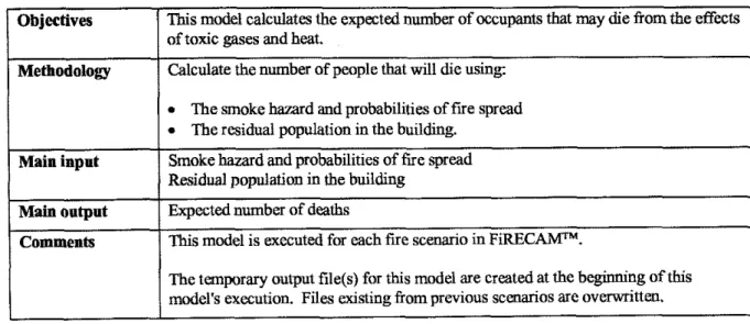
Smoke Movement ModelThe smoke movement model calculates the spread of smoke and toxic gases to different parts of the building as a function of time. Details of this model are described in a previous publication [6]. The model also calculates the critical time that the stairs become untenable. This is the time that the remaining occupants, who have not evacuated the building, cannot use the stairs to evacuate and are considered wapped in the building. This critical time is used later in the Evacuation Model to calculate the time available for evacuation.
This model also calculates the smoke hazard (probability of incapacitation due to toxic gases) at every location in the building at the time of arrival of the fire department, obtained from the Fire Department Action Model (FDAM). If there is no fire department response, this model calculates the smoke hazard at the time of burnout in the compartment of fire origin, obtained from the Fire Growth Model (FGM1)). The smoke hazard is based on the dosage and
temperature of the toxic gases that the occupants are exposed to. The smoke hazard values are used later in the Expected Number of Deaths Model (ENDM) to evaluate the expected number of deaths at every location in the building, and in the Property Loss Model (PLMD) to evaluate the replacement costs of building contents due to smoke damage.
Objectives
Methodology
Main input
Main output Comments
This model calculates movement of hot gases from the compartment of fire origin to other locations in the building.
Determines temperature, CO and C02 concentrations in the building with time.
Computes the smoke hazard probabilities in the building based on the concentrations of CO and C02 and temperature at different locations in the building.
Estimates time that the stairs become critical and occupants cannot use them for evacuation. Use buoyancy and stack effect forces to compute movement of hot gases from the fire compartment to other locations in the building with time.
From mass, energy and species conservation equations find the temperature and CO and C02 concentrations at every location with time.
All compartments on each floor, other tban the compartment of fire origin, are grouped into one compartment.
The FID values are computed using StecWer's equations [6].
The critical time when the stairs become critical is computed based on the effect of temperature and toxic gases on occupants from the top floor leaving through the stairs. Smoke hazard probabilities are computed using the concentrations of toxic gases and the temperature rise in the building. These are computed at two reference times; the time of fire brigade arrival and the burnout time. These include hazard from toxic gases (FID) and hazard from temperature.
Building geometric dimensions Number of compartments per floor
Flow and properties of hot gases from the fire compartment Probabilities of smoke hazard
T i e that stairs become critical
This model is executed for each fire scenario in FiRECAW".
The temporary output file(@ for this model are created at the beginning of this model's execution. Files existing from previous scenarios are ovmitten.
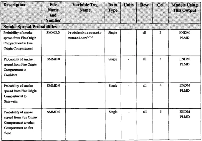
Table 3-11. Contents of Smoke Spread Model (SMMD) file #O
spread fmm Fire Origin
C a m tto Fire
I
Origin COnpWmeat Pmbabikty of smoke s p d fmm F b OriMn Co-to - Fmbability of smoke qxed l k n Fire %ginCa,qrbrent to Srairwdls
Table 3-12. Contents of Smoke Spread Model (SMMD) gle #1
SMMD.0
SMMD.0
F m W t y of m k e
spread h m Fire %pin
Ca-t to ofher
co,"&mmmt on fire floor
Listing 3-11. Example output Be: SMMD.0 SMMD.0
Single - dl 3 ENDM
This is a time-dependent, deterministic model that calculates the egress of the occupants from the building. Based on the probability of response at ten time frames computed by the Occupant Response Model (OCRM) and the critical time of the stairs from the Smoke
Movement Model (SMMD), the model calculates the number of occupants who can evacuate the building and those who are considered trapped in the building. The number of occupants who are trapped in the building is reduced by the effectiveness of the rescue efforts of the fire department. The residual population in every location of the building is used later in the Expected Number of Deaths Model @NDM) to calculate the expected number of deaths.
Objectives
The flow of occupants through the stairs is computed using empirically derived
occupant flow equations.
I
This model calculates the residual population in the building when the stairs become mitical and occupants cannot use them for evacuation.
Methodology The model canputas the movement of occupants through the stairs and out of the building. For this calculation it assumes a certain specified floor evacuation sequence.
Main input
Main output Comments
The time available for the occupants to evacuate is obtained from the F i e Growth Model (FGMD) and the Smoke Movement (SMMD) models.
Occupants who are unable to exit the building remain trapped inside the building and they are subjected to the probabilities of death at their location. These occupants are called the residual population.
Number of floors in the building
Number of occupants per floor in the building Number and dimensions of exit routes T i e available for occupant evacuation Condition of occupants, awake or asleep
Residual population in the building at the time that the stairs become critical. This model is executed for each fire scenario in FiRECAMFM.
The temporary output file($ for this model are created at the beginning of this model's execution. Files existing kom previous scenarios are overwritten.
Listing 3-13. Example output file: EVMD.0
PeoplejnFloorN Peopleinstairs Exitad
The Fire Spread Model (FSPM) calculates the probability of fire spread to every location in the building based on:
Probability of failure of the boundary elements obtained from the Boundary Element Failure Model @EFM), and
Fire fighting effectiveness obtained &om the Fire Department Action Model (FDAM).
The model is non-time-dependent where the probability of fire spread to every location in
a building is assumed to occur at the time of fire burnout in the compartment of fire origin. This is a conservative approach since fire spread to all locations in a building is usually a slow process; much slower than the time it takes for the fxe to bum out in the compartment of fire origin. The fire spread probability values are used later in the Expected Number of Deaths Model (ENDM) to evaluate the probability of life loss at every location in the building, and in the Property Loss Model (PLMD) to evaluate the replacement costs of building contents and restoration costs of building elements.
A recursive graph searching routine is used to find all the possible paths from a fire source location to other locations in the building, while computing their respective probabilities. Once all the possible routes are found, the probabilities are combined to yield a probability of fire spread from a source to a destination.
Objectives Methodology
This model computes the fire spread probabilities in the building based on the probabilities of barrier failures for each possible barrier and location.
This model represents the building compartments, corridors, stairwells and shafts as a directed graph. Corridors Stairwells Otbercompartments Main input Main output
I
I
for each floor, given that a fue occurs on a particular floor.I
All compartments on each floor other than the compartment of fire origin are grouped into one compartment.Building geometric dimensions
Barrier failure probabilities from BEFM
Probabilities of fue spread from the compartment of fire origin to:
Comments This model is executed for each fire scenario in FiRECAW".
The temporary output file@) for this model are created at the beginning of this model's execution. Files existing from previous scenarios are ovennitten.
38
Table 3-14. Contents of F i e Spread Model (PSPM) 6le #O
Listing
3-14. Example output file: BEVM.0Smgle - all 4 ENDM
M is used to indicate the affected floor number.
from Fire On- Compimsnt to
Starweus
Robab~I~g of k s p i d 6om Fare Ongm
C o q a m ~ n t to other Co-t on k
flmr
FSPUO mot Used) Slngle - dl 5
P L M D
E i D M
This model calculates the probability of life loss in every location in the building, based on the smoke hazard values obtained from the Smoke Movement Model (SMMD) and the fire
spread values obtained from the Fire Spread Model (FSPM). In this model, the probability of life loss is reduced if there is a refuge area nearby, such as a balcony, which the occupants can use to avoid the hazard. The model then calculates the expected number of deaths for the fire scenario being considered, based on the residual population obtained from the Evacuation Model (EVMD)
and the life loss probability values. The expected number of deaths is used in the Expected Risk to Life Model (ERLM) to calculate the total expected risk to life.
Table 3-15. Contents of Expected Number of Deaths Model (ENDM) file #O
Objectives Methodology
Main input Main output Comments
Listing 3-15. Example output me: ENDM.0
This model calculates the expected number of occupants that may die from the effects of toxic gases and heat.
Calculate the number of people that will die using: The smoke hazard and probabilities of fue spread The residual population in the building.
Smoke hazard and probabilities of lire spread Residual population in the building
Expected number of deaths
-
This model is executed for each fue scenario in FiRECAW".
The temporary output file(s) for this model are created at the beginning of this model's execution. Files existing from previous scenarios are overwritten.
3.13 ERLM
-
Expected Risk to Life ModelThis model calculates the overall expected risk to life (ERL) by using the expected number of deaths in the building for each fire scenario, obtained from the Expected Number of Deaths Model (ENDM), and the fue rates and probability of occurrence of each scenario,
obtained from the Design Fire Model (DFMD). The ERL is the expected number of deaths over the design life of a building, divided by the total population of the building and the design life of the building.
This model actually consists of two parts:
The first part calculates the Expected Risk to Life (Em%-) for a particular fire scenario. The expected risk values for each scenario are stored in a temporary file for further totalling by the second part of ERLM.
The second part calculates the total Expected Risk to Life (ERL) of a building at the end of FiRECAMlhl by reading the ERLsredD values for each scenario from the first part, and multiplying them by the probability of occurrence of the fire scenario in question. Finally, the sum of these ERL and scenario probabilities is the total ERL for the building; i.e.
ERL = E R L k , ~ o x P r o b ~ u n ~ i ~
Objectives
The expected number of deaths for each fire scenario Population of building
Rate of fire occurrences
(
.
The probabilities of occurrence of each scenario.This model calculates the expected risk-to-life for the building. The total risk to life
(Em) is the sum of all the expected risks for each lire scenario. I
Methodology
Building construction type Total population of building
Population for each floor in the building Expected number of deaths for each scenario Rate of fire occurrences
Calculates the expected risk-to-life for the building using
I Main input
Expected risk from each scenario from Part 1 Probabilities of each scenario occurring
I
I
ERLM Part 2: ERLM Part 1 :Main output
I
Expected risk-twlife.I
The second part of this model is executed once at the end of FiRECAhP', to calculate fmal expected risk results.
Comments The first part of this model is executed for each fire scenario to calculate a partial
Table 3-16. Contents of Expected Risk to Life Model (ERLM) file #O
3.14 PLMD
-
Property Loss ModelThis model calculates the replacement costs of building contents and restoration costs of building elements for the fire scenario being considered, based on smoke spread values from the Smoke Movement Model (SMMD), fire spread probabilities from the Fire Spread Model (FSPM) and replacement and restoration unit costs from the Economic Model (ECMD). The fire losses are used later in the Fire Cost Expectation Model ( X E D ) to calculate the total expected fire cost.
Objectives
Methodology
Main input
Main output
Comments
This model calculates the costs of heat, smoke, and water damage for a building structure and its contents. These costs are calculated for a specific scenario occurring on each floor of the specified building.
The probabilities of damage due to beat, smoke, and water are calculated for the type of fire sc&o (flashover, flaming, or smouldering fue). These are calculated for each level ofthe building design.
The total cost of damage due to smoke and fire is evaluated for each of the three fire types. This is done by multiplying these probabilities by the costs of the structure and the contents, and summing over each location and over each damage type,
Scenario characteristics Building layout characteristics
Shuctural and building system capital costs kom the Economic Model (ECMD) Value of contents
Sensitivity of building structure and contents to smoke and water. Smoke spread probabilities from the Smoke Movement Model (SMMD) Fire spread probabilities from the Fire Spread Model (FSPM)
Loss to structural components for occurrence of each fire scenario Loss to contents for occurrence of each f ~ e scenario
This model is executed for each fire scenario in FiRECAW".
The tempormy output file@) for this model are created at the beginning of this model's execution. Files existing from previous scenarios are overwritten.
Table 3-17. Contents of Property Loss Model (PLMD) tile #O
3.15 FCED
-
P i e Cost Expectation ModelThis model calculates the total fire cost expectation (FCE) by using the capital and maintenance costs for the fire protection systems, obtained from the Economic Model @CMD),
the expected fire losses for each fire scenario, obtained from the Property Loss Model (PLMD)
and the probability of occurrence of each scenario, obtained from the Design Fire Model
(DFMD). FCE is the expected total fire cost which includes the capital cost for the passive and active fire protection systems, the maintenance costs for the active fire protection systems and the expected losses resulting from aU probable fires in the building.
Objectives
Methodology
Main input
Main output
Comments
This model calculates the Fire Cost Expectation of fire-related damage and protection system for a specified building design.
For a particular f i e scenario, a probable cost of damage due to fire is calculated by multiplying the losses from fire damage by the probability of occurrence of that scenario, and summing for all scenarios expected over the life of the building. This value is added to the cost of protection systems and the annual costs associated with the building and protection system design, and normalized by the cost of the building m c t u r e and contents to obtain the Fire Cost Expectation (FCE).
Building layout
Capital cost of building structure Capital cost of building contents
Capital cost of protection systems in building Annual cost for protection systems in building
Probability of occurrence for each scenario on each floor Rate of f i e occurrence
Value of probable property losses for occurrence of each scenario on each floor
Fie Cost Expectation
Annual cost of property loss for building Annual cost of protection systems in building Capital cost of protection systems in building Capital cost of structure in building
Cost of contents in building
This model is executed once at the end of FiRECAMFM, to calculate final cost expectation results.