NUCLEAR ENGINEERING
READING ROOM
-
M.I.T.
ASPECTS OF ENVIRONMENTAL AND SAFETY
ANALYSIS OF FUSION REACTORS
by
M. S. Kazimi, Editor
D. A. Dube, R. W. Green, L. M. Lidsky, N. C. Rasmussen, R. W. Sawdye and J. A. Sefci
''7
.jq '4 j 3-Irk.
NUCLEAR ENGINEERINU
READING ROOM
-
M.I.I
DEPARTMENT OF NUCLEAR ENGINEERING MASSACHUSETTS INSTITUTE OF TECHNOLOGY
Cambridge, Massachusetts 02139
October 1977
ASPECTS OF ENVIRONMENTAL AND SAFETY ANALYSIS OF FUSION REACTORS
by
M. S. Kazimi, Editor
D. A. Dube, R. W. Green, L. M. Lidsky, N. C. Rasmussen, R. W. Sawdye and J. A. Sefcik
Progress Report for the Period October 1, 1976 to September 30, 1977
Contract EY-76-S-02-2431
ABSTRACT
This report summarizes the progress made between October
1976 and September 1977 in studies of some environmental and
safety considerations in fusion reactor plants. A methodology
to assess the admissible occurrence rate of major accidental
releases is outlined. The pathways for tritium releases are
defined. Preliminary assessment of the important factors in
evaluation of the reactor containment building response to
TABLE OF CONTENTS
Page
Abstract ii
List of Figures vi
List of Tables
vii
Chapter 1. Introduction & Summary 1
1.1 Introduction 1
1.2 Summary 10
Chapter I References 13
Chapter 2. Radioactivity Hazards and Admissible Risks 14
2.1 Introduction 14
2.2 Induced Radioactivity 16
2.2.1 Radioisotope Inventory 17
2.2.2 Radioisotope Releases 19
2.2.3 Consequence Calculations and System 22 Reliability Requirements
2.2.3.a Consequence Model 23
2.2.3.b Example to Illustrate Methodology 26
2.3 Tritium Radioactivity Releases 37
2.3.1 The Tritium Fueling System 40
2.3.2 Containment Systems and Equipment 43 Locations
2.3.3 The Chemical Forms of Tritium 48
Chapter 3. Lithium Fires
3.1 Introduction
3.2 Lithium-Air Reactions
3.2.1 Thermodynamic Considerations
3.2.2 Lithium-Air Flame Temperature and Energy Release
3.3 The Adaptation of SPOOL-FIRE Code to Lithium
Fires
3.3.1 Sodium Fire Computer Models
3.3.2 Description of the SPOOL-FIRE Model and Modification Needs
3.3.2.a Spray Fire Model
3.3.2.b Pool Fire Combustion Model
3.3.2.c Containment Thermal Model
3.3.2.d Containment Pressure
3.3.2.e Containment Leakage
3.3.2.f Methodology of Solution (CSMP)
3.4 Application of SPOOL-FIRE to Lithium Fires in
UWMAK-III
3.4.1 Description of UWMAK-III Containment
3.4.2 Discussion of Important Basic Case
Parameters
3.4.3 Results of Sensitivity Study
3.4.3.a Increasing the Weight of Oxygen
Available
3.4.3.b Increasing the Amount of Lithium Spilled
3.4.3.c Increasing the Pool Surface Area
3.4.3.d Increasing Radiative Exchange Factors Between the Pool and the Containment Walls and Gas
(EMNAC and EMNAG)
66 66 70 70 74 84 84 85 85 89 94 102 102 103 104 104 106 112 112 116 118 118
Factors Between the Steel Liner and the Concrete Surface
(EMNAB and EMNAW)
3.4.3.f Use of Smaller Convective Coef- 121 ficient for Mass Transfer Equation
3.4.3.g Decreasing the Fraction of the 125
Heat of Combustion Going to the Pool (FCMB)
3.4.3.h Decreasing the Lithium Spill 125
Temperature
3.4.3.i Increasing the Percentage of 125
Lithium Burned as Spray
3.4.3.j Use of 100% Li2 02 as Reaction 126
Product
3.4.3.k Use of a Finite Spill Time 126
3.5 Conclusion and Recommendations for Future Studies 126
Chapter III References 130
Tritium Release Fault Trees
LIST OF FIGURES
No. Page
1.1 Fusion Reactor Concept - A Proposed Methodology 4
of S&EI Assessment
1.2 First Wall Activity Inventory 6
1.3 Energy Requirement for Vaporization of First Wall 8
2.1 Schematic Outline of Consequence Model 25
2.2 An Example of the Method to Determine Maximum 31
Admissible Failure Rates Using Fission Risk
Functions and Fusion Risk Profiles (Early Fatalities: Using the Highly Populated Site Fission Curve)
2.3 An Example of the Method to Determine Maximum 33
Admissible Failure Rates Using Fission Risk
Functions and Fusion Risk Profiles (Early Illnesses: Using the Highly Populated Site Fission Curve)
2.4 Sensitivity of the Exemplary Reliability Requirements 35
to the Stainless Steel Activation Product Release Magnitudes
2.5 Flow Diagram for UWMAK-III (from Reference 4) 39
2.6 Tritium in UWMAK-III System (from Reference 4) 41
2.7 Plant Schematic - UWMAK-III (from Reference 4) 44
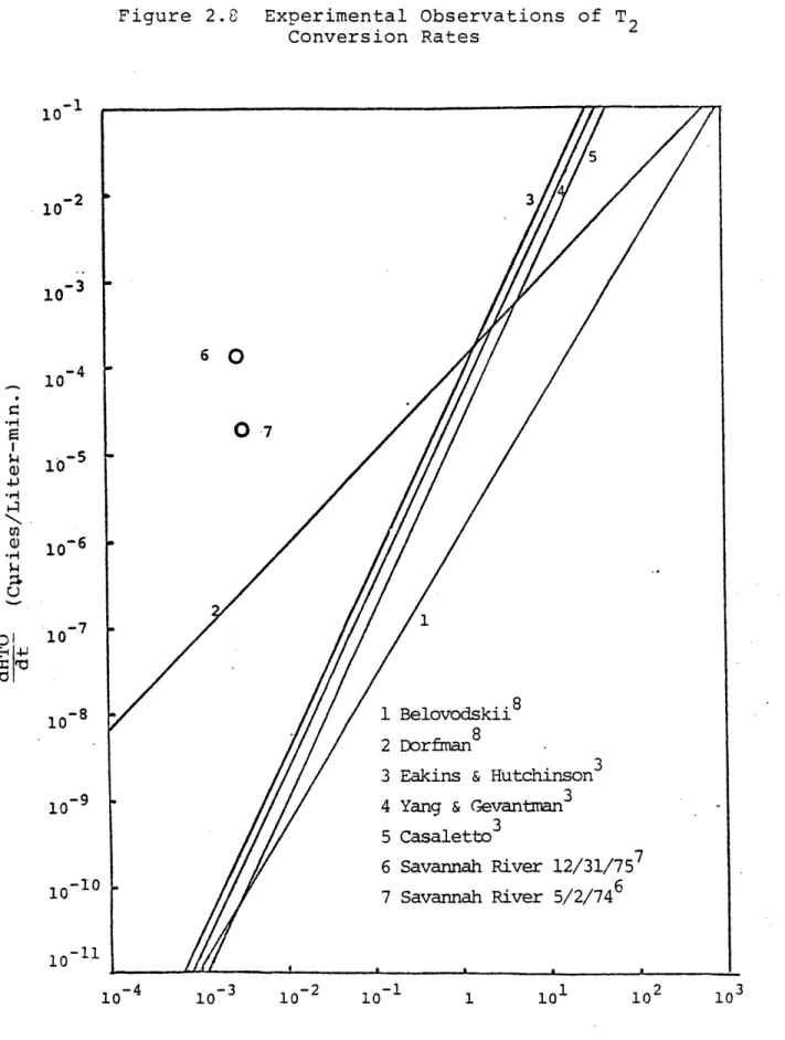
2.8 Experimental Observations of T2 Conversion Rates 52
2.9 Hydrogen Product Chemical Form as a Function of 62
(H2)/(AIR) Molar Ratio for (Li)/(AIR)
=
0.2123.1 Equilibrium Temperature vs. Lithium to Air Mole 80
No. Page
3.2 Equilibrium Temperature vs. Lithium to Nitrogen 81
Mole Ratio for Various Li Release Temperatures
3.3 Basic Containment Model 95
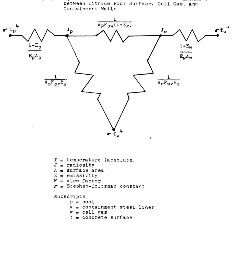
3.4 Equivalent Circuit for Radiation Heat Exchange 100
Between Lithium Pool Surface, Cell Gas, and Containment Walls
3.5 Cross Section of UWMAK-III Primary Containment 105
Building
3.6 Temperature History for a Lithium Fire in- the 115
UWMAK-III Containment (Run No. 1)
3.7 Temperature History for a Lithium Fire in the 117
UWMAK-III Containment (Run No. 12 & 14)
3.8 Temperature History for a Lithium Fire in the 119
UWMAK-III Containment (Run No. 21 & 23)
3.9 Temperature History for a Lithium Fire in the 120
UWMAK-III Containment (Run No. 6)
3.10 Temperature History for a Lithium Fire in the 122
UWMAK-III Containment (Run No. 15 & 18)
3.11 Temperature History for a Lithium Fire in the 123
UWMAK-III Containment (Run No. 24 & 25)
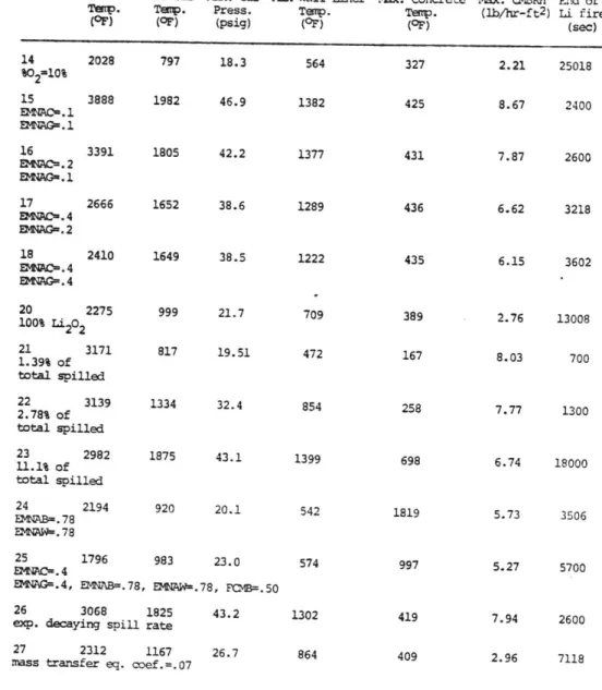
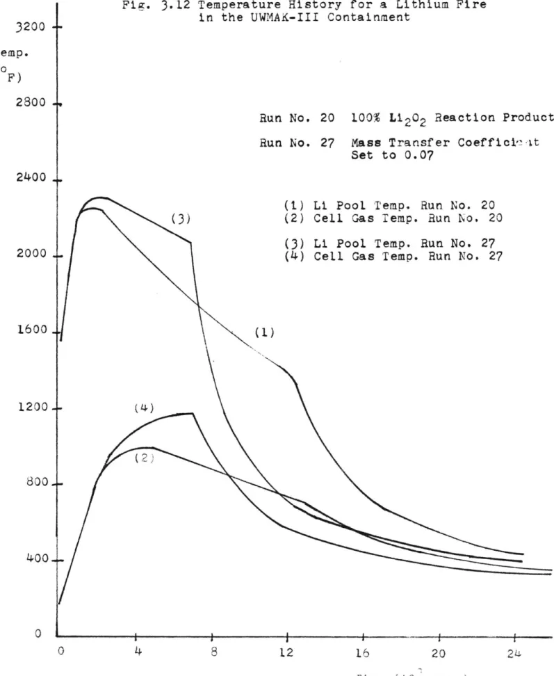
3.12 Temperature History for a Lithium Fire in the 124 UWMAK-III Containment (Run No. 20 & 27)
3.13 Change of the Maximum Lithium Pool Temperature 127
LIST OF TABLES
No. Page
1.1 Radiological Hazard Potential for Radioisotopes 7
of UWMAK-III (TZM Structure)
2.1 Activity and Biological Hazard Potential Values 20
for the Dominant Radioisotopes at Shutdown after Two Years Operation
2.2 Release Conditions for Reference Case and 27
Sensitivity Study
2.3 Sensitivity of Consequence Magnitudes to Various 29
Release Conditions
2.4 Exemplary Reliability Requirements from Comparisons 34
of Fission Risk Curves and Fusion Risk Profiles
2.5 Possible Tritium Release Inventories 47
2.6 Summary of Tritium Conversion Work 50
2.7 Savannah River Release Incidents 53
2.8 Percent of Hydrogen Released Which Forms the 57
Designated Product Versus (H 2) /(AIR) for
(Li)/(AIR) = 0.0021
2.9 Percent of Hydrogen Released Which Forms the 58
Designated Product Versus (H2) /(AIR) for
(Li)/(AIR) = 0.0212
2.10 Percent of Hydrogen Released Which Forms the 59
Designated Product Versus (H2 )/(AIR) for
(Li)/(AIR) = 0.212
2.11 Percent of Hydrogen Released Which Forms the 60
Designated Product Versus (H 2)/(AIR) for
(Li)/(AIR) = 1.06
2.12 Percent of Hydrogen Released Which Forms the 61
Designated Product Versus (H2) /(AIR) for (Li)/(AIR) = 2.12
Energy and Heat Sources and Sinks in UWMAK-I and III
No. Page
3.2 Heats of Formation and Changes in Gibbs Free 72
Energy for Li3N(c) and Li2O(c)
3.3 Thermodynamic Results from Sample Calculations 77
for Determining Adiabatic Flame Temperature
3.4 Melting and Boiling Points of Some Metals Being 83
Considered as First Wall or Structural Materials
3.5 Summary of Desired Features for Lithium Combustion 86
Model and Applicable Sodium Fire Computer Codes
3.6 Thermophysical Data Used in SPOOL-FIRE Heat 97
Transport Calculations
3.7 Input Values for the Base Case 107
1.1
Introduction
The effort to define the potential for electric power
production from nuclear fusion has significantly intensified
within the last few years. The choice among the energy
resource options is influenced by, among other factors,
the environmental impact of the technology associated with
each option. Thus, an early determination of the potential
advantages and hazards of each of the long-term energy options,
such as nuclear fusion, is an integral part of the effort to
define the desirability of each option in a risk-benefit
context.
Beyond this obvious goal of comparison among alternative
future energy sources, early attention to the environmental
and safety considerations will tend to minimize the
environ-mental hazards by appropriately influencing the fusion reactor
designs as well as research and development plans.
Thus, it
is not surprising to find several recent publications on
environmental and safety considerations in fusion power plant
designs.
1-
5Associated with any power system containing radioactivity
there exists a potential hazard or risk resulting from
possible accidental releases. A study of the risks associated
with commercial fission power reactors in the United States
6
From a radiological risk perspective, fusion reactor plants
appear to have inherently two potential advantages over the
fission reactors:
1) The radioactivity associated with the fuel cycle
itself is less hazardous than that of the fission
reactor fuel cycle. The radioactivity induced in
the structures depends greatly on the materials
employed. Hence, there is a large degree of
lati-tude in minimizing the total radioactivity in the
fusion reactors of the future.
2) The radioactivity of the structures so far
consid-ered in fusion reactor design is of a half-life
that is considerably shorter than that of the fission
reactors, which mitigates the problems of waste
disposal.
The broad objectives of the present study, which was
initiated in October of 1976, are:
1) To develop a methodology for assessment of
radio-logical hazards from fusion reactor power plants.
2) To develop design criteria to ensure adequately
low levels of radiological hazards of fusion power
plants.
It is obvious that such broad objectives have to be pursued
within the bounds of available reactor plant design data.
While several conceptual designs for fusion power plants
concepts. Thus, the UWMAK-III design has been selected as
a reference reactor plant for this initial study. The
UWMAK-III design has been described in sufficient detail to
allow a reasonable level of quantitative assessment of the
radioactivity inventory and distribution, and, hence,
radio-activity hazard analysis. However, in many respects, there
is sufficient similarity in safety and environmental concern
among the various fusion reactor designs to render the
conclu-sions from the present study relevant to other concepts. It
should be noted that the radioactivity inventories used in the
present study were among the highest possible in Tokamak
reactors since no credit was taken for isotopic tailoring to
minimize radioactivity. 8
Radiological hazards may be classified as associated with
routine releases from the reactor plant or with accidental
releases. The former case results in a "definite"
environ-mental impact while the later results in a "potential" impact.
The probability of the accidental impact is commonly defined
in "safety analyses" of a reactor plant. Assessment of the
realistic radiological hazards of both routine and accidental
releases involves combining the probability and the consequence
of the releases. In Figure 1.1, the steps undertaken in such
an assessment are defined. Such an assessment was employed
in the "Reactor Safety Study"6 pertaining to accidental
Task Safety Environmental Impact
Assess Radioactivity Inventory
1. Tritium
2. Structural
3. Corrosion products
Define Conditions of Radio- Perform Mechanistic Evaluation Define Rate of Release Under activity Release to Contain- of Faulty Conditions e.g.: Normal Operating Conditions
ment 1. Loss of Blanket Coolant 1. Tritium Diffusion
2. Loss of Diverter Coolant 2. Radioactivity Streaming 3. Loss of Magnet Coolant 3. First Wall Replacement 4. Containment events 4. Blanket Replacement
a. lithium spill
b. helium pipe rupture
Probability = 1.0 Establish Probability of Release of x ci/hr in Each Event Define Radioactivity Dispersion in Atmosphere Define Consequences of Release of x mrem/hr I~
Two major sources of radioactivity hazards are easily
identified: (1) the tritium inventory and (2) the activation
products in the structures. Tritium release to the atmosphere
is the major radioactivity source during normal operation.
However, under severe accident conditions where the structural
activation products may be released to the atmosphere, the
contribution of tritium to the total biological hazard
poten-tial may not be dominant.
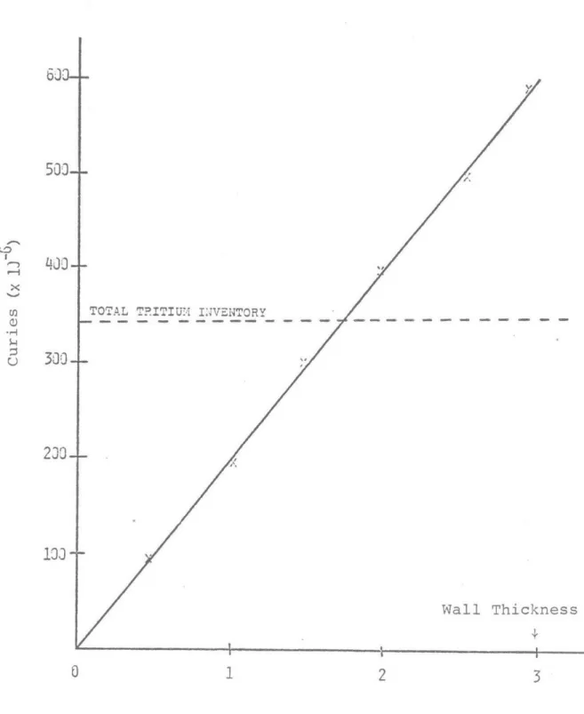
For UWMAK-III design, the potential radioactivity release
associated with vaporization of the TZM first wall is
illustra-ted in Figure 1.2. It is clear that the total radioactivity
of the first wall, which is roughly 25% of the induce4
radio-activity in the structures, is twice as large as radioradio-activity
of the tritium inventory. More significantly, tritium, a
beta particle emitter, can be permitted at a higher
concentra-tion in air than the structural nuclides. As shown in Table
1.1, the inventories of several isotopes will require larger
volumes of air to become diluted to the maximum permissible
concentration (MPC) than does tritium. Compared with the
energy requirement to vaporize the structural material, only
two sources of energy within the reactor plant appear to be
signigicant, as illustrated in Figure 1.3:
a) Lithium-Air or Lithium-Concrete reactions
b) The energy stored in the toroidal magnetic field.
Thus, considerable attention should be given to the mechanisms by which the available energy can be deposited in the first
wall, which has the highest specific (per unit volume) structural radioactivity.
Figure 1.2 First Wall Activity Inventory
63-
500--xV
TOTAL T.ITIU. INVENTORY
10-Wall Thickness
0
12
3
TABLE 1.1
Radiological Hazard Potential for Radioisotopes
of UWMAK-III (TZM First Wall)
PRINCIPAL FIRST WALL ISOTOPE TOTAL KM of TO DILUTE TO MPC 8.7 x 10⁷ 7.0 x 10 7 6.2 x
10 7
4.0 x 10 3.9 x 10 7 2. 2 x 10 7 1.72 x 10⁶ 1.5 x 10⁶ 1.5 x 10⁶ 3.3 x 10⁶ 2.1 x 10⁶ 5.7 x 10 5 5.7 x 10 5 2.4 x 10⁶ 5.7 x 10 5 8.7 x 10⁶ 7.9 x 10⁶ 6.2 x 10⁶ 2.8 x 10⁸ 3.9 x 10⁶ 2. 2 x 10⁶ 3.43 x 10⁸ 1.5 x 10⁵ 1.5 x 10⁵ 9.9 x 10⁶ 2.1 x 10⁵ 5.7 x 10⁴ 27.7 x 10⁷ 2.4 x 10⁵ 5.7 x 10⁴ TOTAL = 596.7 x 10 6Ci(For Total First Wall Inventory)
AIR TOTAL CURIES Nb 92m Zr 89 Nb 95m Mo 99 Nb 96 Nb 9 1m T Tc 101 Mo 101 Nb 95 Zr 95 Mo 93 Tc 99m' Mo 91 Y 88
Energy Requirement for Vaporization of First Wall
600
0~ 0 500 N 0 > 400 (D-W Energy Stored in Toroidal Field
0
)
300
0a) 200
1% UWM1AK-III Lithium Invent
0
100
Kinetic Energy of Plasma (
2
orv in 02
3 x 10⁹
J)
3
Depth of Vaporization (MM)In Chapter II, several considerations in assessment
of the hazards from the induced radioactivity and tritium
are presented. A proposed methodology to assess the
ad-missible occurrence rate of major releases is outlined.
The
pathways for tritium releases are defined.
In Chapter III, preliminary assessment of the important
factors in evaluation of reactor containment building response
to Li-air fire is presented. Also, the potential for
gener-ating sufficiently high temperatures during the fire to
vaporize the structural material is evaluated from basic
thermodynamic considerations.
Many aspects of the work reported here are under ongoing
investigation, and it is hoped that some of the uncertainties
may be reduced in the near future.
1.2
Summary
The following is a summary of the major results and
conclusions of this preliminary study.
1)
A methodology has been proposed to determine
admissible radioactivity release probabilities,
from comparisons of consequences of radioactivity
releases to established acceptable levels or risk.
One example of this technique is the use of the
results of the Reactor Safety Study, representing
an admissible risk for current commercial nuclear
power plants.
The release probability constraints
thus determined may be used to set major component
reliability requirements for a Tokamak reactor
design.
2)
To illustrate the proposed methodology,
pliminary calculations have been performed for
re-leases of stainless steel activation products.
The
admissible release probability is dependent on the
accident release magnitudes.
Therefore, a range of
possible values for this parameter must be determined
for each structural material. The consequences of
activation product releases are also sensitive to
the site population characteristics.
3)
For a release to occur, both disruption of
structural material and its transport from the
reactor are required. A study of the melting rates
of stainless steel and TZM for sudden energy dumps
shows that the steel, with a lower BHP value, melts
slower for a heat flux if no significant material
ablation takes place. If material ablation is
signi-ficant, the steel is then found to have a higher
melting rate than the molybdenum alloy.
4) Potential pathways for different release modes
of tritium have been defined.
5) Elemental tritium conversion rates to the oxide
form is such that the order of the reaction, the rate
of the reaction, and the dominant conversion mechanism
are not clearly established. An attempt to analyze
actual tritium releases with the presently accepted
conversion rates have been unsuccessful.
6) During lithium fires, a substantial amount of
the tritium released may be converted to condensible
lithium compounds. The principal products appear
to be LiH, LiOH, H20, and H2. The amount of these
products formed is highly specific to the lithium-air tritium-air molar ratios.
7) Thermodynamic considerations indicate that in
case of a Li-0 2-N2 fire, the maximum flame temperature
will be 2500*K or less, depending on the molar ratios
of the interacting materials. For oxygen-depleted
atmosphere, the maximum temperature will be 13154K
or less. The Li-02 reaction is dominant when the volumetric percentage of 02 in the 02-N 2 mixture is greater than about 1%.
8) The energy released in lithium-oxygen fires
may lead to a significant overpressure in
contain-ments of proposed plant designs. However, the degree
of overpressurization will depend on various
para-meters, notably on the oxygen concentration, heat
transfer rates from the interaction zone to the gases
and containment wall and floor. Several design
options to mitigate the consequences of a lithium
spill are being analyzed and will be reported on in
Chapter I References
1. D. Steiner and A. P. Frass, "Preliminary Observation
on the Radiological Implications of Fusion Power,"
Nuclear Safety, 13 (5), September-October, 1972.
2. F. N. Flakus, "Fusion Power and the Environment," International Atomic Energy Agency, Vienna, Austria, October 1974.
3. D. Okrent, et. al., "On the Safety of Tokamak-Type
Central Station Fusion Power Reactors," Nucl. Eng. Design 39, 215, 1976.
4. R. G. Clark, "Safety Review of Conceptual Fusion Power
Plants," BNWL-2024, November 1976.
5. J. Powel, Editor, "Aspects of Safety and Reliability for
Fusion Magnet Systems," BNL-50542, January 1976.
6. Reactor Safety Study, WASH-1400, United States Nuclear
Regulatory Commission, October 1975.
7. The University of Wisconsin Fusion Feasibility Study
Group, "UWMAK-III, A Non-circular Tokamak Power Reactor Design," UWFDM-150, July, 1976.
8. R. W. Conn, K. Okula and W. Johnson; "Minimizing Long-Term
Radioactivity in Fusion Reactors by Isotopic Tailoring,"
II. RADIOACTIVITY HAZARDS AND ADMISSIBLE RISKS
2.1
Introduction
Most of the radioactivity in Tokamak reactors with a
deuterium-tritium fuel cycle is in two forms:
the activated
structural materials exposed to radiation from the plasma
and the tritium used as a fuel for the fusion reaction and
bred in the reactor blanket. Serious accidents resulting
in the disruption of the reactor first wall or blanket
structural materials are required to release any induced
radioactivity. However, because of its mobility, tritium
poses a potential hazard due to normal operational releases
as well as releases resulting from accidents. The total
amount of activity'in a fusion reactor system may be.on the
order of
109
Ci.,
2which is comparable to the total inventory
at a commercial light water fission reactor plant.
The risk assessment report for commercial nuclear power
plants (WASH-1400)
1was based on analyses of the probability
of accidents that may lead to radioactive releases to the
atmosphere.
These releases were then used in a consequence
model, the Calculations of Reactor Accident Consequences
(CRAC) computer code,
to evaluate the probability of
exceed-ing consequences of a given magnitude as a result of
radio-active releases. A similar technique can be utilized to
investigate the potential hazard of the radioactivity in
Tokamak fusion reactor plants.
The sources of radioactivity
must be identified and the activity releasing accidents must
be described.
Some type of consequence model can then be
employed to translate the release accidents into risk curves
or consequence magnitude ranges.
The concept of an acceptable or admissible risk for
electricity generation utilitzing nuclear power may be
contro-versial, but can be useful in determining system reliability
requirements.
If the fusion reactor accident consequences
are compared to a risk curve representing an admissible risk
to the public (the risk may be defined in terms of probability
of adverse health effects) an admissible failure rate or
frequency of occurrence for release accidents can be derived.
Thus, if an admissible or tolerable level of risk is assumed
or established for nuclear power plants, then the allowable
rate of release or probability for certain accidents can be
determined and may be used to set reliability requirements
for major system components of a fusion power plant.
The goal of this work is to establish a methodology
to determine probable consequences of radioactivity releases
from fusion reactors under accident as well as routine
operational conditions and to utilize the consequence spectrum
to assess the reliability constraints for major Tokamak
2.2 Induced Radioactivity
During the operation of a fusion reactor, there will
inevitably develop an inventory of induced radioactivity, or
activation products, in the first wall and blanket structures.
The amount and assortment of radioisotopes will depend on
the nature of the particle fluxes, the type of structural
materials and, to some extent, the duration of exposure to
these particles. The designers of fusion reactor systems
should attempt to minimize the potential hazards presented
by this induced activity by developing reliable designs with
safety features and by proper selection of structural
mater-ials. Using the conceptual designs which are available
for Tokamak type reactors, the radioactivity inventories
can be identified and possible accidents can be examined to
determine the amounts of radioactivity that may be released
to the atmosphere. The characteristics of the releases must
'e described before a consequence model can be used to
calcu-late the risks to the public associated with these
reactors. Much work still needs to be done in this area of
accident analysis before useful and realistic consequence
results can be developed, however, some preliminary results
and an example of the use of the methodology are presented
in this report.
By examining the potential hazards of activation product
releases and comparing them with an acceptable level of
presented by commercial fission power plants, a system
reliability requirement can be established in the form
of a maximum tolerable activation product release rate.
This requirement would attempt to prevent induced
radio-activity in fusion plants from posing a greater risk
to the public than conventional nuclear systems. Also,
a comparison of the reliability requirements determined
for activation product and tritium releases should
re-flect the relative hazards that the two forms of
radio-activity represent in the risk assessment of fusion
reactor systems.
2.2.1
Radioisotope Inventory
The first concern in assessing the potential
radio-activity hazard is to determine the inventory and
distri-bution of activity in the reactor system. Two reasonably
well defined systems, UWMAK-I and UWMAK-III,4 will be
used to exemplify the Tokamak-type fusion power reactor
system. Studies have been made to determine the
activa-tion products which will be induced during the operaactiva-tion
of these reactors. The two systems employ different
blanket structural materials (316SS in UWMAK-I; TZM in
UWMAK-III).
Neither material was assumed to be tailored
to minimize radioactivity. If such tailoring were to be
used,16 the total radioactivity would be substantially
below that reported in References 3 and 4.
' A calculational scheme has been developed at the
University of Wisconsin to determine the blanket
activa-tion product inventories.5 The model computes the
activity per kilowatt for each radioisotope, which can then
be divided by their maximum permissible concentration in
air (MPC) to obtain a quantity known as the biological
hazard potential (BHP). The MPC values are determined by
the best available data on the biological effects of each
radioisotope. When this biological data is lacking, a
conservative, or low MPC value is used, resulting in a
high BHP value for the particular isotope.
Using the BHP values from Reference (5), a list of
significant isotopes was compiled for each structural
material, excluding all isotopes with half lives less than
25.0 minutes and all those contributing less than
approxi-mately 1% of the total BHP of the remaining group. The
half life criterion was used in the Reactor Safety Study
(WASH-1400)1 to simplify the consequence calculations by
greatly reducing the number of radioisotopes that had to be
considered. This is based on the assumption that these
isotopes would contribute little hazard in an accident
situation due to the delay between shutdown and the time
it would take for radioactivity to reach the nearby
popu-lation. The change in the total radioactivity between
shutdown and 30 minutes is relatively small for the
isotopes are listed in Table 2.1. The activities, BHP
values and the isotopes themselves are all subject to
change as more information on biological effects of
var-ious radioisotopes is developed and the computational
model is refined.
The activation products are concentrated in the
blanket regions of the Tokamak reactor with a large
fraction of the hazard potential in the first wall.
Detailed descriptions of isotope distributions in the
blanket regions are not available at present, however,
they will only be necessary or useful when detailed
accidental release mechanisms and sequences are defined.
2.2.2. Radioisotope Releases
Most of the attention given to induced radioactivity
in fusion reactors has focused on the problems of waste
disposal and reactor maintenance, and relatively little
has been done to investigate its release into the atmosphere.
The release of activation products requires the disruption
of the first wall or blanket, escape of radioactivity from
the reactor into the primary containment, and finally, a
breach of containment structures. The first wall and blanket
structures are part of a vacuum vessel which is surrounded
by large magnet coils, piping and structural members. This
assembly is encased in shielding and is completely enclosed
by a primary containment.
-TABLE 2.1
Activity and Biological Hazard Potential Values for the
Dominant Radioisotopes at Shutdown after Two Years Operation
Radioisotopes
Structural Materials
316SS
TZM
activity
BHP
activity
BHP
3
3
(Ci/kWth)
(km air/kWth)
(Ci/kWth)i (km air/kWth)
Mn-54
75.6
75.6
Mn-56
388.
19.4
Fe-55
258.
8.6
Co-57
26.0
26.0
Co-58
131.
65.5
Co-60
6.21
20.7
Ni-57
4.5
4.5
Zr-89
8.97
89.7
Zr-95 2.2 2.2Nb-95
6.9
2.3
Nb-96
4.59
45.9
Mo-99
28.7
4.1
1204.
172.
Tc-99m
1450.
2.9
With an inert atmosphere and steel liners on exposed
concrete surfaces, to prevent or mitigate the exothermic
liquid metal reactions with air and concrete, the possible
energy releases for a fusion reactor system appear to be
smaller than for a fission system.
The possible energy sources for the disruption of the
structures are the magnet system (including the liquid helium coolant), the plasma, the liquid metal coolants, and the after heat or decay heat in the first wall and
blanket after shutdown. The plasma, with a total energy on
the order of 109 J, could melt or vaporize part of the
first wall if a quench was sufficiently localized.4 However, this event itself is not likely to result in a breach of
the reactor structures. The much larger stored energies associated with the toroidal magnetic field, which is on
the order of 101 J,4 could result in disruption of part
of the structures (see Figure 1.3) if there is a mech-anism by which a sufficiently localized energy dump
can occur. The helium coolant of the magnet system could
potentially cause structural damage due to thermal
inter-actions and overpressurization following its vaporization.
Large amounts of heat energy could be generated by liquid
metal interactions with air and concrete resulting in
potential structural damage and volatilization of activation
products. However, as discussed in Chapter III, lithium-air
would melt blanket materials like stainless steel, but not
TZM. Also, it has been suggested that highly reactive
chemical species such as oxygen, hydrogen and nitrogen
could be released during liquid metal fires and may lead
to the rapid ablation of the first wall materials.
2Much of the future work concerning the induced
radio-activity will be directed towards determining how energy
may be deposited in activated structures, the extent of
possible material disruption and the amount and form of
radioactivity which may be released from the reactor
and the containment structure. This information is crucial
for any attempt at assessing the possible hazards of
induced radioactivity in a Tokamak fusion reactor.
2.2.3. Consequence Calculations and System Reliability
Requirements
Preliminary studies have been performed to construct
event trees for accident sequences,2 but due to the conceptual
nature of the reference designs, determination of release
maximum permissible risk criterion, calculations of various
release consequences can establish a maximum tolerable failure
rate, which may in turn be used to set reliability
require-ments for major reactor system components.
This approach
avoids the necessity for detailed design definitions, which
are not presently available and are not likely to be developed
in the near future.
The calculations of release consequences requires the
determination of the radioisotopes involved, the fraction
of the inventory released to the atmosphere, the conditions
which describe the radioactive plume, and specification of
the weather conditions and population distrubution around
the reactor site.
In the present study, the computer code
developed for the Reactor Safety Study (WASH-1400), the CRAC
code, is being modified to handle releases of the activation
products.
The output of the consequence code, which is in
the form of consequence probability distribution functions,
can be used to determine the required limitations on failure
rates. A description of the CRAC code and the methodology
for determining the reliability requirements, along with a
preliminary example of this technique, will be presented
in the rest of this section of the report.
2.2.3.a Consequence Model
1The "Calculations of Reactor Accident Consequences"
(CRAC) code was developed, as part of the Reactor Safety
Study, to perform the computations to determine consequence
magnitudes and their probabilities for potential releases of
radioactive materials following commercial nuclear fission
power plant accidents. A schematic outline of the model is
shown in Figure 2.1. The starting point for the calculation is
the magnitude of radioactivity released to the atmosphere. For
the commercial nuclear plants, the spectrum of releases were
discretized into nine Pressurized Water Reactor and five Boiling
Water Reactor categories, each with an associated probability of
occurrence and release magnitude.
(As applied in the present
study, a certain fraction of the radioactivity inventory was
assumed to be released, without assigning any probability for
the release.)
A meteorological model computes the dispersion
and deposition of radioactive materials as a function of time
after the accident and distance from the reactor. This model
incorporates factors accounting for the decay of the
radio-activity and includes the effects of thermal stability, wind
speed and precipitation in a Gaussian dispersion model. The
temporal variations of these weather parameters are obtained
by using samples from a year's weather data from reactor sites.
Variations of the mixing layer are included. The effects of
the plume lifting off the ground due to the release of sensible
heat is also included, and the plume is not allowed to
pene-trate the mixing layer.
Once the concentration of the radioactivity in the air and
on the ground is determined, the model calculates the possible
doses from various modes of exposure. These include external
Figure 2.1
Schematic Outline of Consequence model
and internal irradiation from inhaled radioisotopes and
ingestion of contaminated crops, water and milk. The
distribution of people about the reactor site is used along
with an evacuation model to obtain a set of doses for the
affected population. These doses are transformed to actual
health effects, such as early (within a year) fatalities,
early illnesses, cancer deaths and genetic effects. The
health effects are used as the measure of the accident
consequences.
The final results, which include property damage in
addition to health effects, are formed by combining the
conse-quence probability distribution functions for the spectrum
of release conditions at the various reactor sites using the
spectrum of weather conditions. Thus, the assessment of a
large number of individual reactor accidents is then expressed
as a set of complementary cumulative distribution functions
for each of the potential consequences.
2.2.3.b Example to Illustrate Methodology
A preliminary determination of the consequences of
stainless steel activation product releases has been performed.
Since specific values for the required parameters, which
describe the possible releases, have yet to be defined for
accidents in a Tokamak system, values were chosen which were
similar to those used for fission reactor accidents in
WASH-1400. The values were varied to determine the sensitivity of the consequences to each parameter. Table 2.2 summarizes the cases that were investigated, where the reference case
TABLE 2.2
Release Conditions for Reference Case and Sensitivity Study
Parameter Reference Case Range of Variation:
Sensitivity Study
release magnitude
(percent of total
inventory)
time between shutdown
and release (hrs.)
warning time to
evacuate (hrs.)
energy release rate
(cal./sec.)
release height (m.)duration of release
(hrs.)
1.00.5
0.5 0.1 - 3.0 0.25 - 1.0 0.25 - 1.0 104 - 107 1 - 2525
0.5 - 10.0}
3.0denotes the one used in the preliminary example calculations
of system reliability requirements.
It was found that the consequence magnitudes were
strongly dependent on certain conditions and parameter values.
The reactor site population distribution and the release
magnitude were the most influential parameters.
The time
delay between shutdown and release, the warning time to
evacuate, the energy release, the duration of release, and
the release height all had secondary effects on the
conse-quence magnitudes. Table 2.3 summarizes the influence of
these parameters.
To determine the actual reliability requirements, or
admissible failure rates, the fusion reactor accident
conse-quences must be compared to similar risk assessments for
systems posing acceptable public hazard levels. Using the
results of the Reactor Safety Study1 to establish an
accept-able hazard level for nuclear power generation, a probability
distribution function for a particular fission reactor
accident consequence can be compared with a normalized
prob-ability distribution function, or "risk profile," for the
fusion reactor accident, to graphically produce a maximum
admissible failure rate. This maximum tolerable frequency
of occurrence prevents the public risks associated with a
particular fusion reactor accident, or set of accidents,
from exceeding the risks calculated for fission reactors.
The same technique could be used to compare risk profiles
TABLE 2.3
Sensitivity of Consequence Magnitudes to Various Release Conditions
Parameter Increased Change in Consequence Magnitudes
population density increase
release magnitude increase
time between shutdown decrease
and release
warning time to evacuate decrease
energy of release increase
release height increase for illnesses;
decrease for fatalities
duration of release consequence increase for
release durations of up to several hours (exact time
depends on release magnitude), then decrease f'or longer
durations
*
for fusion reactor accident consequences with other similar
risk assessments that have been deemed to represent an
acceptable level of risk.
As an example, Figure 2.2 contains the early fatality
probability distribution curve for a fission plant on a
highly populated site with particularly unfavorable weather
conditions. Plotted on the same graph is the probability
distribution profile for the same health effect consequence
resulting from the release of about 1% of the Tokamak reactor
inventory of stainless steel activation products. The fusion
reactor is on the same site and the release occurs with the
same weather conditions used for the fission reactor, and
the release conditions are those of the reference case. The
fusion curve is normalized in the consequence model because
a frequency of occurrence equal to one per reactor-year is
assigned to the release. The comparison process consists of
placing the normalized curve on the probability-consequence
graph as far up on the probability scale as is possible while
remaining totally beneath the fission curve. The ordinate
intercept, which in this case is 10~4 per reactor-year,
determines the maximum allowable probability for the releases.
It must be emphasized that these curves have been developed
and used to demonstrate a methodology and should not be
considered as having any significance in a risk assessment.
The same fusion reactor consequence probability profile
may be compared to the early fatality complementary
Figure
2.2
An Example
of the method to Determine maximum Admissible Failure Rates Using Fission Risk Functions and Fusion Risk ProfilesEarly Fatalities: Using the Highly Populated Site Fission Curve
0 .4J U
a
~0
CL 10410
10
10
5
-6
-7
1
10
100
1000
10,000Number of Early Fatalities
Note: Both computations
of severe weather
employ the equivalent
conditions, therefore,
of an entire year the results do not represent actual risk assessments.
IT
- FISSION
-T
17'' 10
.
reactors at the various sites and with the spectrum of weather
conditions employed in the Reactor Safety Study. An allowable
failure rate of 10~
per reactor-year is then obtained
revealing the inherent conservatism in using only the highly
populated site for the fusion reactor. Further studies will
include the development of composite curves for fusion reactors
with various sites and weather conditions, providing a more
valid comparison with the composite fission curves. Similar
results are obtained from Figure 2.3 in which early
illness probability distribution curves are compared. The
preliminary reliability results are summarized in Table 2.4.
A particularly interesting relation between the admissible
release rate and the release magnitude is shown in Figure 2.4.
The two curves are derived from a series of normalized early
fatality and early illness probability distribution profiles
for various magnitudes of activated steel releases from a
Tokamak reactor on a highly populated site, which were compared
with the two corresponding probability distribution functions
for fission reactor accidents on the same site with the same
weather. The curves in Figure 2.4 reveal that the reliability
requirements for the fusion system are very sensitive to the
possible release magnitudes, and that releases of more than
approximately 2% of the steel activation product inventory
should be limited to the very low rates of less than 10-6 per
reactor-year.
Fiqure 2.3
An Example of the method
to Determine maximum Admissible Failure
Rates Using Fission Risk Functions
Early Illnesses:
10-2
10
-31-4
Using the H-ighly
and Fusion
Populated Site
Risk Profiles
Fission Curve100,000
1,000,000
Number of Early
Illnesses
Note: Both computations employ the of severe weather conditions,
equivalent therefore,
of an entire year
the results do not represent actual
(u 0 .0-U (U 914 1 P-4 -0 0 - N-tFISSION F
10
100
1000
10,000
risk assessments.TABLE 2.4
Exemplary Reliability Requirements from Comparisons of Fission Risk Curves and Fusion Risk Profiles
Fusion Profiles Fission Curves Admissible Failure
Rate
(1% inventory release) (from WASH-1400) (per reactor-year)
early fatalities:
early fatalities high pop. site 1 x 10~4
early illnesses:
10-Fiqure 2.4
Sensitivity of the Exemplary Reliability Requirements to the Stainless Steel Activation Product Release Magnitudes
10-4
0.5 1.0
1.5
2.0
2.5
Release magnitude
(percentage of total inventory)
Note: The numerical values are not
as significant
characteristics of
0-2
CU U V-3
10
1-J,
0. CU EV r-4 CU E EARLY ILLNESSES E ARLY FATALITIES3.0
as the 1-6
A similar methodology can be used to investigate other
possible structural materials. Initial considerations of a
TZM first wall have been undertaken.6 Analysis of the
response of first wall materials to an energy dump reveal
that the relative melting rates for TZM and stainless steel
depend on the rate of the energy dump. For an energy dump
during which material ablation does not occur, TZM meltsfaster than the steel. If material ablation is involved,
the steel will have the higher melting rate. Since the
molybdenum alloy has a larger BHP value associated with its
induced activity, it appears that TZM may pose a greater
hazard than the stainless steel when considering release
accidents. Further study will investigate the effects on the
consequences and reliability requirements of this material
choice.
Future efforts concerning the potential hazards of
induced radioactivity will center on the determination of
important parameters describing possible release accidents
in Tokamak systems. Knowing these parameters with greater
certainty, more realistic consequence calculations may be
performed and the subsequent reliability requirements may
serve as a valid basis for system designs. Most importantly,
however, a methodology with which a radiological hazard may
be translated into system reliability requirements will be
2.3 Tritium Radioactivity Releases
One of the most abundant radioisotopes which will be
present in fusion reactors operating with the deuterium
-tritium fuel cycle is -tritium, an isotope of hydrogen that
decays via beta emission with a half life of 12.36 years.
Tritium inventories in proposed fusion reactor designs
range from 5 to 36 kilograms (about 5 x 10⁷ to 36 x 107
curies). In the latter case, this amount represents about
three times the present (1977) natural, steady-state
inven-tory of the atmosphere. Boiling water reactors release from
1 to 100 Curies/reactor/year whereas pressurized water
reac-tors release about 600 Curies/reactor/year. In 1963 the
total tritium inventory in the atmosphere went as high as
7
2000 MCi because of atmospheric weapons testing.
A limiting factor in fusion reactor environmental impact
and safety research is the lack of detailed design data. The
UWMAK-III conceptual Tokamak fusion reactor has been examined
for tritium hazards since the design report for this reactor
has the most developed tritium handling system described for
fusion reactors.4 The analysis of the tritium hazards in the
UWMAK-III reactor design will in a large part be applicable
to other conceptual fusion reactor designs using a D-T fuel
cycle.
There are four types of coolant used in the UWMAK-III
design. The inner hot shield is cooled by helium gas which
is circulated in a closed cycle to a helium turbine which
Energetic tritons and alpha particles diffusing from the
plasma are diverted via magnetic fields and impinge on the
divertor section of the vacuum chamber. The heat deposited
in the divertors is transferred via a liquid sodium loop
through a steam generator to a conventional Rankine cycle
steam turbine system which produces 285 Mw(e).
The plasma operates on a deuterium-tritium cycle and for
this reason it is desirable to breed tritium in the reactor.
This is accomplished by the use of liquid lithium as a blanket
material in the outer portion of the torus. The 14.1 Mev
neu-trons produced by the fusion reaction interact with the lithium
via:
6
Li + n = He + 3H.
The liquid lithium then goes to an intermediate sodium heat
exchanger and this sodium then flows through a sodium-helium
heat exchanger. The hot helium is then used to drive two
turbines which are identical to the turbine used in the inner
blanket power cycle.
The fusion reaction in the Tokamak is pulsed with a
plasma burn time of thirty minutes. The duty factor of the
power cycle is 95%. During the down time of the cycle it is
necessary to provide a thermal storage medium so that the
production of electricity in not interrupted. The intermediate
sodium serves in this capacity. The total power system uses
dry cooling towers for waste heat rejection. The power cycle
V= 1170m 3 ) A=.23Xt04m2,_
UWMAK -
II
3.56X O6ka/hr ^= 5850m2 5900C *C CO1T!NUOt ; I i 7 OM
V\i~c)lHo
ud 2.86 X 0G kg /hr87[0 *Cl
e
I-:-
LO'o
P = 13 33". -1:,' (U CON Ti NUOUS 585 M ., ( c) FROM DIVERTOR S TEA MV =352m GENERATOR STEAM CONDITION
600*C 6000C ~, 538*C 2400psi P = GG0,7 k-.:'V/ (1) No at 1.0LOX0 1 kg/hr CONTINUGUS 40C294 4 M (e) V=352m3 V=1170 = 6150 m2 LA,)
2.3.1 The Tritium Fueling System
The tritium extraction system in UWMAK-III has been
de-signed to maintain a tritium partial pressure in the
contain-ment of 7.6 x 10⁻¹ Torr. This is achieved by back-designing
the coolant system and fuel extraction devices to insure loss
rates to the building environment of less than 1 Curie per
day. The tritium handling facilities of the UWMAK-III system
are outlined in Figure 2.6.The steady-state tritium concentration in the lithium is
about 2.08 ppm. The circulation rates and inlet and outlet
temperatures of the heat transfer fluids are shown in Figure
2.5. The lithium passes over a niobium-palladium-yttrium
"window" designed like a heat exchanger and the tritium
dif-fuses through the window. The tritium then emerges on the
downstream side where it catalytically reacts with oxygen in
a flowing helium stream. The T20 is then adsorbed on
molecular sieves and the helium and oxygen are recycled.
The sieves are regenerated by heating and the T2 is sent to
the tritium storage area. As is the case with most of the
fuel separation columns in the UWMAK-III system, this section
is operated in tandem modes--while one set of adsorbers is
collecting tritium, the other set is regenerating.
The production of tritium in the liquid lithium is
accom-panied by the production of an equal amount of helium.
Impuri-ties cleanup and helium venting would require diversion of
about 1% of the lithium flow whereas the tritium extraction system would require diversion of about 5% of the total lithium flow.
--ECOVERY -: FUE L I:,'G
I--- - -- Ho COOLA*r
US- LIQ. IiETAL COOLANT
It Y
400 SEDS 'T2
4Q00 STEAM
DIV No 600* GEN DUIP ,
B EDS '" ~~ ~~~lI, 30* 0 --<630* 5r0 LI Li 9800 HX No 94,0 liX TU[CINE 9
DUUP 1-e
670* NT2 0 TANK [7, T20 !,jLFLCj If'C n . . .j. I1 0Tritium diffuses into the sodium IHX and into the sodium
in the divertor power system. This tritium must be extracted.
In both cases, the cold leg sodium will react with a yttrium
getter bed system operating in tandem modes.
Tritium can form in the inner shield via neutron
inter-action with the boron in the boron carbide. This tritium can
diffuse into the inner blanket helium coolant. Since this
helium goes directly to the turbine hall it must be continually
processed for the removal of tritium.
The tritium extracted from the lithium blanket flow is
transferred to the T2 storage.facility. The T2 is stored in a
gaseous form, under pressure, in an austentitic stainless steel
tank. The tritium extracted from the yttrium beds and the
helium cleanup system must first be purified before use as a
fuel.
Solid fuel pellets are injected into the torus during the
burn cycle. 1.63 kg of T2 and 1.085 kg of D2 are injected
dur-ing the burn. Only 0.620 kg of T2 and 0.413 kg of D2 are
con-sumed. The unburned fuel is collected in cryopumps and adsorbed
on molecular sieves. One set of cryopumps is in operation while
the other set is being regenerated. The process stream is
puri-fied and the various hydrogen isotopes are separated and sent to
storage.
The total tritium inventory in UWMAK-III is reported to be
35.8 kg. A complete description of the tritium handling system
2.3.2
Containment Systems and Equipment Locations
The plant schematic for the reference design is shown in
Figure 2.7.
The four buildings that are of primary concern in
this analysis are the reactor containment building, the heat
exchanger building, the auxiliary building, and the turbine
hall. Only the latter does not have a specified emergency
detritiation system.
The emergency containment detritiation system is designed
to process the building atmosphere for tritium removal in the
event of a release.
The buildings are designed to operate with
inert atmospheres but this may be neither economical nor
practi-cal.
In any case, a normal atmosphere must be used for
mainte-nance operations.
Additional safety can be provided by the use of secondary
containment systems used to isolate components with high tritium
inventories.
Techniques similar to those developed at Mound
Laboratories can be used to control tritium releases from such
components.9
The tritium bearing systems of major concern in the reactor
containment area:
Helium piping
Sodium piping
Lithium piping
Vacuum chamber
Cryopumps
Pellet Injection system
The sodium and helium piping are exposed to the reactor room.
The lithium piping is double walled to decrease the tritium
permeation rates and permit the passage of a helium sweep gas
Figure 2.7
Plant Schematic - UWMAK-III
The torus is composed of 18 removable sections which are
replaced every 2 years. Since some leakage is expected through
the seals, the design calls for a chamber to surround the torus,
field coils, and cryopumps. This chamber will be held at 75
Torr to reduce pumping losses. This chamber may need a
detri-tiation system. The pellet preparation system and the pellet
injector are also prime candidates for glovebox detritiation
systems because of their unusually high tritium inventories.
The tritium bearing systems of major concern in the heat
exchanger building are:
Helium piping
Main lithium piping Diverted lithium piping Divertor yttrium beds IHX yttrium beds
Sodium impurities cleanup lines Regenerators and hea.t exchangers
Sufficient design data is not available to determine whether
secondary containments are feasible in the heat exchanger
build-ing. Whereas the yttrium beds are located near the main sodium
lines, the regenerated tritium must be pumped to the auxiliary
building for purification. About 1% of the sodium from the
Divertor and IHX can be channeled to the auxiliary building for
cleanup. Likewise, 5% of the lithium stream can be diverted
to the auxiliary building for tritium extraction and cleanup.
The only tritium not contained in the liquid metal coolants in
the heat exchanger building is in the yttrium bed process
lines. The coolant tritium inventories would be released only in the event of a sodium or lithium spill. Releases from these