HAL Id: hal-01742176
https://hal.archives-ouvertes.fr/hal-01742176
Submitted on 23 Mar 2018HAL is a multi-disciplinary open access
archive for the deposit and dissemination of sci-entific research documents, whether they are pub-lished or not. The documents may come from teaching and research institutions in France or abroad, or from public or private research centers.
L’archive ouverte pluridisciplinaire HAL, est destinée au dépôt et à la diffusion de documents scientifiques de niveau recherche, publiés ou non, émanant des établissements d’enseignement et de recherche français ou étrangers, des laboratoires publics ou privés.
A 50 µW Microbial Fuel Cell Isolated Energy Harvesting
Interface Based on Air Coupled Inductors
Yohan Wanderoild, Adrien Morel, Armande Capitaine, Gaël Pillonnet
To cite this version:
Yohan Wanderoild, Adrien Morel, Armande Capitaine, Gaël Pillonnet. A 50 µW Microbial Fuel Cell Isolated Energy Harvesting Interface Based on Air Coupled Inductors. Journal of Low Power Electronics, American Scientific Publishers, 2018, 14 (1), pp.170 - 178. �10.1166/jolpe.2018.1538�. �hal-01742176�
See discussions, stats, and author profiles for this publication at: https://www.researchgate.net/publication/323871879
A 50 μ W Microbial Fuel Cell Isolated Energy
Harvesting Interface Based on Air Coupled
Inductors
Article in Journal of Low Power Electronics · March 2018 DOI: 10.1166/jolpe.2018.1538 CITATIONS 0 READS 11 4 authors, including: Some of the authors of this publication are also working on these related projects: energy harvesting microbial fuel cell View project Capacitive adiabatic logic View project Yohan Wanderoild Atomic Energy and Alternative Energies Com… 8 PUBLICATIONS 5 CITATIONS SEE PROFILE Adrien Morel Cea Leti 12 PUBLICATIONS 4 CITATIONS SEE PROFILE Gael Pillonnet Cea Leti 79 PUBLICATIONS 255 CITATIONS SEE PROFILEAll content following this page was uploaded by Adrien Morel on 20 March 2018.
A 50µW Microbial Fuel Cell Isolated Energy Harvesting
Interface Based On Air Coupled Inductors
Y. Wanderoild1*, A. Morel1, A. Capitaine1, G. Pillonnet1
Abstract — Microbial fuel cells (MFCs) are emerging energy harvesters that are promising
for the autonomous supply of remote sensors on the seabed. The low voltage delivered by the MFC’s, a few 100mV, imposes an electrical interface to boost the latter to the sensor’s needs. The flyback in discontinuous conduction mode appears to be the best candidate since it allows the maximum power delivered by the MFC to be extracted, the sensor to be electrically isolated from the source and the voltage to be boosted that required by the energy buffering. Our previous work highlighted the significant impact of the magnetic core loss due to hysteresis and magnetic saturation even at µ-scale energy transfer. In this paper, we propose to remove the magnetic core to suppress these losses. The low density harvested power (100µ W for 10thcm² electrodes) and low-size constraint i.e. 1m² scale in seabed remote sensors applications allows us to use 0.5 m² air-core inductance by plugging in a 20-cm² MFC, delivering a maximum power of 90µ W at 0.3V. The proposed air-core coupled inductor based flyback achieved 60% efficiency experimentally from end to end peak. These results are 10% lower than those achieved with a magnetic core.. This decrease is due to the increase in the losses generated in the active components. However, the experimental results are in good agreement with simulations in which a model of the coreless coupled inductances, extracted from characterizations, is used. Finally, potential improvements linked to custom designed components due to progress in active components such as transistors and diodes are also discussed. A thorough analysis led us to think that in the future, the coreless solution may surpass its magnetic counterpart, and hence become a viable alternative.
Keywords — Energy harvesting; Coreless transformer; Coupled coils; Flyback converter; Impedance matching; Microbial fuel cell, Scavenging.
1
I
NTRODUCTIONDuring the last two decades, there has been a growing interest in making sensor nodes autonomous. Scavenging ambient energy seems to be a promising solution, offering a sustainable, eco-friendly alternative/complement to chemical batteries [1]. Thus, harvesting solar [2, 3], vibrational [4, 5], or thermal [6, 7] energies has been widely studied as they seem to be in most cases the greatest sources of energy. However, in some very particular places exhibiting unusual and harsh conditions, such as deep ocean floors, these energies are insufficient to power a sensor. Indeed, sunlight cannot reach these floors, and vibration and thermal gradients can be considered unusual.
In order to supply deep-sea floors sensors, new harvesting technologies, microbial fuel cells (MFC’s) which require no light, thermal gradient or vibration, have been investigated. In fact, MFC’s only require waste materials to produce energy. MFC’s power can be generated from the oxidation of organic matter by bacteria, hence enabling the conversion of chemical energy from a large range of carbonate substrates (such as oolitic aragonite, coral skeletons, or crushed
marble) into useful electrical energy [8, 9]. The main drawbacks of MFCs are their poor
generated power density (around 5µW/cm²) and the extremely low potential generated (below 0.7V) which is in most cases insufficient to be in the operating voltage range of a sensor node.
First, it was proposed to use a boost converter in discontinuous mode in order to both maximize the power extracted from the MFC while increasing the output voltage [10, 11]. The use of a flyback converter has also been investigated in the literature, as it creates a galvanic isolation between the MFC and the sensor [12]. This Flyback topology also has the advantage of allowing the use of multiple separated harvesters: a single secondary coil could be used with many primary coils, each connected to a single MFC. This also allows MFC’s to be in parallel/series in order to maximize the extracted power [13].
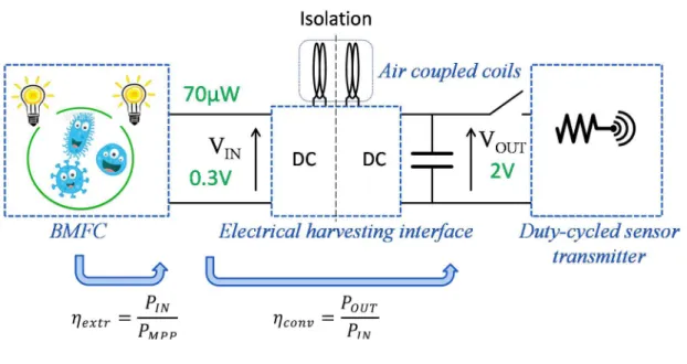
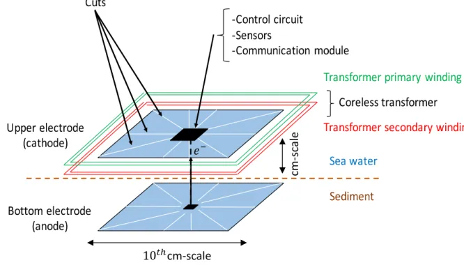
The main flyback losses observed in previous work [14] were due to magnetic losses in the magnetic core, which drastically limited the harvested power. However, in this paper, we propose a new Flyback converter based on a coreless coupled coil, which could potentially lead to less magnetic losses and thus a higher efficiency. This could also allow the switching frequency boundary, imposed by the saturation and hysteresis, not to be constrained. However, using a coreless transformer leads to new challenges that need to be tackled. For example, due to the absence of a core, the air transformer is several orders of magnitude less inductive than its magnetic counterpart (with an equal surface). Thus, in order to achieve a more inductive transformer, the coil sizes have to be increased by an order of magnitude. However, in the MFC energy harvesting context, since the reaction has low kinetics, relatively larger compounds are needed, reducing the size constraint generally imposed. The lower coupling end magnetic losses, and the higher coil radius all in all lead to new optimization constraints, which are investigated in this paper. The final structure is presented in Figure 1. It depicts the benthic MFC (BMFC) supplying the sensor and its transmitter thanks to the proposed coreless electrical harvesting interface.
In the first part, we discuss the MFC models, and also how to maximize the extracted power thanks to the Flyback converter. In the second part, we introduce the coreless transformer models as well as a loss analysis. Thanks to this modeling part, we have been able to numerically determine the optimal parameters for our coreless transformer. In the third part, we attempt to experimentally validate the theoretical models, using two coreless converters. Potential improvements as well as the future of coreless-based converters are discussed in the final part.
2
H
ARVESTING SYSTEM MODEL AND ANALYSIS2.1 The BMFC
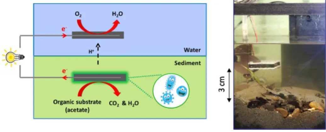
Figure 2. The BMFC, operation principle and prototype
Among the estimated existing 10 million bacterial species, some are electro-active. These can thus oxidize organic material and so create an electron flux that can be channeled to harvest the energy produced. In the case of the BMFC, as shown in Figure 2 the sediment acts as a membrane, the cathode reduces the oxygen into water and the anode located in the sediment is oxidizes the organic material acetate into bicarbonate. The theoretical potential of the cell formed is 1.1 Volts. However the measured open-circuit potential is generally 0.7V. This difference is due to fluctuation in the concentration around the electrodes and also parasitic reactions. The static behavior of the BMFC has been studied in [9]. Its
characterization requires much time since each working point needs to be characterized after one hour, when the cell reaches its steady state. It has been proven that there is a large voltage
range where the behavior of the BMFC can be assimilated with a voltage source = 0.6V)
in series with a resistance . If the cell is less than 1 m² the BMFC resistance R can be
estimated by R 2.6/S , where S is the electrodes surface in m². As a result, to simplify the
testing process and modeling, the equivalent model will be used to emulate the fuel cell behavior. Based on these considerations, we can conclude that the maximum power extracted from a MFC can accurately be given by (1). The associated working point is called the maximum power point (MPP) shown on Figure 3 and is reached when the output voltage of the cell is equal to half of the open circuit BMFC voltage.
∙ . / ²] (1)
Figure 3. BMFC characterization and harvestable power
To work at the MPP and adapt the voltage to the load, as shown on Figure 3, a converter is
needed. Two efficiencies are hence defined, as depicted on Figure 1. First, , the extraction
efficiency is maximized when the input voltage of the converter, !", is fixed at the optimal
the BMFC. %&'( is maximized when the converter losses are minimized. In most cases, we
would like to maximize the output power for a given input power, which consists in maximizing
the product × %&'(.
2.2 Flyback converter in discontinuous mode
The asynchronous flyback converter was chosen, as it allows the voltage to be boosted while maintaining an isolation between the primary and secondary coils. The voltage is adjusted in order to be sufficiently high to supply a sensor and its transmitter, whereas the isolation allows the cells to be in series or parallel. Associating several cells allows the output voltage and power to be boosted while maintaining a reasonable electrode size. Such a configuration would also allow a deficient cell to be removed while keeping the others at their maximum power point.
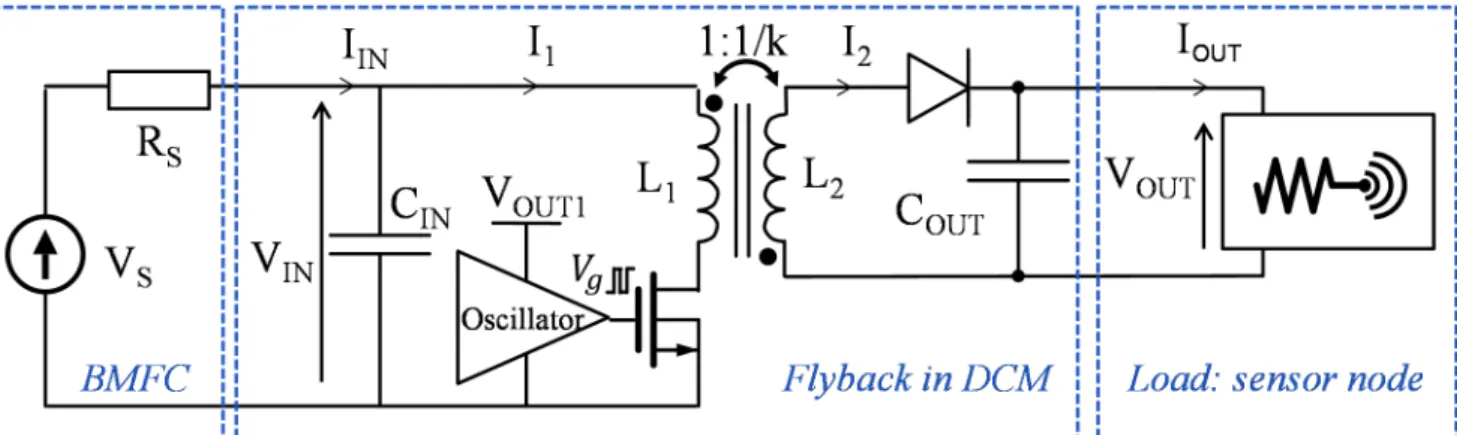
The converter shown in Figure 4. is composed of a FET transistor, diode and two coupled
coils {*+,* }. In order to simplify the implementation phase as well as the model, the same
number of turns is used for the two coils, and no snubbers were added to this system ( *+
* *). Furthermore, ,-' is added in order to supply the current peaks required by the
converter that would induce losses in the BMFC [15] and variation of the cell voltage. ,&.
allows energy to be stored and the load to be supplied. !" and /01 are sufficiently decoupled
to be considered static. The driver of the transistor is supplied by the output capacitor ,&. .
When many cells are connected in series/parallel configurations, one secondary /01+ supplies
all the drivers. A cold start is out of the scope of this circuit but some circuits have already been shown to solve start-up issues at a few 100’s of mV [16-17].
Figure 4. Converter structure
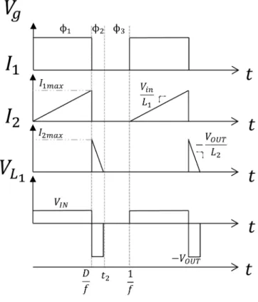
During the initial phase, 2+ as shown on Figure 5, the transistor is closed and the energy is
thus stored in the coupled coils. The current passing through the primary *+ increases. Then
during the second phase 2 , the transistor is opened. The stored energy is then released through
the only way out, i.e. the secondary inductor * . When all the energy has been released, the
diode ensures that the energy stored in ,&. returns into the coupled coils. The voltage
difference is compensated by the continuity of the current within an inductor, and the voltage across the transformer will increase until all the energy can be discharged. To calculate the losses in this converter, the average and root mean square currents passing through the elements need to be calculated.
Figure 5. Current and voltage waveforms within the flyback converter
During the first phase, the current will rise to its maximum, which is expressed by:
41 67 48∙ 9* ∙ : (2)
where D is the duty cycle and : the switching frequency of the flyback. The average and root
mean square of the current passing through the primary can then be calculated as:
41avg !"∙ 9 2 2 ∙ * ∙ : (3) 41> ? @A∙9 3 2 √3 ∙ * ∙ : (4)
During the phase 2 , as we have a unitary transformation factor (*+ * D, the peak current
,&. , G can be expressed as:
G 9: +* ∙ 4 EF
/01
(5)
The average and root mean square of the current passing through the primary can then be calculated as: 426IJ !" 2 ∙92 K#LD ∙ 2 ∙ * ∙ : (6) 42> ? 9 ∙ 48D 3 2 : ∙ * ∙M3 ∙ K#LD (7)
The impedance seen by the fuel cell can be calculated using the average current absorbed by the primary, and then expressed as:
!" 4 !" +F(N
9 2*:
(8)
During all our analyses and experiments, the duty cycle is always be set to work at the MPPT. The latter can then be expressed as:
9 O2 ∙ * ∙ : (9)
2.3 Air-coupled coils
Conventionally, magnetic material is used for the core of a transformer in order to increase the magnetic permeability of the space used for the magnetic field. The latter allows the coupling, inductivity and since it channels the magnetic flux, the electromagnetic compatibility and interference of the system to be increased. However, such a core may saturate and produce
hysteresis losses, created by the movement of the domain walls within the material and eddy current losses due to the conductivity of the core. It is difficult to take these losses into account but they can be characterized by the magnetization curve. In previous work described in [18], we highlighted the substantial losses created by the magnetic core. To completely eliminate them, the present work will use an air-core transformer. On the seabed, the BMFC surface is around a few 10’s of cm² and is working far from other electronic components. Therefore, the space used as well as the electromagnetic compatibility are of minor importance, leading to the possibility that would not be realizable in another context. The substantial area required for the electrodes can be wisely used for the transformer. However, as shown in Figure 6, cuts need to be made within the electrode so as to avoid the potential losses created by eddy currents. Previous work was done with a flyback working with a PCB printed air-core transformer [19], whereas the work presented here is done with decades larger transformers.
Figure 6. Principle of the coreless converter associated with the fuel cell
cm-scale
cm
-s
ca
2.4 Design of the converter
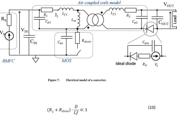
In order to design the transformer, we replaced the elements by their simplified models, see figure 7. The behavior is simulated with analytical equations so as to dimension the transformer. The previously established equations (2) to (9) for the currents are modified by the resistivity of the elements. However, as long as equation (10) is respected, we consider that the current waveforms are not significantly modified.
Figure 7. Electrical model of a converter.
1+ P?QAD ∙ 9*: ≪ 1 (10)
The equivalent model of the transformer is based on the one given in [20]. The capacitances
,S+ and ,S are created by the parasitic coupling between the windings. These are charged and
during their cycles, the average power lost during one cycle can be calculated as
The leakage inductors *V+ and *V are created by the magnetic flux generated by one coil that does not pass through the second one. The latter stores the energy which is wasted. The resistivity of the transformer also causes losses. Finally, the total losses produced by the transformer can be expressed as:
G>6A?:Q 2∙ 42> ?2 + 1∙ 41> ?2 + :2∙*:1∙ 41 672 + :2∙*:2∙42 672 (12)
The diode also produces losses. Indeed, the parasitic capacitance ,W-& stores energy which is
wasted, while the threshold voltage as well as the dynamic resistance W are as well
responsible for some losses. Those produced by the diode can then be expressed as follows:
P@QPX P∙ 41> ?2 + P∙ 42avg+ : ∙ ,P@Q∙ K#L+ G+ 48D2+ Y FZFN (13)
where Y FZFN is the power loss due to the leakage current of the diode.
Y FZFN < 4\∙ &. + -'D (14)
It is important to note that when ]
V ≪ G where G is the recovery time, it is not necessary to
take into account this phenomenon. However, for other cases at high frequency, this phenomenon can create significant losses and in several cases, justifies the use of snubbers.
Finally, if we also take into account the losses in the fuel cell, we can calculate the maximum achievable output power as;
&. -'− W-&W − E& − F' V&− %FSF
(15)
As the driver is supplied by the output, the losses generated by the transistor command, due to the consecutive charge and discharge of the transistor’s gate capacitance, should also be taken into account. They can be expressed as;
TQ 6APX ,J?∙ TQ2 6AP: (16)
where ,N is the equivalent gate capacitance of the FET. Finally the system has been
simulated with Spice equivalent models given by the manufacturer and results fit the aforementioned equations..
2.4.1 Calculation of the model of the air coupled coils.
In order to design the converter, the electric model of the transformer can be calculated analytically. Circular loops are used as this allows the highest quality factor. As explained in [21], the inductivity of a circular loop can be approximated using:
*- 8 ∙ _`∙ 2 ∙ lnc8 ∙ R
e- f − 2D
(17)
where R is the average radius of the loops, N the number of turns, e- the wire radius and
_` the magnetic permeability of the middle 1.26 µH/m for the air and water.
The resistivity + and of the transformer coils can be expressed as;
- g ∙ 2 ∙ h ∙ ∙ 8h ∙ e-
(18)
As the distance between the coils is negligible compared to the coil diameter, the coupling is very difficult to approximate analytically. Therefore, based on previous characterizations, the
coupling k has been empirically fixed at 0.95. *V- and *Ecan then be calculated as *
V-1 − iD*- and *E iM*+* .
The parasitic capacitance between the wires is almost impossible to estimate analytically as it depends on the wire position, and cross-section, and the thickness of the isolation layer. As these significantly impact the losses, the capacitances were overestimated by considering them
proportional to the number of turns N and also that the wires have square cross-section. Finally, these capacitances can be estimated as:
,S+ Ck ,&∙ 8 − 1D
,& l ∙ h ∙ 2 ∙ LℎV-Y∙ V-Y+ 2 DD - &
(19)
where Lℎ- & is the insulation thickness between the wires. At the desired working frequencies,
these wires do not have a significant effect, and therefore, the proposed model does not take into account the skin and current-crowding effect in the transformer. Indeed, these phenomena simply cannot be estimated analytically.
2.4.2 Model of the active components
The transistor gate driver is supplied by the output capacitance ,&. and so the FET transistor
has to have a threshold voltage lower than 2V. In order to minimize the losses created by the active components, a transistor with a subsequently low gate capacitance was chosen. The drain to source on-state resistance appears to be a less significant criterion as the losses are mainly created by the transistor command. Based on this, an FDV301N was chosen. In addition, based
on the datasheet [22], we determined that ,N =9.5pF and W &' 4 Ω. The on-state resistivity
of the diode appears to be much less significant than the diode threshold voltage, and
consequently a BAT54 was chosen. This allows us to have =240mV, W=5.6 Ω, ,W-& 10Up
and a leakage current of 0.05 µA [23]. 2.5 Simulation
Now that we can calculate each element of the converter, the effect of the transformer design
can be defined. For each design, the optimal frequency :&S was chosen in order to maximize
by the recovery time, parasitic coupling and the skin effect within the transformer. In order to design the air-coupled coils the effect of the number of turns and radius was simulated.
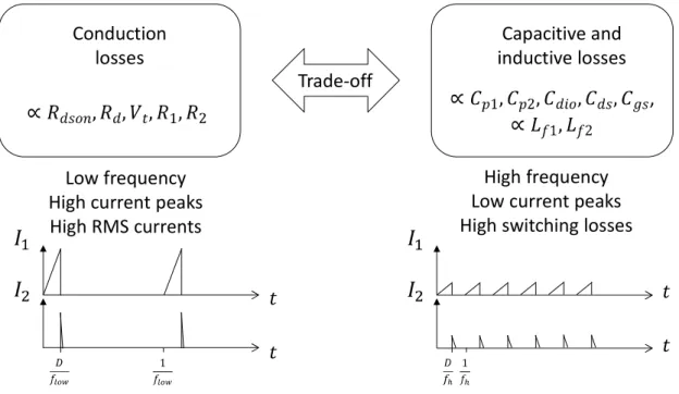
In order to understand the behavior, as shown in Figure 8, a clear distinction was made
between the conductivity losses due to W &', W, , +, and the capacitive and inductive
losses created by the charge and discharge of ,S+, ,S , ,W-&, ,W , ,N and *V+, *V , which are
proportional to the frequency. At a given frequency, too few turns would decrease the inductivity. As a consequence, this would increase the current peak given by (2) and raise the root means square value of the currents calculated with (4) and (7) , increasing the conductivity. On the contrary, too many turns and the resistivity of the transformer wires given by (18) as
well as the capacitances ,S+ and ,S , given by (19) would increase with the losses they
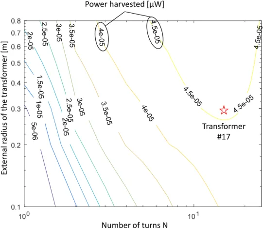
produce. Increasing the frequency allows the root mean square values of the currents to be decreased and, as a consequence, reduce the conductivity losses, but at the cost of raising the capacitive losses. As shown on Figure 9, for a radius of 0.3m, the optimal design appears to be 17 turns. This transformer will henceforth be called #17.
Figure 8. Trade-off between the conduction losses and capacitive and inductive losses
Capacitive and inductive losses , Conduction losses Low frequency High current peaks High RMS currents
High frequency Low current peaks High switching losses Trade-off
Figure 9. Simulation of the transformer design
Thanks to the above model, the losses can be analyzed closely. Based on transformer #17, we can determine the effect of varying different parameters. For instance, reducing the radius of the wire by a factor of 5 only decreases the power transferred by 0.03 µW. Also, using a coupling of 0.97 instead of 0.955 allows us to transmit 3.5 µW. In addition, by designing the transformer with particular care, for example, twisting the primary and secondary, the coupling can be increased, which thus significantly improves the harvested power. This coupling can also potentially be improved with a single-turn transformer. One with a radius of 5.5m should allow us to transfer the same amount of power with a coupling of 0.99. Therefore, a second prototype called #1 was also made to validate the model accuracy.
5 e -0 6 1 e -0 5 1 .5 e -0 5 2 e -0 5 2 e -0 5 2 .5 e -0 5 2 .5 e -0 5 3 e -0 5 3 e -0 5 3 .5 e -0 5 3 .5 e -0 5 4 e -0 5 4 e -0 5 4.5 e-0 5 4.5e -05 4 .5e -0 5 4 .5 e -0 5 ra d iu s o f th e t ra n sf o rm e r Transformer #17 E xt e rn a l ra d iu s o f th e t ra n sf o rm e r [m ] N Power harvested [µW] Number of turns N
3
E
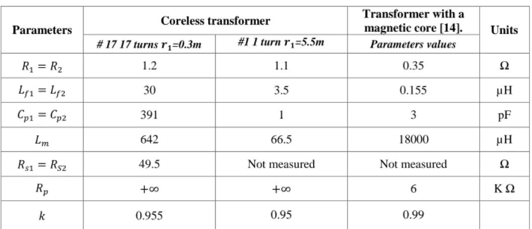
XPERIMENTAL RESULTSBased on the developed optimization algorithm, transformers #17 and #1 have been realized and characterized. The results are given in Table 1. Contrary to the expected performance, the 1-turn transformer did not exhibit a higher coupling.
TABLE 1. Characterized transformers
Parameters Coreless transformer
Transformer with a
magnetic core [14]. Units
# 17 17 turns qr=0.3m #1 1 turn qr=5.5m Parameters values
+ 1.2 1.1 0.35 Ω
*V+ *V 30 3.5 0.155 µH
,S+ ,S 391 1 3 pF
*E 642 66.5 18000 µH
+ s 49.5 Not measured Not measured Ω
S +∞ +∞ 6 K Ω
i 0.955 0.95 0.99
The experimental setup used in order to realize the measurements is shown in Figure 10. The
experiment was done with a 20 cm² MFC mimicked by a Thevenin generator Vvw 0.6 , R
1.3 kΩ). Theoretically, the maximum power calculated using (1), is equal to 69.2 µW. With
transformer #1 and a 2 V output voltage, 24 µW was transferred at 7kHz whereas with transformer #17, 43.2 µ W was transferred at 5 kHz. The global efficiency achieved is 60 % which, for the same input voltage, is close to the 70% achieved by the BQ25570 of Texas instrument which in addition does not provide any isolation. Our previous work, presented in [14], achieved 71% efficiency with a core transformer. However, as explained extensively in the next section, the coreless converter can be subsequently improved with an optimal design of the active components. These results match the model behavior with less than 1% and 7% error for transformer #17 and #1, respectively.
Figure 10. Experimental setup with transformer #17
As seen in Table I, the coreless transformer # 17, the magnetizing inductor value is 28 times lower and the leakage inductor value 200 times greater than the one with a magnetic core. On the one hand, as the magnetizing inductor value is substantially lower at the same frequency, a much smaller duty cycle is used. The current peaks given by (1) are then significantly increased from 1.2mA for the transformer with a magnetic core to 6.2mA for the coupled coils. In addition, the conduction losses are significantly increased as the winding is 3.5 times more resistive and so the RMS current is 2 times higher. Theoretically, these losses increase from 0.6µW for a classical transformer to 3.8µW for the coupled coils. On the other hand, the latter completely remove the magnetic core losses. The current passing through the coupled coils is not limited by the saturation of the magnetic material, and thus the surface of the MFC can be increased without having to adapt the transformer. As the duty cycle is extremely low (< 10%), a transformer with multiple primary coils and only one secondary one can be used. Such a structure would substantially minimize the number of components and copper used. A comparison given in Figure 11 of the previous work and this, allows us to see that the losses have been transferred from the transformer to the active components.
Coupled coils
2*17 turns
Generator
replacing the
BMFC
Active components,
Driver and
Capacitances
Figure 11. Comparison between this work with the air transformer # 17 and previous work [14] with magnetic materials
4
IMPROVEMENTS COMING FROM THE ACTIVE COMPONENTSBased on the validated modeling, we can investigate the losses created by the active components. Concerning the diode, a threshold voltage of 0.3V instead of 0.2V increased the
losses by 2 µW. This parameter has to be kept as low as possible. However, an W &' or an
W (seen in Figure 7) which is four times lower, would increase the power transmitted by up
to 3 µW. The resistivity of the diode can be reduced by adding another diode in parallel at the cost of doubling the parasitic capacitance and the leakage current. As a consequence, the optimal working frequency for the whole system is decreased when diodes are added. The same strategy could be applied to the transistor. For example, using several transistors in
parallel would decrease the W &' at the cost of increasing the capacitive losses generated by
the latter. The effects of this have been simulated, and the numerical results are given in Figures 12 and 14 for the transformers #17 and #1, respectively.
Figure 12. Power harvested with transformer #17 with several diodes/ FET configurations
Figure 13. Losses analysis, obtained by simulation, at the optimal working point of several FET and diodes configurations with
transformer #17.
#17_1=1FET/1diode, #17_2= 4FETs/5diodes, #17_3= 10FETs/10diodes
As can be seen in Figure 12, the experimental setup #17_1 can be greatly improved by adding several diodes and FET’s in parallel. With this procedure, the optimal frequency decreases as it allows fewer conduction losses at the cost of increasing the capacitive losses. With such a structure, a gain of 6µW can be obtained. As shown in Figures 13 and 15, the capacitive losses increase with the frequency and number of diodes and FET’s placed in parallel. However, having several active elements in parallel allows the conduction losses to be decreased at the cost of increasing the leakage current of the equivalent diode. Changing the
active components therefore allows more freedom in transformer design, and potentially better performance. New technologies and specifically designed components may possibly substantially decrease the conduction losses they produce without affecting the capacitive losses, thus allowing the use of smaller magnetizing inductances, and at the same time decreasing the conduction losses as well as the capacitive ones generated by the transformer. By integrating the driving circuit and the active components, the latter can be specifically chosen to maximize the harvested power.
Figure 14. Effect of the number of reactive components in parallel on the power harvested with air coupled coils #1
As transformer #1 is 9 times less inductive than #17, its RMS current is significant, leading to important conduction losses in the passive elements. By parallelizing the active components and using 5 diodes and 4 FET’s a substantial gain of 16 µW can be achieved. The latter can also be achieved by selecting other components, taking the lowest possible for the diode and then optimizing the conduction and capacitive losses generated. The same logic should be apply to select a transistor that exhibits a threshold voltage below 2V. Obviously, the optimal
transformer design as well as the optimal working frequency are linked with the active components chosen.
Figure 15. Losses analysis, obtained by simulation, at optimal working point of several FET and diodes configurations with the
transformer #1.
#1_1=1FET/1diode, #1_2= 4FETs/5diodes, #1_3= 10FETs/10diodes
5
C
ONCLUSIONIn this paper, a coreless transformer-based electrical harvesting interface for microbial biofuel cells has been designed and realized. An analytical model was proposed and validated through Spice simulation and experimentation. A coreless transformer design maximizing the power harvested was then proposed based on the suggested model.
The use of an air-core allows the magnetic losses and saturation constraint to be removed. Our prototype achieves 60% efficiency for an output power of 43 µW. Simulations have proven that this result can be improved by up to 50µW by changing the active components. The proposed converter can subsequently be improved by a global optimization taking into account the active components as well as the transformer, while keeping in mind that the optimal choice of one component is substantially affected by the others. Further research has now to be done regarding the magnetic field interactions with sea water.
R
EFERENCES[1] S. Ulukus, A. Yener, E. Erkip, O. Simeone, M. Zorzi, P. Grover and K. Huang, “Energy Harvesting Wireless Communications: A Review of Recent Advances,” IEEE Journal of Sel. Areas in Comm., (2015), vol. 33, no. 3, pp. 360-381.
[2] C. Alippi and C. Galperti, “An Adaptive System for Optimal Solar Energy Harvesting in Wireless Sensor Network Nodes,” IEEE Trans on Circuits and Systems, (2008), vol. 55, no. 6, pp. 1742–1750.
[3] V. Raghunathan, A. Kansal, J. Hsu, J. Friedman, and M. B. Srivastava, “Design considerations for solar energy harvesting wireless embedded systems,” in Proc. 4th Int. Symp. IPSN, (2005), pp. 457–462.
[4] G. K. Ottman, H. F. Hofmann, A. C. Bhatt, and G. A. Lesieutre, “Adaptive piezoelectric energy harvesting circuit for wireless remote power supply, ” IEEE Trans. Power Electron., (2002), vol. 17, pp. 669–676.
[5] A. Morel, G. Pillonnet and A. Badel, “Regenerative synchronous electrical charge extraction for highly coupled piezoelectric generators, ”, in Proc. IEEE 60th International Midwest Symposium on Circuits and Systems (MWSCAS), (2017), pp 237-240.
[6] X. Lu and S.-H. Yang, “Thermal energy harvesting for WSNs,” in Proc. IEEE Int. Conf. Syst. Man Cybern., (2010), pp. 3045–3052.
[7] M. Ashraf and N. Masoumi, “A thermal energy harvesting power supply with an internal startup circuit for pacemakers,” IEEE Transactions on VLSI Systems, (2016), vol. 24, no. 1, pp. 26–37, 2016.
[8] H. Wang, J.-D. Park, Z.J. Ren, “Practical energy harvesting for microbial fuel cells: a review, ” Environ. Sci. Technol., (2015), vol. 49, pp. 3267-3277.
[9] T. Chailloux, A. Capitaine, B. Erable, G. Pillonnet., “Autonomous sensor node powered by cm-scale benthic microbial fuel cell and low-cost and off-the-shelf components,” Energy Harvesting and Systems EHS, (2016), vol. 3, pp. 205-212.
[10] N. Degrennet, B. Allard, F. Buret, S. Adami, D. Labrousse, C. Vollaire,F. Morel., “A 140 mV self-starting 10mW DC/DC converter for powering low-power electronic devices from low-voltage microbial fuel cells,” J. Low Power Electron., (2012), vol. 8, no. 4, pp. 485-497.
[11] A. Meehan, G. Hongwei, and Z. Lewandowski, “Energy harvesting with microbial fuel cell and power management system,” IEEE Trans. Power Electron., (2011), vol. 26, no. 1, pp. 176–181.
[12] F. Khaled, B. Allard, O. Ondel, C. Vollaire, “Autonomous Flyback Converter for Energy Harvesting from Microbial Fuel Cells,” Energy Harvesting and Systems, , DE GRUYTER, vol. 3(2), 2016.
[13] F. Khaled, O. Ondel, and B. Allard, “Optimal Energy Harvesting From Serially Connected Microbial Fuel Cells, ” Ieee Trans. Ind. Electron., (2015), vol. 62, 3508–3515.
[14] A. Capitaine, G. Pillonnet, T. Chailloux, F. Khaled, O. Ondel and B. Allard, “Loss analysis of flyback in discontinuous conduction mode for sub-mW harvesting systems,” in Proc. of IEEE 14th International New Circuits and Systems Conference (NEWCAS), (2016), pp. 1-4.
[15] A. Capitaine, G. Pillonnet, T. Chailloux, A. Morel and B. Allard, “Impact of switching of the electrical harvesting interface on microbial fuel cell losses,” 2017 IEEE SENSORS,
Glasgow, 2017, pp. 1-3.
[16] J. Goeppert and Y. Manoli, “Fully integrated start-up at 70 mV of boost converters for thermoelectric energy harvesting,” IEEE J. Solid-State Circuits, (2016), vol. 51, no. 7, pp. 1716–1726.
[17] T. Martinez, G. Pillonnet and F. Costa, “A 15 mV Inductorless Start-up Converter Using a Piezoelectric Transformer for Energy Harvesting Applications, ” IEEE Transactions on Power Electronics, vol. 33, no. 3, pp. 2241-2253, 2018.
[18] Y. Wanderoild, A. Capitaine, A. Morel and G. Pillonnet,“100 μW Coreless Flyback Converter for Microbial Fuel Cells Energy Harvesting, ” in Proc. of IEEE New Generation of Circuits and Systems (NGCAS), (2017), pp. 33-36.
[19] A. Bouabana, C. Sourkounis, and M. Mallach, “Design and analysis of different structure of a coreless planar transformer for a flyback converter,” in 2012 International Symposium on Power Electronics, Electrical Drives, Automation and Motion (SPEEDAM), (2012), pp. 827–831.
[20] Y. Wanderoild, D. Bergogne, and H. Razik, “High Frequency, High Temperature designed DC/DC Coreless Converter for GaN Gate Drivers,” in PCIM Europe 2016; International Exhibition and Conference for Power Electronics, Intelligent Motion, Renewable Energy and Energy Management, (2016), pp. 1–7.
[21] L. Bettaieb, F. Costa, and J.-C. LOURME, “Transmission d’énergie par couplage inductif. Application aux capteurs biomédicaux intégrés,” in Symposium de Génie Électrique 2014, Cachan, France, 2014.
[22] Fairchild Semiconductor, “FDV301N Digital FET, N-Channel,” FDV301N datasheet, June 2009.
[23] Vishay, “Small Signal Schottky Diodes, Single and Dual,” BAT54 datasheet, Rev. 1.9, 2016.
B
IOGRAPHIESYohan Wanderoild was born in Grenoble, France, in 1991. He received his Master’s of science in electronics, electrical energy and automated control as part of the ENS Paris Saclay degree in 2015. He is currently a PhD candidate in the CEA-LETI, France. His research interests are focused on power electronic circuits and systems.
Adrien Morel was born in Valenciennes, France, in 1993. He received his electrical engineering degree from the National Institute of Applied Sciences of Lyon (INSA Lyon) and his MSc degree in integrated systems from the University of Lyon, both in 2016. He is currently pursuing his PhD at CEA Leti in Grenoble, France. His research interests focus on micro-energy harvesting, multi-physics interactions, integrated power management, and ultra-low-power analog circuit design.
Armande Capitaine was born in Brest, France, in 1991. She received her electrical engineering degree and her M.Sc degree in nanotechnologies from the National Polytechnic Institute (PHELMA - INPG) in Grenoble in 2014. She followed international studies by working at Federal Institute of Technology in Lausanne (EPFL), Switzerland, and at the
Politecnico di Torino, Italy. She received her Ph.D at CEA Leti in Grenoble, France, in electronics in 2017. Her research project deals with energy harvesting from benthic microbial fuel cells.
G. Pillonnet was born in Lyon, France, in 1981. He received his Master’s degree in Electrical Engineering from CPE Lyon, France, in 2004, a PhD and habilitation degrees from INSA Lyon, France in 2007 and 2016, respectively. Following an early experience as analog designer in STMicroelectronics in 2008, he joined the University of Lyon in the Electrical Engineering department. During the 2011-12 academic year, he held a visiting researcher position at the University of California at Berkeley. Since 2013, he has been a full-time researcher at the CEA-LETI, a major French research institution. His research focuses on low-power electronics using heterogeneous devices including modeling, circuit design and control techniques. He has published more than 70 papers in his areas of interest.
View publication stats View publication stats