Design of Fluid Film Journal Bearings Containing Continuous 3D Fluid Pathways which are Formed by Wrapping a Sheet Containing 2D Through-Cut Features
by
Amos Greene Winter, V B.S., Mechanical Engineering (2003)
Tufts University
Submitted to the Department of Mechanical Engineering in Partial Fulfillment of the Requirements for the Degree of
Master of Science in Mechanical Engineering at the
Massachusetts Institute of Technology June 2005
C 2005 Massachusetts Institute of Technology All rights reserved
Signature of Author... ...
Department of Mechanical Engineering May 8, 2005
C ertified by ... . V.., .W ... ... . ... Martin L. Culpepper Ro well International Assistant Professor of Mechanical Engineering
A Thesis Supervisor
Accepted by ... ... Lallit Anand Chairman, Department Committee on Graduate Students
ARCHIVES
Page 1
OF TECHNOLOGY
NOV 0 7 2005
LIBRARIES
Design of Fluid Film Journal Bearings Containing Continuous 3D Fluid Pathways which are Formed by Wrapping a Sheet Containing 2D Through-Cut Features
by
Amos Greene Winter, V
Submitted to the Department of Mechanical Engineering on May 8, 2005 in Partial Fulfillment of the Requirements for the
Degree of Master of Science in Mechanical Engineering ABSTRACT
The purpose of this research was to generate the knowledge required to: (1) design and manufacture fluid film bearings that do not require precision machining processes during fabrication, but rather gain their precision from off-the-shelf parts used in the fabrication process and (2) manufacture parts with 3D internal networks by wrapping thin sheets of material containing 2D through-cut features. This wrapping-based fabrication process, called Three-Dimensional Wrapped Network (3DWN) technology, uses the precision of low-cost, ubiquitous items instead of manufacturing processes to meet the precision requirements of hydrostatic bearings. 3DWN bearings are fabricated by cutting 2D through-cut features into shim stock and then wrapping the shim stock around a precision mandrel. The 2D shim stock features are designed such that they align and form 3D internal networks within the bearing during wrapping. In the final wrapped structure the bore retains the precision diameter of the mandrel and the surface finish of the shim stock, thus meeting the functional requirements of the bearing.
This thesis investigates the design and manufacturing of 3DWN hydrostatic bearings. An analytical model was derived to describe the transformation of 3D cylindrical features to 2D through-cut features. Conventional hydrostatic designs and theory were adapted for use in 3DWN bearings. A proof-of-concept was designed, constructed, and tested. Although contact between the shaft and bore was observed during testing, the fluid film stiffness matched theory within 1.6% after accounting for the contact stiffness. The mean bore diameter was measured to be within 0.03% of the mandrel diameter with errors that lie within 5G of the tolerable error range in the front of the bearing and 2u in the rear. In a comparison with a conventional hydrostatic bearing of the same size and surface design, the 3DWN cost lOX less.
Thesis Supervisor: Martin L. Culpepper
Title: Rockwell International Assistant Professor of Mechanical Engineering
BIOGRAPHICAL NOTE
Amos Greene Winter, V was born November 29, 1979 in Peterborough, NH. From Feb -June 2002, he attended the University of Canterbury in Christchurch, NZ. As part of this semester abroad, he road his motorcycle through both islands in NZ and solo through the Australian Outback. He graduated magna cum laude from Tufts University in May 2003 with B.S in Mechanical Engineering. Starting in the fall of that year, he enrolled in the Massachusetts Institute of Technology and joined the Precision Compliant Systems Lab (PCSL). This thesis is the culmination of his research in the PCSL. During his masters' degree, Amos Winter published two conference articles: "Fluid film bearings requiring no precision machining processes, formed by wrapping 2D sheets." ASPE 19th Annual
Meeting 2004 and "Design of a gimbaled compliant mechanism stage for precision motion and dynamic control in Z, OX & OY directions." ASME DETC 2004. The work presented in this thesis is currently being prepared for publication in Precision Engineering.
ACKNOWLEDGMENTS
First and foremost I would like to thank Prof. Martin Culpepper for hiring, funding, and allowing me pursue a project of my own conception. Thank you for striking the educational balance between advising, motivating, mentoring, and giving me the freedom to make many discoveries and mistakes on my own. You have made a profound impact on my life, and I look forward to many fun years ahead during my PhD.
Next, I'd like to thank my labmates Spencer Szczesny and Nate Landsiedel for becoming two of the greatest friends I have ever made, and supporting me through good times and bad during my masters. I would also like to thank my other labmates Dariusz Golda, Shih-Chi Chen, Kartik Mangudi, Soohyung Kim, Rich Timm, Kevin Lin, and Patrick Carl for your help and support.
The people with whom I am closest in my personal life deserve many thanks. Thank you Anne, for being so much more than my girlfriend by also being my best friend. Thank you mom, Lilly, Aunie, and Darlene for your support and encouragement, and providing a place to getaway and relax. Thank you Alex and Signe, my two lifelong friends who have had a continuous impact on my life since elementary school. Also I want to thank Abby, Katie Y, Brian, Chuck, Katie N, John, and Hong for your friendship.
I'd like to recognize the many professors, students, engineers and technicians who added immense amounts to my education. Thank you Prof. Alex Slocum, Prof. Samir Nayfeh, Prof. Tim Gutowsky, Mark Belanger, Jerry Wentworth, Maggie Sullivan, Jason Pring, John Kane, Gil Pratt, for your technical, educational, and inspirational guidance.
Finally on a less serious note, I would like to thank all the people and things that helped keep me sane through these last two years: My tortoise Nomar, Dave Chappelle, John Stewart, Jerry Seinfeld, the Boston Red Sox, and my motorcycle.
TABLE OF CONTENTS
A B ST R A C T ... 3 BIOGRAPHICAL NOTE...5 ACKNOWLEDGMENTS...7 TABLE OF CONTENTS...9 L IST O F FIG U R E S ... 14 L IST O F T A B L E S ... 17 1 IN TR O D U C T IO N ... 19 1.1 M otiv ation ... 241.2 Research Purpose, scope and summary of results...27
1.2.1 Questions to be answered in research ... 28
1.2.2 Research tasks performed... 28
1.2.3 Scholarly contribution of research ... 29
1.2.4 Summary of results... 30
1.3 Thesis O rganization ... 31
2 BACKGROUND ... 32
2.1 H ydrostatic bearings ... 32
2.1.1 How hydrostatic bearings support a load... 32
2.1.2 Modeling bearing flow... 34
2.2 Verification of flat plate assumption in journal bearings... 36
2.3 Means of fluid restriction... 38
2.4 Surface self-compensated bearings ... 39
3 3DWN BEARING DESIGN... 43
3.1 Inception of 3DWN technology ... 43
3.2yp ... . 4 5 3.3 Motivation to design a HBP... 45
3.4 Satisfying precision requirements of the HBP... 46
3.4.1 Characterization of surfaces... 47
3.4.2 Satisfying surface finish requirements ... 48
3.4.3 Satisfying bore diameter and roundness requirements... 49
3.5 Design of 3DWN HBP bore surface features ... 49
3.5.1 Inspiration for HBP surface feature design...50
3.5.2 HBP pad configuration... 51
3.5.3 Overlap region of bearing bore ... 53
3.5.4 R estrictor design ... 54
3.5.5 Full 3DWN HBP bore feature design ... 56
3.6 Design of Internal Channels...57
3.6.1 2D through-cut parameters...58
3.6.2 Design of HBP fluid networks for low resistance... 59
3.6.3 Feed channel design ... 59
3.6.4 Cross-connection channel design... 59
3.6.5 Drainage channel design ... 60
3 .7 S um m ary ... 60
4 MODELING AND ANALYSIS... 61
4.1 W rapping m odel... 61
4.1.1 Describing a wrapped structure...61
4.1.2 3D to 2D coordinate transformation ... 65
4.2 Modeling bearing performance...70
4.2.1 Fluid resistance modeling ... 70
4.2.2 R esistance ratio ... 72
4.2.3 Derivation of effective pad area...73
4.2.4 Derivation of bearing stiffness...75
4.3 Sensitivity A nalysis... 76
4.3.1 Justification for using non-precision cutting processes ... 76
4.3.2 Sensitivity of performance to internal channel errors ... 78
4.3.3 Justification for neglecting tension in the wrapping model ... 80
4.3.4 Sensitivity to bore bulge to channel placement... 81
5 MANUFACTURING A 3DWN HBP... 84
5.1 Failed attempts at adhering wrapped layers ... 84
5.2 Template fabrication ... 86
5.2.1 Waterjet cutting... 86
5.2.2 Fixturing of Template within waterjet ... 87
5.3 Template wrapping ... 87
5.3.1 R olling jig ... . 87
5.3.2 Alignment of Template to mandrel... 88
5.3.3 Adhesion of wrapped layers...90
5.4 Packaging the Template in a housing... 91
5.4.1 Joining Template and housing...91
5.4.2 Prepping the HBP for casting... 92
5.4.3 Casting the Template into the housing...93
5.4.4 Finishing procedures.. ... 94
5.5 Summary ... ... 95
6 EXPERIMENTAL VERIFICATION .. ... 96
6.1 Experimental setup ... 96
6.5.1 Parameters of the 3DWN HBP used in experimentation ... 96
5.1.2 Experimental setup for stiffness testing ... 98
5.1.3 Bore measurement...99
5.2 Stiffness results and discussion... 100
5.2.1 Stiffness test results... 100
5.2.2 Sources of error in stiffness data... 101
5.3 Results from bore measurements... 104
5.4 C ost com parison ... 104
5 .5 S um m ary ... 105 7 SU M M A R Y ... 106 7.1 Scholarly Contributions...106 7.2 Engineering impact ... ... 107 7 .3 F uture w ork ... 10 8 Page 11
LIST OF FIGURES
Figure 1.1 3DWN bearing manufacturing process ... 21
Figure 1.2 Precision requirements decoupled from fabrication of the bearing ... 22
Figure 1.3 Finished 3DW N bearing ... 23
Figure 2.1 Configurations and pressure profiles for different bearings ... 33
Figure 2.2 Fluid relationships in hydrostatic bearings ... 34
Figure 2.3 Velocity profile of fully developed flow ... 34
Figure 2.4 Bearing eccentricity during shaft displacement... 37
Figure 2.6 HydroglideTM surface self-compensated bearing [1]...41
Figure 2.7 Fluid circuit for surface self-compensated bearing ... 41
Figure 3.1 Flat actuator concept and implementation...44
Figure 3.2 First 3DWN mock-up and rolling process...44
Figure 3.3 Example surface roughness profile [20]... 47
Figure 3.4 Determination of Ra value [21]... 48
Figure 3.5 Hydrostatic self-compensated journal bearing [22]...50
Figure 3.6 Annular restrictor designs for hydrostaic surface self-compensated bearings 51 Figure 3.7 Comparison of pad configurations ... 52
Figure 3.8 Chosen 3DWN HBP bore surface features layout...53
Figure 3.9 Geometric matching of overlap region...54
Figure 3.10 Single feed, double annulus restrictor configuration...55
Figure 3.11 3DWN self-compensated bearing pad bore surface features and geometric p aram eters ... 5 6 Figure 3.12 3DWN self-compensated bearing template ... 58
Figure 4.1 Diagram of overlap region of layer one and two...62
Figure 4.2 Model used for x-displacement of cantilevered beam...64
Figure 4.3 Transformation of 3D cylindrical features to Template features...66
Figure 4.4 Local coordinate system for position along cantilevered beam...67
Figure 4.5 Flow over bearing bore surface features...71
Figure 4.8 Pad stiffness configuration of HBP (gap greatly exaggerated) ... 75
Figure 4.9 Sensitivity of the HBP stiffness to manufacturing errors for h/R = .002, h/i = 0 .0 1 1 ... 7 7 Figure 4.10 Channel constriction as a result of internal feature misalignment...78
Figure 4.11 Internal channel resistance sensitivity to expected error range of t and R for t/R = 0 .0 1... . . .. 79
Figure 4.12 Error caused by wrapping tension ... 81
Figure 4.13 Bore bulge resulting from pressurized channels...81
Figure 4.14 Deflection of Template due to tension...82
Figure 4.15 FEA Results from deformity deflection under tension...83
Figure 5.1 Template being cut in waterjet ... 86
Figure 5.2 Kinematic fixture for waterjet cutting, waterjet cutting setup...87
Figure 5.3 3DW N bearing rolling jig... 88
Figure 5.4 Template mounted on rolling jig ... 89
Figure 5.5 Adhering adjacent layers within the HBP ... 91
Figure 5.6 Centering of Template within housing ... 92
Figure 5.7 Preparations for casting ... 93
Figure 5.8 Wrapped Template cast in housing... 94
Figure 5.9 Drainage ports with grease plugs removed... 94
Figure 5.10 Residual super glue to be removed from bearing bore surface features...95
Figure 6.1 Experimental setup for testing stiffness... 98
Figure 6.2 Oil pressurization device ... 99
Figure 6.3 Bore precision testing using a CMM ... 100
Figure 6.4 M easured stiffness vs. theory ... 101
Figure 6.5 View of leakage flow (shaft removed from bore) ... 102
Figure 6.6 Bearing fluid circuit including leakage flow ... 102
Figure 6.7 Theoretical stiffness with and without leaks ... 103
LIST OF TABLES
Table 1.1 Comparison of different bearing types [2]...24
Table 1.2 Hydrostatic journal bearing applications [1-3] ... 25
Table 2.1 M ethods of bearing compensation ... 39
Table 3.1 Progression of early 3DWN prototypes ... 45
Table 5.1 Failed attempts at adhering wrapped layers...85
Table 6.1 Parameters of the 3DWN HBP used in experimention... 97
Table 6.2 Measurements of bore at front and rear of bearing ... 104
Table 6.3 Cost comparison 3DWN and conventional bearing... 105
CHAPTER
1
INTRODUCTION
The purpose of this research was to generate the knowledge required to:
1. Design and manufacture fluid film bearings (FFBs) that do not require precision machining processes during fabrication, but rather gain their precision from off-the-shelf parts used in the fabrication process.
2. Manufacture parts with 3D internal networks by wrapping thin sheets of material containing 2D through-cut features.
All FFBs support a load on a pressurized film of fluid. The bearing surfaces have to be precise in their spacing and surface finish to insure uniform film properties and to insure no mechanical contact between bearing components. Traditional FFBs require precision machining processes to provide the requisite geometric accuracy and surface finish. Additionally, fluid static bearings require internal networks to distribute fluid throughout the bearing. Current FFBs have the following drawbacks which limit their use in widespread engineering applications:
" Precision machining processes used to make the bearing surface contribute significantly to the overall cost of the bearing.
" Fluid networks have to be machined or cast into the bearing, which adds extra labor time, manufacturing steps, and cost to the bearing.
" Fixed restrictor bearings require tuning for optimum performance (means of restriction are discussed in a later section), adding further labor time and effort during bearing installation.
" Self-compensated bearings, which self-tune and can achieve twice the stiffness of fixed restrictor bearings [1], require extensive internal channels which connect restrictors and pads.
The central thesis of this research is that FFBs can be fabricated with incorporated internal networks by wrapping thin 2D sheets. Further, this may be accomplished without the need for a bearing manufacturer to perform precision machining processes. This wrapping-based fabrication process, called Three-Dimensional Wrapped Network (3DWN) technology, uses the precision of low-cost, ubiquitous items instead of manufacturing processes to meet the precision requirements of the bearing. Figure 1.1 illustrates how 3DWN bearings are made.
Step Process
1 Precision surface finish
and thickness material (e.g. shim stock)
Precision diameter ground mandrel
2 Template cut into shim
stock with 2D process
(e.g. laser cutting)
Adhesive applied to back side 3 Template wrapped about mandrel Adhesive bonds each layer 3D internal 3DWN Precision features
bearing diameter from formed by
mandrel template
Precision
Figure 1.1 3DWN bearing manufacturing process
The 3DWN process begins with two off-the-shelf parts that have inherent precision:
1. A precision ground mandrel with the required diameter size, tolerance, and
circularity for the bearing
2. Cold rolled shim stock with the required surface finish for the bearing
A pattern of through-cut features is cut into the shim stock, forming a template. Adhesive
is applied to the back of the template. The features in the template are designed such that they form internal networks within the bearing when the template is wrapped. In its final form, the bearing bore retains the precision diameter of the mandrel and the surface finish of the shim stock, thus meeting the functional requirements of the bearing.
3DWN bearings can be made less expensively than conventional hydrostatic journal
bearings given that the precision requirements of the bearing are satisfied by low-cost, well-developed manufacturing processes. The chart in Figure 1.2 demonstrates how the precision of the bearing is decoupled from the fabrication of the bearing.
Total diameter errors within one-forth of
bearing gap The maximum peak-to-valley surface roughness not
greater than one-fourth the bearing gap [1,6]
Restrictors, pads, and drains
Template wrapped around precision ground mandrel, replicating mandrel diameter
Template, made from shim stock with precision surface
finish, forms bore surface
Bearing features cut into Template using 2D
through-Off-the-shelf precision ground mandrel Off-the-shelf shim stock with cold rolled precision surface finish
I, I
3DWN technology enables greater flexibility in design because many sizes of 3DWN bearings can be made with the same process. For instance, a 3DWN bearing assembly line equipped with one wrapping machine and a variety of mandrel sizes could produce multiple bearing designs and sizes. Mandrels could be re-used between bearings, which could further reduce the cost of production.
A self-compensated hydrostatic journal bearing, shown in Figure 1.3, was designed, modeled, and tested as a case study for 3DWN technology. This bearing is composed of two sets of four radial pads, which give the bearing moment and radial stiffness. The template contains all bearing features and internal fluid networking, including feed, drain, and cross channeling between the restrictors and pads. The 3DWN bearing is potted within an aluminum sleeve. In this form, the quasi-monolithic assembly is structurally
stiff. The housing allows for mounting and provides a connection to pressurized fluid.
On
Aluminum
sisleeve
Wrapped
Y
bearing
Potting
compound
A. Bearing after wrapping B. Bearing cast into an aluminum housing Figure 1.3 Finished 3DWN bearing
The bearing shown in Figure 1.3 is a proof-of-concept, and is not designed for any specific application. This thesis presents the design process, modeling, and fabrication used to make the prototype shown in Figure 1.3. The methods described may be used by engineers to design 3DWN bearings for specific applications.
Page 23 mrNWOM
1.1 Motivation
Hydrostatic bearings are utilized in applications that require high load capacity (on the order of mega Newtons), high stiffness (N/nm) [1], and low friction without stick-slip. These bearings have advantages over other types of journal bearings. A comparison of different bearing types is presented in Table 1.1. The bearings are rated 1 to 5, with high being most favorable.
Table 1.1 Comparison of different bearing types [2]
Considerations for journal bearings
Types
Characteristics Hydrodynamic Hydrostatic Rolling Elements
Design 3 3 4
Positioning accuracy 2 2 2
Assembly 3 3 2
Cost (to manufacture) 3 2 3
Cost (to install) 3 2 4
Life 3 4 3
Lubrication circuit 3 2 4
Cost of lubrication circuit 3 2 4
Supply pressure and pumping power 3 2-3d 4
Load 2-3 b 2-4 d3
Stiffness 2-3 2-4d 3
Vibration damping 2-3c 4 2
Friction coefficient and frictional power 3 3-54
A hydrostatic journal bearing uses a high pressure fluid film to support a shaft. Incompressible fluid is used and a large portion of the bearing bore is pressurized, which
shaft and the bearing bore since the shaft is completely supported on the fluid film. As a result there is no stick-slip, making the motion of the bearing highly repeatable.
Hydrostatic bearings are ideal for applications where high load capacity, high stiffness, and low friction are needed. Unlike hydrodynamic bearings, hydrostatic bearings do not require a spinning shaft to maintain their load-bearing properties. As such, they have excellent performance in stationary and stop-start operation. Table 1.2 lists specific
applications and benefits of hydrostatic journal bearings.
Table 1.2 Hydrostatic journal bearing applications [1-3]
Hydrostatic
journal
bearing applicationsCategories Specific applications
IBenefits
Large machines
Medium sized machines
Telescopes Radio telescopes Radar antennas
Air reheaters for boilers Rotating mills for ores or slags Iarge boring machines
Large milling machines Large lathes Assembly lines Large structures i -Grinding machines CNC machining centers
Medium-high velocity spindles Precision balances
High load capacity No wear
Precision rotation Squeeze film damping High stiffness
No stick-slips
Lubricated while stopped No wear
Hydrostatic journal bearings offer better performance than other types of bearings. However, there are factors that make them undesirable for some applications:
* Bore machining cost: Traditional hydrostatic journal bearings require a precision process to machine the bore to the required diameter and surface finish.
* Fluid channel machining cost: Hydrostatic bearings require fluid to be injected into multiple locations between the bore and shaft. Distribution of fluid requires an internal network system around the bearing.
" Added machining for self compensation: Self compensating bearings offer higher load capacities and stiffness than fixed compensator bearings, but require additional fabrication to produce cross-linked fluid pats for restrictors and pads.
" Custom design and low production volume: Hydrostatic bearings can vary in and size and surface feature layout, requiring most designs to be customized and made in small numbers.
Methods have been employed to lower the cost of producing hydrostatic journal bearings, yet all of these require at least one precision machining process. Self-compensated hydrostatic journal bearings, made by Kotilainen, et al. [4,5], were formed by sand or investment casting. Although these bearings require fewer manufacturing steps than conventional FFBs, the bore requires post-casting precision machining post and the molds are destroyed during production, which further adds cost.
Kotilainen's cast bearings are a spin-off from a reduced-cost technology, the TurboToolTM and HydroSpindleTM [6-9], which have the bearing features cut into the shaft instead of the bearing bore. These technologies still require 3D machining and precision grinding of the shaft. Another method of making hydrostatic bearings is by pressing bronze sleeves into a block. In this process the bore has to be post machined to compensate for the press fitting [10]. Also, Babbitting, where molten metal is cast around a conical shaft, has been used for decades to make replicated bores, but this process also requires finish machining [10, 11]. Polymers have been through-cut with a bearing bore
surface features and adhered to bearing bores [Lyon patent], but this process requires the bore to be machined to same diameter precision as a conventional hydrostatic bearing.
Kotilainen's research demonstrates that an imprecise process such as casting may be used to make the bearing bore surface bore surface features without adversely affecting performance. This reduces the cost of producing these bearings below that of conventional bearings [4,5]. In a similar fashion 3DWN technology uses imprecise through-cutting processes like laser or waterjet cutting to make the bearing features. As such, the precision requirements may be met by off-the-shelf parts. The advantages of 3DWN technology in bearing manufacturing are summarized below.
* Decoupled precision: The precision requirements of the bearing are compartmentalized within the mandrel and shim stock, which are low cost and easy of others to fabricate. Cutting of the template does not require a precision process.
* Included feed channels: Bearing features and internal network features are all included in the template.
" 1-Step machining: Using 3DWN technology, the bearing features and the network features are cut in the template at the same time using the same process.
* Monolithic construction: 3DWN wrapped structures are made from one part, and may easily be potted into a housing to make a bearing.
* Flexible production: The mandrel is not destroyed during the wrapping process. Thus, a single wrapping system with multiple mandrels may make varying bearing sizes.
1.2 Research Purpose, scope and summary of results
1.2.1 Questions to be answered in research
The questions that are answered through this research are:
1. How can a cylindrical structure with internal features be modeled as a wrapped structure, and how is the wrapped structure modeled unrolled as a 2D sheet with through-cut features? What errors result that affect bearing performance result from this process?
2. How is the level of precision quantified for the off-the-shelf parts used in 3DWN bearing fabrication?
3. How are 3DWN bearings manufactured? What bearing materials, adhesives, and support structures have to be considered in implemented. What is the best method for rolling?
4. What are the practical issues regarding the design process, fabrication, and implementation of 3DWN technology to fluid film bearings?
5. How can a 3DWN bearing design be chosen for a particular application? What modeling techniques are necessary to select a 3DWN bearing design, determine its dimensions, and predict its performance?
1.2.2 Research tasks performed
1. A model to transform 3D cylindrical coordinates to 2D sheet coordinates was derived. Errors were introduced into the model and resulting sensitivity to bearing performance was analyzed.
2. Conventional bearing theory for precision requirements was used to form metrics for off-the-shelf precision parts.
3. Materials suitable to wrapping and use in the bearing were determined. Multiple adhesives were tested. Prototypes to verify manufacturing methods were built.
4. Current fluid film bearing theory and bearing feature designs were modified for use in 3DWN bearings.
5. A 3DWN bearing prototype was built and tested as a bench-level prototype.
1.2.3 Scholarly contribution of research
The following scholarly contributions are a result of the work presented in this thesis:
1. 3DWN technology is a new method of making a precision bearing bore. Surface replication by wrapping is a deviation from conventional bearing manufacturing practices; all current fluid film journal bearings require at least one precision process in their construction.
2. In the 3DWN manufacturing process the errors associated with the non-precision parts have less of an effect on bearing performance then errors in the precision parts. This is a powerful relationship, in that it supports the feasibility of 3DWN technology by showing a hydrostatic bearing's precision requirements can be decoupled from the fabrication processes used to make it.
3. Metrics to judge the level of precision required in the off-the-shelf parts used to make a 3DWN bearing are defined from conventional hydrostatic bearing theory.
4. A new method of manufacturing 3D parts with internal features by using 3DWN technology. 3DWN is not limited to fluid channels; it could be used for many kinds of applications that require cylindrical internal networks.
5. A model for describing a wrapped structure is derived. This model enables coordinates in a 3D cylindrical structure to be transformed to a 2D Template. When the Template is rolled, the 2D features align in the wrapped structure to recreate the original 3D features.
6. Existing bearing features are modified such that it can be cut into a 2D Template. Conventional hydrostatic bearing analysis is used to evaluate the bearing performance.
1.2.4 Summary of results
The final 3DWN bearing prototype designed, constructed, and tested for this thesis was a surface self-compensated hydrostatic journal bearing. The bearing had a bore surface features consists of two axial sets of four circumferentially spaced pads, each connected to an opposed surface restrictor. It was lubricated with heavy weight motor oil and pressurized with shop air regulated to a safe level (100psi) for laboratory experiment. Load capacity and stiffness were tested by applying varying loads to the shaft and measuring the eccentricity of the shaft within the bearing.
Although contact between the shaft and bore was observed, the fluid film stiffness matched theory within 1.6% after accounting for the contact stiffness. The mean bore diameter was measured to be within 0.03% of the mandrel diameter with errors that lie within 5y of the tolerable error range in the front of the bearing and 2y in the rear. In a
comparison with a conventional hydrostatic bearing of the same size and surface design, the 3DWN cost
loX
less.1.3 Thesis Organization
Chapter 2 presents a background on hydrostatic bearings, which includes modeling of bearing fluid flow and means of restriction. The third chapter describes how the concept for 3DWN bearings was conceived and how 3DWN bearings are designed. The fourth chapter presents the wrapped structure model, error functions, the use of established bearing theory in 3DWN bearings, and a cost comparison with conventional hydrostatic journal bearings. The fifth chapter describes the materials and adhesives were chosen and how 3DWN bearing prototypes were constructed. The experimental setup, testing procedure, and results are presented in the sixth chapter. Possible sources of error are also identified and verified through testing and examination. The seventh chapter provides a
summary of results and a discussion of future research.
CHAPTER
2
BACKGROUND
This chapter covers the basic theory behind hydrostatic bearings. The first section provides an explanation of how a hydrostatic bearing supports a load. The second section presents verification the flat plate model used in journal bearings. The third section describes methods of restricting bearing flow. The final section gives a background on surface self-compensated bearings.
2.1 Hydrostatic bearings
2.1.1 How hydrostatic bearings support a load
Hydrostatic bearings support a load on a thin film of pressurized fluid. The origins of these bearings can be traced to L.G. Girard, who in 1852 made the first water hydrostatic journal bearing [13]. In all hydrostatic bearings, pressurized fluid is pumped into the pad and slowly flows out over the bearing lands. The bearing gap is small enough to restrict the flow over the lands and induce a linear pressure drop from viscous losses. Depending on whether or not the bearing is pocketed, the pressure profile over the bearing surface has a triangular or trapezoidal pressure profile, as shown in Figure 2.1. A pocketed bearing has the benefit of a larger area exposed to input pressure, thus resulting in higher load capacity and stiffness
11l
P in
P
-A. Pocketed bearing B. Non-pocketed bearing
Figure 2.1 Configurations and pressure profiles for different bearings
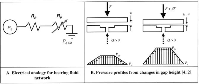
In order for the bearing to support a load and have stiffness, the flow must be restricted before it enters the bearing pad. This may be visualized with the electrical analogy shown in Figure 2.2A. In this analogy Ohm's Law of V = IR is replaced with P = QR. Here P is the pressure, Q is the volumetric flow rate, and R is the resistance to fluid flow. For this example RR is the restrictor resistance and has a fixed value. The fluid resistance caused by the fluid flow over the bearing lands, Rp, increases as a function of decreasing gap height cubed. Because Ps is fixed, as the bearing gap is decreased Rp increases, thus increasing the pressure drop over the lands and raising the pressure in the bearing pocket. This phenomenon can be seen in Figure 2.2B. As a load, W, is applied, the gap height decreases, creating a taller trapezoidal pressure profile, which results in a larger reaction force, giving the bearing stiffness.
Page 33
RR Rp
PA TM
A. Electrical analogy for bearing fluid network 4F SQ>O P"
*+
dF Q>O *LB. Pressure profiles from changes in gap height [4, 2]
Figure 2.2 Fluid relationships in hydrostatic bearings
2.1.2 Modeling bearing flow
Using lumped parameter modeling, most of the regions of hydrostatic bearings (with the exception of some types of restrictors) may be modeled as one dimensional, laminar, fully developed flow between two plates, as shown in Figure 2.3. The flow may be considered laminar as viscous effects dominate through the small bearing gap to create flow restriction, and the Reynold's number is << 2000. The flow may be considered locally fully developed because h << L [14].
-- u --- +
h -_
Figure 2.3 Velocity profile of fully developed flow
0
D O
u +u +v x Jy0a
+wjaUz
_ x2U a2 a+ 2 -UIy + WU + U + g 2 2x 0 (2.1)Equation (2.1) can be reduced using the following assumptions:
1. During operation under constant supply pressure, the flow is steady.
2. Since hydrostatic bearings use incompressible fluids, mass conservation though a uniform bearing gap requires that the velocity in the x direction be constant.
3. There can not be any flow through the walls of the bearing gap, so there is no flow in the y direction.
4. The flow is uniform and does not vary in the z direction.
5. Horizontal height changes are negligible, so body forces can be ignored.
The reduced Navier-Stokes equation is given by Equation (2.2).
(2.2)
Integrating Equation (2.2) twice and applying the non-slip boundary conditions of u(O)=u(h)=O, yields Equation (2.3) for the flow velocity.
u= ' -d-ty(h- y) (2.3)
2pu dx
Integrating the velocity over the entrance area of the bearing, which is defined by the height and width of the land, results in Equation (2.4) for the volumetric flow rate.
Q=wh (2.4)
12pu dx
Where w is the width of the land. To express pressure, flow rate, and flow resistance in the analogous form of V = IR, the pressure can be integrated over the land length L to
obtain Equation (2.5).
R = A - = 3(2.5)
Q h w
This expression is powerful because it can be used to express all the geometric parameters of the bearing as a fluid resistance. As such, the bearing may be modeled with lumped parameters, with each parameter being composed of variations of Equation (2.5).
2.2
Verification of flat plate assumption in journal bearings
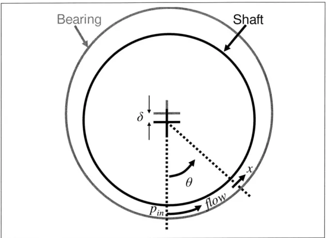
A problem arises when using the flat plate approximation for journal bearings: journal
bearings are not flat. Figure 2.4 shows a displaced shaft within a journal bearing. As a result of the curvature of the bearing, the gap does not decrease uniformly. Modeling
flow in a uniform gap is much simpler than in a varying gap, thus a flat plate approximation is advantageous if it doesn't deviate significantly from the curved plate model. This section will investigate the error associated with using the flat plate approximation instead of a curved plate model. The method used was adapted from [4,6]
Figure 2.4 Bearing eccentricity during shaft displacement
The gap height, h, is defined by the expression given in Equation (2.6).
h = hO[ - ecosI + ]
D )_
(2.6)
Where ho is the initial gap height before deflection, 0 is the initial angular position of the height being measured, x is the arch length position on the face of the bearing, D is the diameter of the bearing, and c is the eccentricity ratio defined by Equation (2.7).
(2.7)
By substituting Equation (2.6) into Equation (2.4), the pressure drop along the arch length is expressed by Equation (2.8). Page 37
Bearing
Shaft
i..
:U. : .dp 12pQ I
dx w ho3Ll cos(9±+II1(2.8)
D
x
the ratio = may be used to find the pressure drop along the arch length from L
Equation (2.8) using a definite integral. The resulting flow resistance in the circumferential direction is given by Equation (2.9).
R 12pL 2 1d
w= 3 f 3 d (2.9)
wh l-ecos O+-]
It is important to note that the ratio LID is different than the usual LID ratio that corresponds to the bearing length and diameter. In Equation (2.9) LID is the ratio of the land length and the diameter. Dividing Equation (2.9) by Equation (2.5) and evaluating at LID = 0.1, which is a realistic approximation [4], and an eccentricity of 0.5, which corresponds to the operating range of a typical bearing [2], the ratio of resistances at any radial position around the pad, 0 = 00 to 90', is very small (<1%). Thus, the flat plate approximation may be used to accurately model fluid film journal bearings.
2.3 Means of fluid restriction
As mentioned previously, restrictors are required in bearing fluid circuits. They induce a pressure drop in the fluid as it enters the bearing pad. When the resistance of the bearing lands increases, the pressure in the bearing pad increases. The bearing has stiffness because the load capacity increases with bearing displacement.
Table 2.1 Methods of bearing compensation
Compensator type Description
This type of compensator provides a fixed flowrate. Direct feed, constant Pressure in the pads is increased by restricting the flow flowrate over the bearing lands, so as the bearing is displaced the
pressure in the pads increases. The max pressure attainable is limited by the
power
of the motorpump.
This type of compensator uses viscous losses from laminar Capillary tubes flow. The restrictor is usually made from a capillary tube.
The length of the tube is adjusted to tune the restriction. Orifices cause a pressure drop by forcing the fluid around a sharp corner and choking the flow. This type of
compensation is more common in aerostatic bearings because of the low viscosity of the air. They are less
desirable for precision applications because they induce turbulent flow.
These restrictors are often made by splitting the flow into opposing bearing lands and forcing it over a compliant diaphragm. When there is a pressure difference between the roprtiona flands, the diaphragm will stretch to lower the flowrate to
the pocket with lower pressure. This lowers the opposing force against the bearing supporting more load, thus making
_the bearing
pair
stiffer.Surface self-compensated bearings
This method of restriction works by forcing the fluid through passages on the bearing surface. Each restrictor is
connected to an opposing pad. The main advantage of these compensators is that there are no small channels in which to
trnn nnrticlei cn olnoo-ino ie mnuh lie of q nrnh1pm Thiz
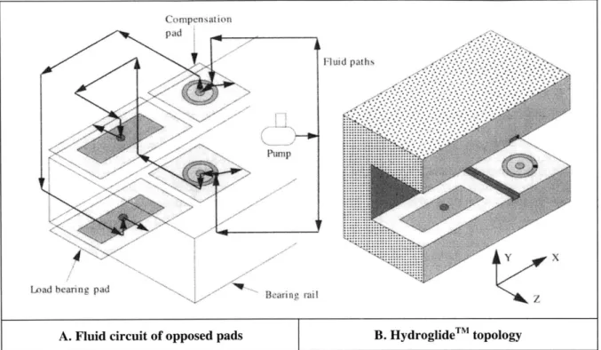
2.4 Surface self-compensated bearings
The following is a summary of surface self-compensated bearings from [1,3,15,16]. In these bearings the restrictors are located on the bearing surface. A pressure drop is induced by viscous losses in the flow through the bearing gap. Self-compensation provides the following advantages over other types of hydrostatic bearings.
1. Variable restrictors - Since restriction is accomplished on the bearing surface, the restrictor resistance changes with bearing displacement. If the restrictors are in an opposed configuration, shown in Figure 2.5A and Figure 2.6, greater pad pressures can be achieved. For example when the bearing is displaced down, the upper restrictor resistance (RUR) will decrease and the lower pad resistance (RLP)
will increase, raising the pressure and vertical force of the lower pad. If properly designed, these bearings can exhibit stiffnesses that are twice as high as fixed compensator bearings of the same pad size [1]
2. No tuning required - Self-compensated bearings automatically adjust the force between the pads and tend towards a stable neutral position. As a result no tuning is required to balance the pads.
3. Large fluid channels - The smallest features in the fluid circuit are on the bearing land. This makes self-compensated bearings much less susceptible to clogging than bearings that use small clearance restrictors, such as orifices and capillary tubes. The fluid flow over the restrictors and lands constantly cleans the bearing surface.
Fli paths
Pa
IYt Y77x
Load bearing pad
A. Fluid circuit of opposed pads B. HydroglideTM topology
Figure 2.5 HydroglideTM surface self-compensated bearing [1]
RUL
R
URR
y,rs
RLR
RLP
RLL P
Figure 2.6 Fluid circuit for surface self-compensated bearing
The HydroglideTM, shown in Figure 2.5, is a unique design in self-compensated bearings because the resistance of the restrictor is deterministic. Fluid flows from an outer annulus radially inwards to a center hole, shown in Figure 2.5A. This configuration is different
Page 41
Rearing rail
from early restrictor designs, where fluid flows outwards from a source to collection pockets [3,16]. The HydroglideTM is easier to model than other self-compensated
bearings because the bearing flow is in the opposite direction of leakage flow, making leakage not affect bearing performance.
CHAPTER
3
3DWN BEARING DESIGN
This chapter presents the process used to design the 3DWN HBP. The chapter begins with the inception and evolution of 3DWN technology then focuses on the design of the most recent 3DWN surface self-compensated HBP. The design process is composed of three stages: 1) satisfying the precision requirements of the HBP, 2) modifying existing bearing technology for incorporation into a wrapped structure, and 3) designing the remainder of the Template to include internal networks. Qualitative design choices based upon sound engineering knowledge compose the majority of this chapter. Quantitative methods behind design decisions are mentioned in this chapter with the full analysis explained in Chapter 4.
3.1 Inception of 3DWN technology
3DWN technology grew out of research on flat pneumatic and hydraulic actuators. The initial objective of that project was to research the feasibility of making flat, monolithic pneumatic and hydraulic actuators with pistons, actuator bodies, return spring mechanisms, and fluid routing channels. The actuators were designed to have fluid film bearings on the piston surfaces to reduce friction, as shown in (Figure 3.1 A). The bearing gaps were created by compliant end caps, which expanded when the piston was pressurized. A goal of the project was to enable the production of monolithic robot structures, shown in Figure 3.1 B, which could be low-cost, expendable, and used for educational or military applications.
Figure 3.1 Flat actuator concept and implementation
Engineering flat actuators presented many challenges. Sealing the piston was near impossible as it had sharp corners and the compliant end caps bowed under pressure. The end caps bowing instead of deflecting uniformly creates a parabolic bearing gap. The restriction of the bearing gap scales with the gap height cubed, so small errors in gap height are detrimental.
To overcome sealing issues the author conceived of a conventional cylindrical piston which slides on aerostatic journal bearings. The internal channels and features of the bearings would be made of cylindrical layers, similar to the flat layers of the flat actuators.
After some consideration the author realized that the cylindrical layers could be made from one sheet wrapped around the piston. Each layer could contain 2D cutout features which would align to form 3D channels when the sheet was wrapped. The first model of 3DWN technology, shown in Figure 3.2, was made from paper.
Compliant Return Spring Actuator Body Flexure Seal AiFlxuer Berina
El,
B. FlatBot concept A. Flat actuator prototype with integrated air bearing3.2 Early 3DWN bearing prototypes
The 3DWN aerostatic bearings shown in Table 3.1 were constructed as the first proof-of-concept prototypes. Each of these prototypes was made from plastic shim stock that was adhered with double-stick tape. The first bearing prototypes were aerostatic instead of hydrostatic. A compressed air instead system was more convenient for bench-level testing, as air can be directly regulated from storage tanks. The information that was learned through these prototypes as well as the difficulties associated with each prototype, is presented in Table 3.1.
Table 3.1 Progression of early 3DWN prototypes
Prototype What was learned
Origin of a. Flat actuators not working - deformation = leaks
1 idea b. Round actuators with incorporated wrapped bearing
c. Wrapped structure for internal channels a. Wrapped Template features align First air b. Internal networks carry fluid prototype c. Compliant Body
d. Feeding channels warp bearing surface n r a. Casting into housing improves body stiffness
3 bearing b. Plastic too compliant
c. Adhesive tape has low peel strength too low
I
prototype d. Difficulty cutting orifice with laser3.3 Motivation to design a HBP
The following reasons drove the decision to switch to a hydrostatic rather than aerostatic bearing design for the proof of concept prototype:
* Incompressibility: instabilities, such as pneumatic hammer, can occur in aerostatic bearings [1, 17, 18]. Hydrostatic bearings use incompressible fluids, and thus are not generally susceptible to instabilities caused by compressibility.
" Viscosity: Commonly available oils can be on the order of 104 times [19] more viscous than air. For this reason the bearing gap can be large while still providing acceptable fluid resistance. Larger bearing gaps make the bearing's performance less susceptible to bore surface irregularities that result from manufacturing errors. High viscosity makes the bearing less susceptible to the fluctuations in performance that are caused by turbulence . The increased sensitivity is due to the decreased Reynolds number of the flow.
* Surface compensation: Unlike aerostatic bearings, hydrostatic bearings use viscous losses in the fluid as a means of restriction. The fluid can be restricted on the bearing surface instead of through a small cross sectional area, e.g. an orifice or capillary tube, which reduces the chances of clogging.
* Self-compensation: Self compensated bearings have higher load capacity and stiffness than fixed restrictor bearings, as was mentioned in Chapter 1. Self-compensated bearings require cross channeling between the pads and restrictors; the formation of internal networks is an ideal demonstration of 3DWN technology.
3.4 Satisfying precision requirements of the HBP
The bearing bore has to meet a certain level of precision in order to perform properly, avoid contact with the shaft, and have a uniform fluid film. The proposed 3DWN technology includes the use of off-the-shelf precision parts to meet the precision requirements of the bearing. This section defines metrics for the off-the-shelf components. The precision requirements for hydrostatic bearings are:
* Surface finish: The maximum peak-to-valley surface roughness of the hydrostatic bearing components should not be greater than one-fourth of the bearing gap [1, 4].
* Bore diameter and roundness: The bore should not have errors great enough to disturb the fluid flow or cause mechanical contact with the shaft. The diameter, circularity, and surface finish errors should also not be greater than one fourth the bearing gap.
3.4.1 Characterization of surfaces
The following information on surface finish is a summary from Applied Tribology, Surfaces and their Measurement [20]. There are three important factors in defining the roughness of a surface: 1) the roughness, which is a metric of the size of short-wavelength irregularities, e.g. asperities, 2) the waviness, which is a metric of the long-wavelength form error, and 3) the lay, which is the direction of the primary surface irregularities. An example surface with these factors is displayed in Figure 3.3.
Lay
Total surface profile
Waviness profile
Figure 3.3 Example surface roughness profile [20]
The average roughness, Ra, is the most common metric used to describe surface roughness. This is defined, as shown in Figure 3.4, as the average deviation of individual high and low points on the surface from the arithmetic mean height of the profile. In order to incorporate the effect of waviness in Ra, the points are usually sampled over five times the longest wavelength.
K
A
Ra / * / / I -' -, I ~Ij ,' ~/ I j I, I - I I, j IRIS I I, ~ ITFigure 3.4 Determination of Ra value [21]
3.4.2 Satisfying surface finish requirements
One hypothesis associated with 3DWN technology is that the surface finish constraint of the bearing is satisfied by the surface finish of the Template. It is generally good design practice to specify that the max peak valley roughness, Ry, of the bearing bore should not be greater than one fourth of the bearing gap height. Typically Ry is three times Ra [20]. If we accept this relationship, the metric for the required Template surface finish is defined by Equation (3.1).
3.4.3 Satisfying bore diameter and roundness requirements
Using replication to form the bearing bore is another hypothesis included in 3DWN technology. As described in Chapter 1, the Template is wrapped around a mandrel to inherit its precision diameter and roundness. Errors in the mandrel diameter may be transferred to the 3DWN HBP. Equation (3.2) is used as a metric to ensure that the bearing bore and mandrel surface asperities remain less than one fourth the gap height. In Equation (3.2), eR is the radius error, cc is circularity error, and Ra is the surface finish.
ER C +3Ra Lh (3.2)
4
3.5
Design of 3DWN HBP bore surface features
The following functional requirements were outlined for the HBP bore surface features. The successive subsections describe the design parameters used to satisfy the following functional requirements.
1. Surface-self compensation: Compensation can be accomplished through restrictors on the bearing surface instead of small-area restrictors that are susceptible to clogging. Self-compensation requires cross-channeling between pads and opposing restrictors, an ideal application to showcase 3DWN technology.
2. Accommodation of overlap region on bore: There is an overlap region of the Template on the bearing. The overlap has to be incorporated into the bearing surface features without negatively affecting performance.
3. All features cut as 2D profiles: Conventional bearing features cannot be directly applied to 3DWN bearings because all Template features have to be 2D through-cuts.
4. Even number of pads: The bearing has to have an even number of pads as to so each pad is directly opposed by another pad [6,16]. Odd pad arrangements can lead to an imbalance of radial forces, which can move the shaft off center.
3.5.1 Inspiration for HBP surface feature design
The 3DWN HBP surface feature design was inspired by the self-compensated journal bearing design shown in Figure 3.5 [22]. The bearing self-compensates through annular restrictors that connect to opposed pads. The bearing in Figure 3.5 was used as a starting point since its design is deterministic and therefore more easily realized. Modeling of the
3DWN HBP is included in Chapter 3. 7IA 718 71C- A C A/ 6 4 A i -1A -62AA 0..~ ~ 68A~.GS 65A 62AA 66Aes 0- 69C 6 4A '7 // 60- -70D 69D OA-69 so-0 - -- 7J _2&A I ifA _7C 638 / 6B 67p I -i3A 3B6 61A---- - - -16 A_ 66A I / 6 S.718 )7 I 69B ~ ~~4~6_ _ 169 /7 / 70A 610 2 7 4 70C
A. Restrictor-pad cross-connection networks B. Self-compensated pad bore surface features Figure 3.5 Hydrostatic self-compensated journal bearing [22]
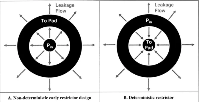
The flow through the restrictor is responsible for the deterministic nature of the design shown in Figure 3.5. Early surface self-compensated bearing designs relied upon bearing flow that occurred in the same direction as the leakage flow. This is demonstrated in Figure 3.6 A. The restrictor in Figure 3.6 A is not deterministic because leakage flow
I
Leakage Flow
affects the amount of flow to the pad. The models that capture the flow in Figure 3.6 B are deterministic because the annulus is pressurized and the leakage flow is separated from the flow to the pad.
Leakage Flow
t
-~ II
I
B. Deterministic restrictorA. Non-deterministic early restrictor design
Figure 3.6 Annular restrictor designs for hydrostaic surface self-compensated bearings
3.5.2
HBP pad configuration
As mentioned in the beginning of this section, hydrostatic bearings require an even number of pads that are equally circumferentially spaced around the bore. The pads need to be in opposed pairs so as to balance the resultant forces, as shown in Figure 3.7 A. If the pads are not opposed, as shown in Figure 3.7 B, uneven radial forces will cause the shaft to move off center.
Page 51
Bearing Pad
Force
A. Even pad configuration
Bearing Pad
4-
Force
B. Odd pad configuration Figure 3.7 Comparison of pad configurations
The chosen layout of bearing surface features for the 3DWN HBP is shown in Figure 3.8. A configuration of 2 axial sets of 4 pads was chosen since it simplifies the bearing design by using the minimum number of pads that are required to fully constrain the shaft (4 degrees of freedom). The pads, not the restrictors, are located at the ends of the bearing to
L
further improve moment stiffness. The ratio of L = 2 was chosen for compliance with
D
suggested shaft constraint configuration and St. Venant's principle [1]. I
L
Pad
Land
Restrictor
Drain
Groove
Pad
Figure 3.8 Chosen 3DWN HBP bore surface features layout
3.5.3
Overlap region of bearing bore
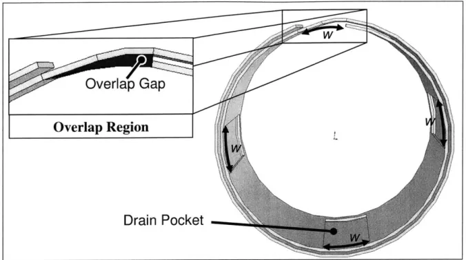
There is an overlap on the bearing bore, shown in Figure 3.9. As a result of the 3DWN HBP is made from a wrapped sheet. At first glance the overlap region may look like a glaring violation of required bore precision. In reality the overlap region can be used to the advantage of the designer.
Overlap Gap
Overlap Region
Drain Pocket
Figure 3.9 Geometric matching of overlap region
The overlap region creates an overlap gap on the bearing bore, as shown in Figure 3.9. These gaps can be used to drain fluid from the pads. Fluid drains are desirable features in hydrostatic bearings BECAUSE they prohibit flow interaction between the pads, making the pad flow analysis deterministic. Geometrically opposed drain pockets can be cut into the surface features if the arch length and position of the gap can be determined. The pockets are geometrically opposed to balance the forces from the pads. The analytical model describing the overlap region is included in Chapter 3.
The overlap region raises another issue of concern: the amount of Template required to jump from one layer to the next is greater than the arch length of the overlap. As a result, extra material needs to be added to each wrapped layer. A model for the extra material required is included in Chapter 3. This model is expanded to map all 3D bearing and internal features to features in the Template.


![Figure 3.4 Determination of Ra value [21]](https://thumb-eu.123doks.com/thumbv2/123doknet/14687131.560462/48.918.121.792.294.664/figure-determination-ra-value.webp)