Publisher’s version / Version de l'éditeur:
Vous avez des questions? Nous pouvons vous aider. Pour communiquer directement avec un auteur, consultez la première page de la revue dans laquelle son article a été publié afin de trouver ses coordonnées. Si vous n’arrivez pas à les repérer, communiquez avec nous à PublicationsArchive-ArchivesPublications@nrc-cnrc.gc.ca.
Questions? Contact the NRC Publications Archive team at
PublicationsArchive-ArchivesPublications@nrc-cnrc.gc.ca. If you wish to email the authors directly, please see the first page of the publication for their contact information.
https://publications-cnrc.canada.ca/fra/droits
L’accès à ce site Web et l’utilisation de son contenu sont assujettis aux conditions présentées dans le site LISEZ CES CONDITIONS ATTENTIVEMENT AVANT D’UTILISER CE SITE WEB.
Building Research Note, 1982-09
READ THESE TERMS AND CONDITIONS CAREFULLY BEFORE USING THIS WEBSITE. https://nrc-publications.canada.ca/eng/copyright
NRC Publications Archive Record / Notice des Archives des publications du CNRC :
https://nrc-publications.canada.ca/eng/view/object/?id=517e8f5f-4744-4262-96d9-87aa3039e33e https://publications-cnrc.canada.ca/fra/voir/objet/?id=517e8f5f-4744-4262-96d9-87aa3039e33e
NRC Publications Archive
Archives des publications du CNRC
This publication could be one of several versions: author’s original, accepted manuscript or the publisher’s version. / La version de cette publication peut être l’une des suivantes : la version prépublication de l’auteur, la version acceptée du manuscrit ou la version de l’éditeur.
For the publisher’s version, please access the DOI link below./ Pour consulter la version de l’éditeur, utilisez le lien DOI ci-dessous.
https://doi.org/10.4224/40000520
Access and use of this website and the material on it are subject to the Terms and Conditions set forth at
A simple method for determining the heating requirements of
direct-gain passive solar houses
Ser
TZl
A SIMPLE METHOD FOR DETERMINING
THE
€ E A T I N G REQUIREI4ENTSOF
DIREfl-GAIN PASSIVE SOLAR
HOUSESS.A.
Barakat andD,M.
SanderA simple method to calculate the heating energy requirements
of direct-gain passive solar houses is presented. The calculation
procedure is baeed on the concept of solar utilization factor,
which i s d e f i n e d a s that fraction of the t o t a l solar gain through
all windows of a house that contributes to the reduction of
heating requtrements, The method is incorporated into a graphical procedure that can be easily used during the design process to
f i n d the combinatloa af south w i n d w area and t h e m 1 storage maea
that d n l m i z e s purchased space heatkng energy.
It
is applicable to t h e co lete range o f housing types, f r o m high-maas direct-gain"S
houses to ovlnass sun-tempered ones.
LNTRODUCT ION
The need
for
a simple method to estimate the heating energy requirementof a hwee is widely recognized. Such an estimating technique could be used
for comparing alternatfves i n the design proceas and for evaluating house designs t o determine their canpliance with energy standards.
An important aspect of such a method is the a b i l i t y to estimate the amount of solar energy collected through the windows of a house and u t i l i z e d t o o f f a e t heat losses.
A number of methods have been developed to eetimate the net salar contrtbution t o apace heating f o r dlrect-gain passive salar de81gns.
The ~olar-load-ratio method, (SLR), developed by the LOB ATamos Scientific Laboratorylr2 is widely used
In
the United States and Canada. Althoughthe SLR method is easy t o use, the range of parametere that can be
considered ia l i m i t e d to those used tn the reference d e s i g n s .
In
particular,it cannot be used t o examine the effects,
em
a s p e c i f i c design, of factorssuch as the number of glaziaga and the amount of t h e m 1 storage. The
SLR
method
hae,
however, been incorporated intomaw
other graphical a d simplecomputerized t echniquea.
Another approach t o estimating the solar contrfbution is the
method relfes on solar radiation s t a t i s t i c s to detemlne the fraction of s o l a r gain that is not useful and t h a t must be e l f d n a t e d to prevent overheating. Hore parameters can be considered than with the SLR method, but more calculations and greater involvement with radiation data are
required.
It
is, therefore, not as widely used as the SLR method.Recently, hawever, the "un-utilizability" s y s t e m was made easier t o apply
through the use of tables and graphs4.
'She procedure presented in this paper combines the s i m p l i c i t y of the
SLR
method with the f l e r d b i l i t y of t h e "un-utilizability" method.It
permits calculation of the heating energy requirements of conventional agw e l l as direct-gain passive solar houses, and is applicable t o the complete
range of housing types, from the high-mass direct-gain to the l o w s s
sun-tempered.
The
calculation can be performed on a seasonal, rather than a monthly,basis. T b l s makes it e a s l e r to uee, and a h a p e r m i t s it: to be incorporated
into a graphicdl technique whtch cam be a p p l i e d to determine the optimum* combination of s o u t k f a c i n g window area and thermal storage mass. The
graphical technique can a180 be uaed to i l l u s t r a t e t h e sensitivity of
seasonal heating energy requirements to change8 i n glaas area, type of
glazing, or thermal mass. Examples for a Canadian location ( O t t a w a ) indicate that thfs s e n s f t i v i t y i s less than might be commonly expected.
The energy con8umption values measured in the NRC passive t e s t units
d u r i q the 1981-82 heatfng season have been compared arb the corresponding
values calculated using this method5. The calculated values w e r e in close
agreement w i t h the measured results, the maldrrmm difference amounting t o
less than 5%.
TEE UTILIZATION FACTOR
The calculatioe procedure is baaed on the concept of the solar
u t i l i z a t i o n factor. T h i s factor, qs Is defined as that fraction of the
t o t a l solar gain, through all w%ndows of a hwse, that contributes t o the
reduction of the heating requirement; that is,
= Useful salar gain
9s %local solar galn
The useful solar gain far any hour includes the solar gain used to o f f s e t h e a t losses during that hour, plus the portion etored In the t h e m 1 mass
and used to offset losses a t a l a t e r time. It does not include the excese gain t h a t m a t be discarded to prevent roam temperature from exceeding a
preset maximum, nor any gain u t i l i z e d t o offset additional losses caused by
a rise in room temperature above the thermostat setting.
The seasonal heating energy requlsement (H)
for
a house is given bywhere:
L
= n e t heating load,q, = utilization factor for solar gains,
6, = total ~ o l a r heat galas through windows.
The
solar
u t i l i z a t i o n factor is expressed as a funcrios of two normalized parameters, the " ' g a i ~ l o a d ratio"'(GLR)
and the "thermalmass-gain ratio"
(MGR).
The galn-load ratio is the ratio of solar gain through d n d w s , Gs,
to the net heating load, L, or:
This gain-load r a t i o d i f f e r s from the solar load ratlo (SLR), as
d e f i n e d in Reference 2,
In
that the GLR Includes heat losses through windcrws while the SLR does not. Moreover, the GLR includes solar gains through allthe windcrws, n o t only those f a d n g s mth.
The mass-gain r a t i o reflects the thermal storage characteristics of
the b u i l d i n g as well as the area, type and osientatfon of the glazfng.
It is defined as,
where: C = thermal capacity of the building interior
CMJIK),
gs = average hourly solar gain f a r season (MJ/hs),
( g s = Gs/houra in heating season).
The thermal capackty, C,
is
calculated 8s the "effective massw of theb u t l d i n g multiplied by its specific heat. The effective mass is the mass
actually available to store heat as a result of direct solar gains, or that
in close contact with ram af r so that any change
in
roomair
temperatureaffects the mass temperature,
This
normally includes the mass inside theinsulating layer of the walls and ceilings, but excludes the exposed
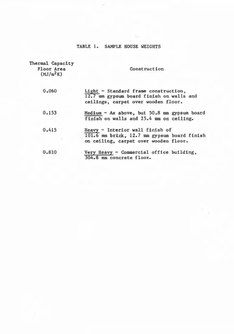
concrete of uninsulated basement walls and floors. Typical, thermal capacity
values for
four
types of constructionare
g l v e a kn Table 1.Solar u t i l i z a t i o n factor^ were derived using hour-by-haw computer simulation
of
a large number of houses having different: combinations ofspace heating load, thermal storage mass, solar gain and allowable
temperature awing for f i v e Canadian location&
.
The . r e s u l t i n g utilizationfactore w e r e correlated using the parameters GZR and MGR, and w e r e
independent of geographical laslation as a h m in Figure
1.
The figure shmsthe solar utflizatioa factor platted against the GZ,R
for
various values ofMGR and a room temperature rise of 5 . 5 " C . Curves for the cases of O* and
2.75"C temperature rises are a l s o available in Reference 5.
C A L G W T I O H OF
HEATING
REQUIREMENTThe basis of the c a l c u l a t i o n method is the simple heat balance equation
of the house, as &pea by Equation (1).
The seasonal net heating h a d , L, is calculated as:
where: La, = total heat losses due to transmission through exterior walls,
windows, c e i l i n g s , etc.
,
t, = t o t a l heat losses due to indoor-outdoor aSr exchange (in£ i l t r a t i o n
+
ventilation),Lb = total belou-grade heat loss,
ni
utilitatian factor for internal gains,Gi = total heat galas f rorn internal sources ( l i g h t s , equipment, people, e t c * ),
The seasonal t o t a l of heat losses due to transmissbon through the exterior
w a l l s , wiudcws and c e i l i n g is calculated ae:
where: M = number of hours in the heating season,
-
B1 = average indoor a i r temperature ( O C ) ,
go
= average outdoor a i r temperature ('C),UA
= thermal conductance of each component including a l lwindms
(WIK).
The conductance values, UA, can be calculated as described tn the AS-
andb book^,
while8,
is available for many locattans from weather dataThe heat losses due t o indoor-outdoor air exchange,
La,
can becalculated from the equation:
where:
Am
a air change sate of house (air changes per hour)v
volume of house (m31.
The total below-grade losses can
be
calculated using the procedurerecently developed by Mftalas8
.
The mgnktude of the fntcrnal gains, G depends on the occupancy of the house. While date concerning the rate $'heat release by various
appliances are available, tt is always necessary to make arbitrary
assumptions regarding occupant behaviour and, therefore, of the internal
gains. For m o s t s i t u a t i a n ~ in which GI is less than 25X of the heat losses,
all of the internal gaim are assumed to be u s e f u l
(rr
= 1).The seasonal t o t a l solar gain through the windows is calculated as
where the subscript 1 represents the orientatLon of window and:
4% = glass area,
SCI = shading coefficient: of window,
Q i = t o t a l solar gain through unit area of a single sheet of standard glass, given by Of = 0.83 B i ,
where Hi is the total seaeonal solar radiation incident on the window
E U ~ f B C ~
Values of the total monthly solar radiation incident on surfaces of
different orf entations and t iltg are tabulated for a number of locations.
In
Canada t h i s information is available from the Atmospheric EnvironmentService as 10-yeas averages for 130 locations. The
seasonal
solar gain canbe obtained by summing the values f o r the appropriate months.
Equatiom
(2)
and (3) are used to calculate t h e GLR andM X .
The utilization factor, T J ~ , 1s thenfound
from F i g u r e1
and the spaceSAMPLE CALCULATION
The method w i l l be i l l u s t r a t e d by calculations for a two-story h w s t
located in Ot taws, Canada. The assmed heatlng season runs from October to
April incluskve (5064 hours). Far t h i s period the average outdoor
temperature is -3.25OC and the gofar cner incident on south- and
north-faefng surfaces is 2910 and 510 XI/
,
rcsptctivelym The averageindoor temperature 18 assmed to be
21°C.
S
The house is w e l l insulated (B6 walls,
R10
ceili~lg and R2.1 basementw a l l s ) and of frame c o n ~ t r u c t i a n . It has
7
of
aortkfacing and14
m2 ofsouth-facing double glazed windows. The characteristics of the house are as
follcws: floor area u house v o h e = IJA (walls) =
UA
( c t f l i n g ) = UA (north d n d o w s ) = U A(south
ain4ms) = shading coefficient = averagein£
i l t r a t l o n = 207 n? 860d
50 WJK 1sw/a
23.2
W/K 46.5WIK
6
-880.25 a t r changes per hour.
A, Ealculatioa of Lt, from Equation ( 5 ) ,
Lt
-
57 400 MTB. Calcvlatioa of la, fro. Equation ( 6 ) .
L = 31
loo
w
a
C
.
Calculation of5 ,
from Reference8,
D, Internal gains art assumed t o
be
G-
15 000K
l
i
E. Calculation of
L,
fromEquation (41,G. Gain-load ratio, from Equation (21, GLR = 3 2 4Q0 = 0.36
90 5130
H. Mass-gasn ratio from Equatlw ( 3 ) and aaswning thermal capacity of
0.06 W/K p e r U? of floor area (Table
11,
1. From F i g u r e 1,
ns =
0.88
J.
Substituting into Equation (1) the seasonal heating requirementGRAPHICAL DESIGN METHOD
Solar utilization may a l s o be presented as the f r a c t i o n of the net
heating load
which
~mst: be s u p p l i e d by the heatfag system. This fraction,(Fh), wlll be referred t o as the "purchaaad heating fraction"\ (It is, in
f a c t , equal to one minus the solar heating fraction.)
Figure
2
s h m Fh p l o t t e d as a function of the parameters GLR and MGR.These curves a p p l y for a maximum allmable temperature swfag of 5.5-C;
graphs for other temperature s d n g s are given in Reference 5.
The heating energy requirement far the house can then be obtained from:
The above procedure can be incorporated into a simple graphical methad
to examine the effect of south-facing windm type and area, as well aa
thermal storage, on the heating requirement of a house.
Figure 2 can be reformatted aa shown in Figure 3. On the same sheet
t h e follming can be p l o t t e d againat south windm area for a particular house design:
A . Solar gain,
G,,
calculated as a linear function of southwindow area, a s s d n g that the areas of windows on the ather
orientatf ons remain f i x e d :
where
Go
~ E I thesolar
gain through a l l orientations other thansouth.
B. N e t house load, L, calculated as a linear function of south window
a r ea:
where
L'
is the transmission loss of the house v i t h no tsouth-facing rindov (Asouth =
0)
and all south windms replaced by w a l l .C. GLR, obtained by dividing G g by L at a number of p o i n t s .
D. MGR, obtained by computing C N/GB for a number of values of %mth
-
The procedure t o construct the relationship between window area and
purchased heating requirement %s as follms (Figure 3 ) :
I . For any south window area, draw a vertical l i n e to intersect the
solar gain line, the net load l i n e , the
GLR
curve, and the W Rcurve at pointa A, B,
C
andD,
respectfvcly.2. Ilrm a horizontal l f n e from point: C to intersect: the purchased
heating fraction plot for t h e appropriate MGR (measured at D) at point E {same interpolation between MGR curves may be necessary).
This determines the purcha~ed heating fraction, Fh
.
The heatfngrequiremnt, R, is then equal t o t h e product of Q, and L. T h i s
is obtained graphically in the next three steps.
3. Draw a horizontal l i n e from point B
to
fntessect the vertical lineof Fh = 1.0 at
X,
Cannect a l i n e between pointX
and p o i n tY
( p o i n t of interaectfon of the vertical l i n e thraugh Fh
-
0 and the zero energy l i n e ) .4 . Draw a vertical l i n e from point E to meet t h e l i n e XY at F.
5, Drew a horizontal l i n e from point F t o meet t h e o r i g i n a l vertical
line of S t e p 1 at p o i n t G. The energy value a t p o i n t G represents t h e purchased heating energy assaciated with t h i s south wfndow
area.
6, Repeat: steps 1 through
5
for other south window areas and draw a curve through all G p o i n t s . This curve represents the relationship between AsOuth and purchased heating energy.A change in thermal storage for the same house can be accommodated simply by calculating new values of MCX
and
repeating the above. A changein window type requires repetition a f the entire procedure b e g h n i n g by
recalculation of both G, and L.
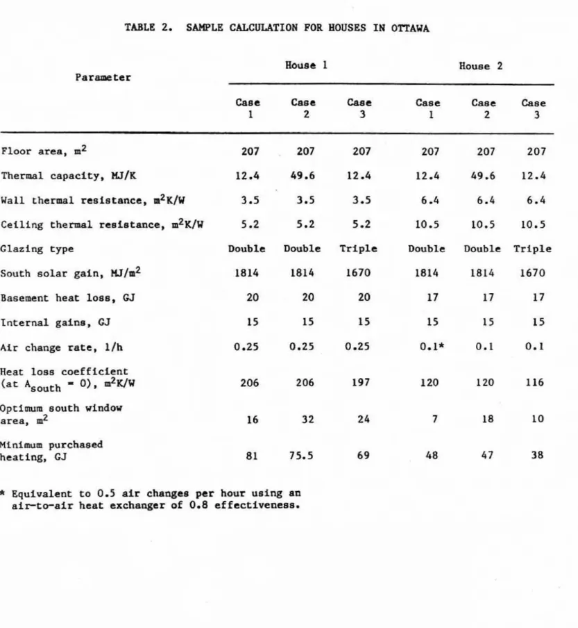
Examples are presented in Ffgures 4 and
5
for t w o different houseenvelope constructions {thermal resistance] in Ottawa, Canada. For each example, three optfons were evaluated:
1. light frame constructien with all vindows d o u b l e g l a z e d ,
2, same as
L
but wfth four times the amount of thermal storage,3, l i g h t construction with all windows t r i p l e g l a z e d .
Details of the six cases examined are given in Table 2 alang d t h the
minimum purchased heating required far each case and t h e optimum south window area.
S€?MMAKY AND OBSERVATIONS
T h i s s i m p l e graphical procedure may
be
used to determine, far any hauseconstruction, the optimum combination o f 6011th window area, windm type and
thermal storage mass. The method w i l l subsequently be used to develop
guidelines f o r t h e desfgn of df rect-gain passive solar houses in Canada. The fallowing observations regarding direct-gain passive solar houses in the Canadian clfmate were arrlved at by application of t h i s method t o a
number of house designs for the Ottawa climate.
The
curves of purchased heating versus south-facing window area arevery shallow around the optimum area.
In
general, a 50% change in s o u t h window area on either afde of the aptfmum value would result in a s m a l lchange i n purchased energy requirement (a maximmi a £ 4% in the s i x cases
The oprimum south windm area decreases for the mare energy conserving houses. For d o u b l e g l a z e d w i n d m s and light-weight construction, the
o p t i m a area is about 8X of flaor area for aa 80 GJ house (House 1). This
reduces to 3.5% of f l o a r area for the more cnerjy conscrvlng 48 GJ house
(House 2).
While en increase in
the
thermal storage allows use of m o r e windaws andresults i n a reduction in purchased energy, a larger reduction in purchased energy c m be achieved with a smaller area of triple-glazed windows. Taking
the optimr d a u b l r g l s z i n g cascs as the b a s i s for comparison, a fourfold
increase in the mass results in a 7% reduction in purchased heating for
Rouse 1 and 24: f o r Rouse 2. The use of triplwglazing results
In
reductionsof 15% and 21I f o r Houees 1 and 2 , rtspectivcly.
REFERENCES
1. Wray, W.O. Design
and
Analysis of Direct Gatn Solar Heated BaLldings,tA-8885+S, Los M m o s Scientific Laboratory, 1981.
2. Balcomb, J.D., et al. Passive Solar Design Randbook, Vol. 2, Passive
Solar Design Analysis, USDOE/CS-O~ 27/2, 1980.
3. Honeen, W.A,, S.A. Klein and W-A. Beckman. Ptedfcting of Direct Gain
Solar Heating System Performance, Solar Energy, Vol. 27, No. 2,
pp. 143-147, 1981.
4. Klein, S.A., e t al. Tabular Data for the Un-Utilizabifity Passive Solar Design Method, Proc. 6th National Passive Solar Conference, Portland,
pp. 328-332, 1981.
5 . Barakat,
S.A.
and D.M. Sander, Utilization of Solar Gain throughWindms for Heating Houses",
BRN
184,
Dlviskon of Building Research,Natlonal Research Council of Canada, Ottawa,
1982.
6 . ASHElAE Handbook af Fundamentals. Amtrican S o d e t y of Fiesting,
R e f rigeration and Air Conditioning Engineers, New 'Pork, Chapter 22,
1981
7. Canadian EFosmals-Temperature. Atmosphtric Environment Service, Dawnsvicw, Ontario, 1975.
8. MitaEas, G.P. Basement Reat Loss Studies at
DBRIW,
Division ofBuilding Rtseazch, Natkonal Research Council of Canada, (DBR Paper
T h c m l Capacity
Floor Area
WJ/rn2~)
TABLE 1. SAMPLE HOUSE WEIGHTS
Construction
L i ht
-
Standard frame construction,&-
m g y p e m board f i n i s h an w a l l s andc e i l f n g s , carpet over wooden f l o o r .
Medium
-
As
above, but 50 -8 mm gypsum board finish on w a l l g and 2 5 . 4 mn on ceiling.0.415 Heavy
-
I n t e r i o r wall f i n i s h of101.6 m b r i c k , 12.7 mm gypsum board f i n i s h
on c e i l i n g , carpet over wooden f l o o r .
Very Heavy
-
Commercial o f f i c e b u i l d i n g ,TABLE 2.
SANPLE CALCUUTXON FOR HOUSES IH OTTAWAHouse 2
Case Case Caac Case Case Case
1 2 3 1 2 3
Floor area, m2 207 207 207 207 207 207
Thermal capacity, W / K 12
.4
49.6 12 -4 12.4 49.6 1 2 . 4 Wall thermal resfstance,m2Ww
3.5 3.5 3 .SCeflf ng thermal rcslstance, m 2 ~ / W 5 . 2 5.2 5 -2
Glazing type Double Double T r i p l e
South s o l a r gain,
w/m2
1814 1814 1670Basement heat los~,
GJ
20 20 20Internal gains, GJ 15 15 15
A i r change rare, 1/h 0.25 0.25 0 -25 Heat loss coefficient
(at *Borrth
-
Q), &I[Iw O p t i m u m south window area, m2M t n f m u m purchased
heating, GJ
*
Equivalent t o 0.5 a i r changes per hour using an a i r t o - a i r heat exchanger of 0.8 effectfreneas.F I G U R E I
SEASOHAL SOLAR U T l l l Z A f l O N FACTOR !ROOM rEMPERAKURE S W I N G
-
5 . S W C 1a 0.3 0.6 0 . 9 1.2 1.5
GLR
SE4SDHAl PURCHASEO H E A T I N G FRACTION l R O O M rEMPERkTURE S W l H G . 5.5"CI
r
N A M E
-
Dl3 R PROJECT E X A M P L EF I G U R E 3
N AMZ D B R
PROJECT
O T T A W A , C A N A D A
F I G U R E 4