HAL Id: cea-03149385
https://hal-cea.archives-ouvertes.fr/cea-03149385
Submitted on 23 Feb 2021
HAL is a multi-disciplinary open access archive for the deposit and dissemination of sci-entific research documents, whether they are pub-lished or not. The documents may come from teaching and research institutions in France or abroad, or from public or private research centers.
L’archive ouverte pluridisciplinaire HAL, est destinée au dépôt et à la diffusion de documents scientifiques de niveau recherche, publiés ou non, émanant des établissements d’enseignement et de recherche français ou étrangers, des laboratoires publics ou privés.
Fluoride ion batteries – past, present, and future
Mohammad Ali Nowroozi, Irshad Mohammad, Palanivel Molaiyan, Kerstin
Wissel, Anji Reddy Munnangi, Oliver Clemens
To cite this version:
Mohammad Ali Nowroozi, Irshad Mohammad, Palanivel Molaiyan, Kerstin Wissel, Anji Reddy Munnangi, et al.. Fluoride ion batteries – past, present, and future. Journal of Materials Chemistry A, Royal Society of Chemistry, inPress, 9, pp.5980-6012. �10.1039/D0TA11656D�. �cea-03149385�
Page 1 of 52
Fluoride Ion Batteries – Past, Present, and Future
Mohammad Ali Nowroozi
a,§,Mohammad Irshad
b,§,Palanivel Molaiyan
c,§,Kerstin Wissel
a,§,
Anji Reddy Munnangi
d,*and Oliver Clemens
a,*a Universität Stuttgart, Institut für Materialwissenschaft, Chemische Materialsynthese,
Heisenbergstraße 3, 70569 Stuttgart, Germany
b Université Paris-Saclay, CEA, CNRS, NIMBE, LEEL, 91191, Gif-sur-Yvette, France
c Institute of Particle Technology, Technical University of Braunschweig, Volkmaroder Str. 5
38104 Braunschweig, Germany.
d College of Engineering, Swansea University, Fabian Way, Swansea SA1 8EN, United Kingdom § These authors contributed equally
Page 2 of 52 Abstract
Fluoride-Ion Batteries (FIBs) have been recently proposed as a post-lithium-ion battery system. This review article presents recent progress of the synthesis and application aspects of the cathode, electrolytes, and anode materials for fluoride-ion batteries. In this respect, improvements in solid-state electrolytes for FIBs as well as liquid electrolytes will be discussed. Furthermore, the achievements regarding the development of cathode and anode materials will be considered. With the improvements made, the field is currently attracting a steady increase of interest, and we will discuss the potentials of this technology together with necessary future milestones to be achieved in order to develop FIBs for future energy storage.
Keywords: fluoride ion batteries, liquid electrolytes, solid-state electrolytes, ionic conductivity, intercalation-based cathode materials, conversion-based cathode materials, intercalation-based anode materials, conversion-based anode materials
Page 3 of 52
1
Introduction
Modern life is highly dependent on energy storage devices. From portable electronics to electric vehicles (EVs), electric trains and airplanes, which may or may not become the future of mobility, all benefit from modern rechargeable energy storage technologies. Moreover, energy storage devices are required to store the energy generated from solar, wind, and tidal sources. Therefore, the demand for efficient and sustainable systems is increasing drastically.
Lithium-ion batteries (LIBs) turned out to be the best choice for portable electronics and are the main contenders for emerging EVs due to their high energy density, specific power, and cycling stability.1 However, the large adoption of LIBs for these applications led to the depletion of lithium
resources, which are low in abundance and geometrically constrained. Not only the abundance of lithium, but also the abundance of other key elements (e. g., Co) used in LIBs is critical. Even if Cobalt-free and high energy nickel-rich materials have been developed recently, the safety and thermal stability of such Ni-rich materials is a concern. Though this might not necessarily impact small scale technologies, these aspects will become of tremendous importance for large scale storage. In this context, it is important to consider alternative energy storage systems, which work based on shuttling ions other than Li+.
In response, several alternative battery technologies were proposed and investigated. Alternative rechargeable battery systems, which perform based on shuttling of ions other than Li+, have been
investigated so far, including sodium-ion batteries (NIBs)2, 3, magnesium-ion batteries3, 4,
calcium-ion batteries5 and aluminum-ion batteries.6 For these systems, the shuttling ions possess low
standard reduction potentials (i. e., the ionic species can be reduced, but not oxidized), which are similar to lithium. In contrast, chloride-ion batteries7 and fluoride-ion batteries (FIBs)8 rely on
shuttling ions with potentials at the other side of electromotive force (EMF) series (i. e., those species can be oxidized, but not be reduced). Figure 1 compares the gravimetric and volumetric energy densities (these energy densities are theoretical and on the material basis), from which it can be seen that FIBs would be in principle favourable to LIBs in this respect. The volumetric energy density of FIBs is particularly high which is of interest for EV and large scale storage applications. Besides the high energy density, batteries based on a fluoride shuttle offer some further unique features. Fluorine is the most electronegative element in the periodic table and consequently, the fluoride ion is a very redox-stable anion, which enables a wide electrochemical potential window. Further, FIBs can be made in an all-solid-state modification. Therefore, safety issues as found in the Li-ion battery technology due to metal dendrite growth become irrelevant for FIBs. Additionally, fluoride containing materials are globally more abundant as compared to lithium reserves.9
In this review, the advancement of FIBs and their components, including solid and liquid electrolytes and electrode materials from the early stages to the most recent studies are presented. Further, recent advances in FIB chemistry and systems, fluoride-ion-transport mechanisms, and fundamental properties of solid-state/liquid fluoride electrolytes for FIBs will be discussed. Given the importance of next-generation energy storage applications and perspectives, challenges, opportunities, and potentials for future research directions will be highlighted.
Page 4 of 52
Figure 1. Overview of secondary ion batteries for future battery technologies.10 The charge transfer ions can be
distinguished into cationic shuttles (such as Li, Na, and Mg2), and anionic shuttles (such as Cl and F), providing a
wide variety of different battery types. From bottom left to upper right: commercial Li-ion batteries (LIBs), sodium-ion batteries (SIBs), chloride-ion batteries (CIBs), Zn-air batteries, Na-air batteries, fluoride-ion batteries (FIBs), metal-sulphur batteries (with Mg and Li as the anode), ion batteries, and top right for lithium-air and magnesium-air batteries. Reproduced from ref.10 with permissioni.
2
Early Work on Fluoride-ion Batteries
FIBs have been first proposed in the 1970s, and at the time they were mostly referred to as fluoride galvanic cells. Baukal11 claimed that CaF
2 could serve as a solid electrolyte in an
all-solid-state FIB in a high temperature range of 400 – 500 °C. However, no experimental results on the operation of a full cell were reported. Kennedy and Miles12 showed the first experimental
observation of an electrochemical cell based on shuttling of fluoride ions, using KF-doped β-PbF2
as a solid electrolyte in CuF2|β-PbF2|Pb and AgF|β-PbF2|Pb electrochemical cells. Although the
observed starting potentials (0.70 V and 1.3 V for CuF2|Pb and AgF|Pb cells, respectively) were
close to the open cell voltage (OCV) (Pb + CuF2 ⟶ PbF2 + Cu; ∆E° = 0.72 V;
Pb + 2 AgF ⟶ PbF2 + 2 Ag; ∆E° = 1.32 V), poor capacities were observed. This has been related
to strong polarizations which have been suggested to be a result of the formation of the α-PbO2
phase in the anode material leading to a poor ionic conductivity of the cell. They also reported on discharging of a thin-film cell made up of CuF2, Pb, and PbF2 cathode, anode, and electrolyte
materials, respectively.13 Results revealed that discharge capacities as large as ~ 40% of the
theoretical capacity of CuF2 (528 mAh g-1) could be obtained, though further charging of the cell
could not be achieved.
In 1976 Schoonman14 reported on building a Pb|β-PbF
2:AgF|BiO0.09F2.82|Bi cell, which was
fabricated by spring-loading the disks of Pb and Bi, which were painted with powders of β-PbF2,
AgF or BiO0.09F2.82, respectively, from dispersions in ethyl acetate. The observed discharge
potential (0.330 – 0.335 V) was close to the OCV (0.37 V), showing that oxyfluorides can
Page 5 of 52
principally be candidates for the electrolyte materials in FIBs. However, no further information about the reversibility of the cell was reported. Following Schoonman’s work, in 1978 Danto et al. reported on the reversible cycling of thin-film solid-state galvanic cells with a mean thickness of 0.55 μm made up of Pb as the anode, Bi/BiF3 as the cathode, and PbF2 (cubic β-PbF2) as the
electrolyte.15 The measurements were performed at room temperature. They reported on a
starting discharge potential as high as 353 mV, followed by a flat discharge plateau at around 280 mV for a current density of 40 μA/cm2.
Investigations on the electrolytes for fluoride-ion galvanic cells were followed up by Schoonman. In 1979 he reported16 on the solid solution based electrolyte M
1-x-yUxCeyF2+2x+y (M = Ca, Sr, Ba)
for thin-film galvanic cells with BiF3 and Ca as cathode and anode materials, respectively.
In 1981, the term of solid-state fluoride-ion battery had been used for the first time by Schoonman and Wolfert.17, 18 In these publications, they reported on improvements in ionic conductivity of
CaF2 anodes by doping with La or Yb (for instance Ca1-xLax to form the corresponding fluoride of
Ca1-xLaxF2+x).
3
Re-introduction of Rechargeable Fluoride-Ion Batteries: A Proof of Principle
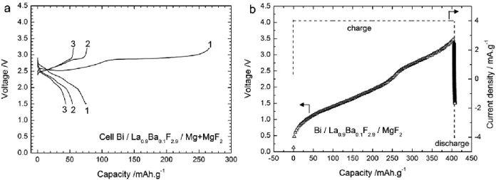
Between 1981 and 2011, not much has been done in the field of FIBs. However, in 2011 FIBs attracted some attention again, when Reddy and Fichtner reported on reversible all-solid-state conversion-based FIBs using metal/metal fluoride electrode materials along with Ba doped LaF3
(La1-xBaxF3-x) as a solid-state electrolyte. They were able to operate FIBs at elevated temperatures
(~ 150 – 200 °C) with comparatively short life cycling performances. This study opened new horizons for battery technologies by introducing new battery chemistry. The cathodic and anodic reactions during discharging of a cell can be written as follows (also see Figure 2):
At cathode side: xe− + MFx ⟶ M + xF−;
At anode side: xF− + M´ ⟶M´Fx + xe−.
Figure 2. A schematic illustration of the metal/metal fluoride conversion based FIB proposed by Reddy and Fichtner8. In that study, it was shown that doping of Ba into tysonite-type LaF3 results in a significant increase
Page 6 of 52
that this increase is necessary to obtain current densities reasonable high to achieve C-rates of ~ C/25 to C/50 to make testing at lab scale feasible. Results suggest that La0.9Ba0.1F2.9, which was
produced by mechanochemical milling of BaF2 and LaF3, has the highest ionic conductivity among
all other La1-xBaxF3-x (0 ≤ x ≤ 0.15) compounds (about 2.8 ⨯ 10-4 S/cm at 160 °C)8 with a good
electrochemical stability due to the low electrochemical potentials of Ba2+ and La3+. Various metal
fluorides including CuF2, BiF3, SnF2, and KBiF4 were tested as cathode materials against Ce metal
to make all-solid-state FIBs in their charged states. Since most of the electrode materials (e.g., BiF3 and CuF2) suffered from low ionic and electronic conductivity, they were mixed with the solid
electrolyte and carbon for better electrochemical performance, and their conversion between the metal and metal fluoride state could be well confirmed with diffraction studies.
After this proof-of-concept paper, research on FIBs has gained increased attention over the last years, with studies appearing in the field of electrolyte (solid and liquid), electrode (conversion and intercalation), and cell design development. In the following, we will summarize the attempts that have been made together with the key findings.
4
Solid Electrolytes for FIBs
Solid-state batteries have certain advantages compared to corresponding liquid electrolytes batteries, particularly concerning safety. To operate solid-state batteries, solid electrolytes (SEs) are required. Interestingly, fluoride ions show a high mobility in the solid-state. Though the ionic size of F- is large (~ 1.33 Å)19 it shows significant high mobility in solids, due to its monovalency
and high charge density. Indeed, there are several solid fluoride conducting electrolytes that show significantly high conductivities at RT. For example, PbSnF4 has an ionic conductivity of 1⨯10-3
S/cm at RT, which is well beyond the garnet based solid electrolytes for LIBs.20 Apart from a high
ionic conductivity, the electrolyte in a battery should fulfill certain criteria: Suitable electrolyte candidates must exhibit high ionic conductivity with a negligible electronic conductivity to avoid self-discharging of the cell.21 They should possess a high electrochemical stability window, i.e.,
they must be electrochemically stable within the operating voltage of the cell. The electrolyte must be chemically compatible with the electrode materials (cathode and anode) to ensure fast ion transport of the charged species across the interfaces, which does not only require stability towards redox reactions, but also an ion exchange within acid-base type of reactions. Further, SEs should possess certain mechanical properties, e.g., sufficient flexibility and softness, required for the fabrication of a solid state battery.
Most of the studies on fluoride-conducting electrolytes were carried out on single crystals. Some of the fluoride conducting single crystals show a high ionic conductivity. For example, barium doped lanthanum fluoride shows a fluoride ion conductivity in the order of 10-4 S/cm, which is
suitable to operate solid-state batteries with respect to the commonly encountered aspect ratios and charging/discharging rates. However, single crystals are expensive, difficult to grow and they are difficult to be integrated into an all-solid-state battery configuration. Thus, polycrystalline solid electrolytes are a more appropriate and realistic option. However, ionic transport in polycrystalline materials is significantly different due to the presence of grain boundaries (GB) and an increase in surface to volume ratio. Thus, ionic transport mechanisms are more complex in nanocrystalline samples due to the surface charge regions.
Page 7 of 52
In solid electrolytes, ionic transport generally depends on the structural framework, the intrinsic mobility of conducting ions and their thermal activation, the concentration of intrinsic and/or extrinsic defects, and further on the crystal field impact of the mobile ions. Ion diffusion mechanisms are mostly based on Schottky and anti-Frenkel point defects, comprising the vacancy mechanism, interstitial mechanism, and interstitial–substitutional exchange mechanism.22 However, some materials with fluorite or tysonite type structure can achieve high
ionic conductivities without a high defect concentration.23, 24 Geometric frustration from size
mismatch of the cation lattice was recently also discussed to play an important role for the conductivity of multinary fluorides with fluorite type structure.25 In general, only a few stable
fluorides exhibit significant ionic conductivity, while being insulators for the transport of electrons due to a wide bandgap.
Different fluoride conducting solid-electrolytes were reported in the literature. These solid electrolytes can be broadly categorized into two classes of compounds: tysonite-type (LaF3
prototype) and fluorite-type (CaF2 prototype). A considerable number of possibilities to achieve
improved solid-state electrolyte/separator approaches for FIBs have been developed and will be addressed in this chapter. Different materials are discussed and grouped according to their structure type (e. g., rare-earth fluorides (tysonite-type structure) doped with alkaline-earth or alkaline-earth fluorides (fluorite-type structure) doped with rare-earth fluorides). This discussion also comprises further design aspects, such as the creation of surface defects by vapor pressure treatment (CaF2-Hum), grain boundary activation using Lewis acids (BF3), or critical geometry
frustrations due to crystal deformations by multiple-phase systems.
Design of all-solid-state cells used for FIBs
FIBs have often been made in an all-solid-state modification. For all-solid-state FIBs, the most popular strategy is to make bulk pellets by cold (uniaxial) pressing of the powder precursors (cathode/electrolyte/anode). For this approach, it is important to note that most of the used active electrode materials for FIBs suffer from low electronic and ionic conductivity. For the powder-based electrodes, a suitable electron conduction pathway needs to be provided, which is commonly achieved by additives such as carbon black, graphite, nanotubes, metal surplus, etc.23, 26 The ionic conductivity is increased by the introduction of electrolyte materials. In most studies,
the FIB active electrode materials are mixed with the electrolyte material and carbon black or nanotubes to form composite electrode materials.8, 23, 26-28 Ball milling is by far the most used
technique to prepare the composite electrodes and solid-state electrolytes. For the assembly of all-solid-state battery cells, Swagelok-type electrochemical cells are very common.8, 23, 29 Figure 3
represents a typical Swagelok-type cell. Due to the low ionic conductivity of the most solid-state electrolytes for FIBs, the electrochemical cell setup should be heated often up to 150 – 200 °C, and the cell-design helps to protect the Teflon-based sealings from plastic deformation or heat-induced degradation. Recently thin-film strategies have also been introduced to make FIB cells. For instance, Zhang et al. reported30 on implementing a thin-film of Ba doped LaF
3 electrolyte by
spin coating technique on a CaF2 or MgF2 anode composite as a substrate. Further, coin cell
based systems were proposed by Grenier et al., where a high temperature stable epoxy resin can be used for sealing, facilitating improved longer-term operability.31
Page 8 of 52
There also exist some reports32, 33 on FIBs, which are based on liquid electrolytes, which can then
be investigated in the most common Swagelok-type setup. For instance, Davis et al. reported33
on standard three electrode systems for FIBs based on a liquid electrolyte. In this study, copper nanoparticles or Cu@LaF3 core-shell nanoparticles were made into a paste with polyvinylidene
fluoride (PVDF) to prepare the working electrode platinum, and silver wires were used as the counter electrode and reference electrode, respectively. Moreover, bismuth, lead, cerium and calcium thin strip foils were used as the working electrode.
Figure 3. A schematic of a high-temperature cell used for the electrochemical measurements conducted on all-solid-state FIBs.The figure has been reproduced from ref. 34.
Ionic conductivity of rare-earth fluorides with tysonite-type structure
Tysonite-type RE1-xMxF3-x (RE = La, Ce, Sm, and M = Ba, Ca, Sr) fluorides are promising as SEs
for FIBs as they show high ionic conductivities and large electrochemical stability window.8, 35 In
an undoped state, rare-earth fluorides show insufficient conductivities even for lab-scale operation. To improve the ionic conductivity in solid-state electrolytes defects are introduced into the crystal structure by increasing the concentration of mobile ionic species via aliovalent doping. It was shown that the doping of LaF3 by BaF2 enables the creation of fluoride vacancies.36 These
F vacancies promote a higher ionic mobility within the fluoride sublattice, leading to an increase of the fluoride conductivity by two orders of magnitude as compared to the stoichiometric compound.37 Thus, the conduction mechanism in tysonite-type structures relies on a purely
vacancy-type mechanism due to Schottky defects.22, 38, 39 Reddy and Fichtner used Ba-doped La 1-xBaxF3-x (0 ≤ x ≤ 0.15) (LBF) as the SEs in FIBs in theirinitial studies (Figure 4a). They found a
maximum conductivity for La0.9Ba0.1F2.9. Further, LBF prepared by high energy ball milling method
can be improved via sintering at high temperature.8, 39, 40 The ionic conductivities of compacted,
unsintered La0.90Ba0.10F2.90 (1.6 × 10⁴ S·cm1 at 160 °C) can be significantly improved by a further
sintering step at 800 °C for 2 h to 105 S·cm1 at room temperature (Figure 4b). This observation within tysonite-type LBF fluoride ion conductors is explained by the differences in the grain boundary structure, which can result in a partial blocking of the migration pathways, and has been observed for various anion conducting compounds.41 Thus, sintering treatments are viable
Page 9 of 52
acknowledging that the grain boundary influence can be compensated without increasing the grain size: In the case of a co-precipitated electrolyte, a slight increase of conductivity was attributed to reduced amounts of impurities during the synthesis process as compared to mechanical milling.42
In 2017, Chable et al. investigated the ionic conductivity of La1-xBaxF3-x (LBF) synthesized by
various methods, among them high-temperature solid-state reactions under inert atmosphere. 43
It was found (see Figure 4c) that the ionic conductivity at room temperature for the Ba-doped samples (≈ 6 ×10⁵ vs.104 S·cm1 at RT for La0.93Ba0.07F2.93) approaches the limit of the single
crystalline state of pure LaF3.44 The observed conductivity was two orders of magnitude higher
than observed earlier on cold-pressed pellets, with activation energies between 0.2 and 0.4 eV.43
Still, compositional dependence is maintained, with the maximum conductivity at room temperature for a composition close to x=0.05 – 0.07 (see Figure 4d).43 In addition, the compacted
La0.95Ba0.05F2.95 samples were tested and compared to powders that underwent the process at
900 °C with different combinations of cold uniaxial pressing and cold uniaxial plus isostatic pressing. From these experiments, the authors conclude that rare earth fluorides should be treated by a sintering process before or after the ball-milling to improve the ionic conductivity.
Page 10 of 52
Figure 4. (a) and (b) Arrhenius plots of the ionic conductivities of La1-xBaxF3-x. Parts (a) and (b) are reproduced from
ref.36 with permissionii. (c) and (d) La
1xBaxF3x (x= 0.03,0.05, 0.07, 0.1) samples after cold-uniaxial pressing, cold
isostatic pressing, and sintering of the pellets. Parts (c) and (d) are reproduced from ref.45 (an original RSC publication).
In part (d) the blue and green lines from the single crystal of La1xBaxF3x (x= 0.07, 0.1). Different pressing method
applied for the La0.95Ba0.05F2.95 sample for the ionic conductivity for uniaxial pressed pellet, a uniaxial,
cold-isostatic pressed pellet and a sintered pellet are reported.
Zhang et al.46 investigated the ionic conductivity of La
1-xBaxF3-x(0 ≤ x ≤ 0.15) thin-films synthesized
by a sol-gel assisted spin coating method based on mixtures of metal trifluoroacetate salts. They observed that the conductivity of the thin films could be significantly improved by increasing the sintering temperature and time. The conductivity value of the film was 1.6 × 10⁴ S·cm1, a significant improvement in comparison to porous films 35, 46, and an optimized thermal treatment
condition was determined to be at 450 °C for 4h. When compared to the bulk-type electrolyte, the overall conductance of the film was improved by a factor of ~ 65. The thin film morphology is of special importance, since the overall resistance was significantly reduced due to the low thickness of the thin films. A comparison shows that the conductance of a bulk type electrolyte at 170 °C is similar to that of a thin-film electrolyte at 80 °C, which could help to build all-solid-state fluoride ion batteries working at more viable conditions.35
Not only lanthanum-based fluorides can be used as a solid electrolyte. Dieudonné et al. investigated the ionic conductivity of SrF2 doped CeF3 (Ce1-xSrxF3-x), synthesized by solid-state
reaction at 900 °C for 24h.47 A high ionic conductivity of 3×10⁴ S·cm1 was obtained for
Ce0.975Sr0.025F2.975 at RT, which is close to the conductivity of a corresponding single crystal and
better than previously reported fluoride compounds.47 At room temperature, the ionic conductivity
observed in various fluorides adopting the fluorite-type structure reached a maximum value at x
Page 11 of 52
= 0.025 with one of the lowest activation energies of 0.31 eV. The Sr2+ substitution for Ce3+ ions
in this network associated with the creation of anionic vacancies modifies the fluoride ion mobility drastically. A maximum F conductivity for x = 0.025 corresponds to the largest difference in bond distances between the F2 (4d site) and F3 (2a site) ion to the surrounding Sr/Ce ion and the highest buckling of the RE1−xAExF3−x layers, which appears to result in low activation energy in
addition (Figure 5a). They further concluded that in tysonite-type RE1−xAExF3−x (RE = rare-earth
and AE = alkaline-earth) the difference in the ionic sizes of the host element (RE) and the dopant (AE) plays a vital role for achieving high ionic conductivity: When the ionic sizes are comparable, the conductivity reaches to the maximum at a low substitution rate due to network relaxation of the RE1−xAExF3−x slabs in competition with the chemical pressure, which leads to a strong variation
of sheet thickness.
Further detailed investigations have been carried out on tysonite-type Ca-doped SmF3, Sm 1-xCaxF3-x (0.05 ≤ x ≤ 0.17) again by Dieudonné et al.48 The SEs were prepared using solid-state
synthesis followed by sintering at 1000 °C. Analysis of the XRD data showed a reduction in the unit cell volume with an increasing amount of Ca dopant. This volume reduction of the cell has been attributed to the creation of anionic vacancies that decrease cationic coordination, and could further be explained by increased cation repulsion due to the loss of shielding. The best ionic conductivity as high as 1.0⨯10-4 S cm-1 was obtained for Sm
0.95Ca0.05F2.95 at RT. In Sm1−xCaxF3−x,
the difference (+0.05 Å) of ionic radii for nine-fold coordination between Ca2+ (1.18 Å) and Sm3+
(1.13 Å) leads to a predominant influence of the network relaxation with a decrease of cell volume related to segregation of anionic vacancies. Both the thickness of [Sm1−xCaxF3-x] layers (≈ 1.20 Å)
and the ionic conductivity are maximal for a composition of x = 0.05. This observation was explained by a modification of the fluorine environments and segregation of the vacancies around the calcium by increasing the x values. In contrast, for La1−xBaxF3−x, the large difference of cationic
radii (+0.25 Å) introduces a significant chemical pressure and microstrain together with a significant increase in the cell volume. Comparison with La1−xBaxF3−x, Ce1−xSrxF3−x, and
La1−xSrxF3−x, shows that the higher the buckling effect of RE1−xAExF2−x, which affects the distortion
of the F1 site, the higher the ionic conductivity. This explains the evolution with x of the RT ionic conductivity of different solid electrolytes (Figure 5b), which hardly correlates with simple volume changes only. They suggested that a moderate ionic radii difference serves to optimize the ionic conductivity: Y-Ca, Eu-Ca and Gd-Ca could fulfill this requirement. However, there are no experimental results on the suggested systems so far. Most recently, Sm1-xCaxF3-x solid
electrolytes were prepared by high-energy planetary ball-milling as an alternative method and studied with NMR by Molaiyan et al.49, which helped to correlate the ionic conductivity to the
Page 12 of 52
Figure 5. (a) The crystal structure representation of the tysonite-type structure. (b) Impedance plot and complex fits of the Sm0.95Ca0.05F2.95 at room temperature. (a, b: Reproduced from ref. 48 with permissioniii) (c) Variation of the ionic
conductivity vs temperature for Ce1−xSrxF3−x (x = 0, 0.01, 0.025, 0.05, 0.07, 0.10). (d) Evolution with x of the room temperature ionic conductivity of RE1xAExF3x (RE= La, Ce, Sm; AE= Ba, Sr, Ca). (c, d: Reproduced from ref. 47 (an
original RSC publication)).
Alkaline-Earth Fluorides with Fluorite-type Structure 4.3.1 AE1xRExF2x Compounds
Solid-state fluorite-type electrolyte systems are found at the alkaline earth richer end of the series with a general chemical formula of AE1-xMxF2x (AE = Ca, Sr, Ba; M = RE), and also for a binary
mixture between two alkaline earth fluorides. Most of these fluoride-conducting electrolytes have been synthesized by a high energy ball-milling method, e. g., for the formation of the series BaxCa1-xF2.38, 50, 51 An ionic conductivity of 1.16 ×10⁵ S·cm1 for BaxCa1-xF2 at 413 K was
reported,51 which is lower than for the tysonite type systems. Apart from isovalent doping, also
aliovalent series of BaF2 doped with LaF3 were taken into consideration.41, 52 Ba0.6La0.4F2.4 shows
the highest conductivity among the Ba1-xLaxF2+x solid solutions (Figure 6a). Ball-milling of
coarse-grained BaF2 yields a nano-crystalline sample, which shows a conductivity of almost two orders
of magnitudes higher as compared to non-milled material. The ionic conductivity can be further improved by further addition of calcium53, by which a non-equilibrium phase is obtained. In
contrast, the increase of conductivity was explained here from the increase of disorder and strain introduced when the cations are of different sizes.54, 55
Düvel et al. 56 reported a detailed NMR study of Ba
1–xLaxF2+x (0 ≤ x ≤ 1) compositions synthesized
by a ball milling method at ambient temperature. The Ba1–xLaxF2+x compounds crystallized in the
fluorite-type structure from 0 ≤ x ≲ 0.775, with phase mixtures beyond this range and tysonite-type structures for x > 0.85. From x ≈ 0.70 to x ≈ 0.85, the NMR spectra indicate structural aspects of both crystal structures, though there is still a decrease of the chemical shift of the fluoride ions on the F2/3 sites with increasing BaF2 content (Figure 6b). The authors showed that changes of
chemical shifts associated with the structural transition can be correlated with the transitions in the bond distances d(M–F). Further, there seems to be an intrinsic change of bonding to the F1
Page 13 of 52
ion in the range from x = 0.55 to x = 1 making the fluoride site in the fluorite-type structure more similar to the F1 ion in the tysonite-type structure (Figure 6b).
Figure 6. (a) Ionic conductivity for Ba1–xLaxF2+x (0 ≤ x ≤ 0.55) solid solutions in comparison with ball-milled and single
crystals of Ba1–xLaxF2+x.The best performance of ionic conductivity was reported for the sample x = 0.40. (Reproduced
from ref. with permissioniv). (b) 19F Nuclear Magnetic Resonance (NMR) studies reported for the chemical shift changes
of Ba1-xLaxF2+x with x. The red points indicate that the fluoride ions on the anion site in the fluorite-type structure and
F1 sites in the tysonite structure appear to show a transition between each other. The NMR lines of Ba1–xLaxF2+x (x ≥
0.80) corresponding to F1 on F2 and F3 sites with the tysonite-type structure as blue rhombs. (Reproduced from ref. 56
with permissionv).
4.3.2 Tetragonal BaSnF4 and Interlayer Electrolytes (La0.9Ba0.1F2.9/BaSnF4)
SnF2 containing compounds like MSnF4 (M = Pb, Ba, Ca, Sr) can show ordering between the M
and the Sn site cations in an otherwise fluorite-type structural setting. Such ordering can lead to a high conductivity even at room temperature.57-59 The high ionic conductivity in SnF
2 containing
compounds results from the presence of the 5s2 lone pair on the Sn2+ atom, which requires space
(the lone pair is known to require as much space as a fluoride ion itself60, 61). This strongly distorts
the fluoride sublattice in combination with the ordering of cations. The crystal structure of tetragonal BaSnF4 (Figure 7a) can be derived from the cubic fluorite-type structure by ordering of
the Sn and Ba cations in Sn-Sn, Ba-Sn, and Ba-Ba layers, along the c-direction of the tetragonal cell. This ordering results in three different fluoride sites, termed as F1 (3/
4, 1/4, 0.19), F2 (3/4, 1/4, 1/
2), and F3 (1/4, 1/4, 0.68), and they reside in Sn-Sn, Ba-Sn, and Ba-Ba layers, respectively. The
stereoactive lone pair induces a repulsive interaction between the lone pair electron and negatively charged fluoride ion, which leads to a depletion of the fluoride ions in the Sn−Sn and Sn−Ba layers of the BaSnF4 crystal structure. Hence, the fluoride ions between Sn and
Sn-Ba layers become mobile since the lone pair is polarizable and can reorient on movement, thus becoming involved in the conduction process. The ionic conductivity of BaSnF4 is in the order of
1 ×10⁴ S·cm1 at RT.62 Interestingly, its cold-pressed powders also exhibit high conductivity at
RT, which makes it suitable candidates as solid electrolytes for fluoride ion batteries. Recently,
iv Copyright © 1999 American Institute of Physics v Copyright © 2014 American Chemical Society
Page 14 of 52
Mohammad et al. have demonstrated rechargeable RT-FIBs utilizing BaSnF4 as a solid electrolyte 63, where the electrode materials were chosen to take into account the limited electrochemical
stability of the electrolyte. The ionic conductivity of 3.5 10−4 S·cm−1 at RT for the electrolyte (see
Figure 7b) can be sufficient for RT fluoride-ion battery applications. The cells were based on BaSnF4 as the electrolyte, BiF3 as the cathode, and Zn or Sn as the anode. The electrochemical
results on Zn/BaSnF4/BiF3 cell are displayed in Figure 7c,d. The cyclic voltammetry profile of the
cell features a cathodic and anodic peak confirming the reduction of BiF3 and oxidation of Bi,
respectively (Figure 7c). The cell exhibits a first discharge and charge capacity of 56 and 43 mA·h·g−1, respectively (Figure 7d). At subsequent discharging and charging, the capacity is found to increase slightly, which can be explained by increased electrochemical accessibility of the Zn anode.
Figure 7. (a) Layered structure of tetragonal BaSnF4 displaying different cation layers and fluoride ions with Sn
coordination environment of BaSnF4 showing lone pairs on Sn2+ pointing in the c-direction (figure a is reproduced from
ref.57 with permissionvi; (b)Nyquist plot of tetragonal BaSnF
4 obtained at 25 °C, (c) Cyclic voltammogram profiles of
Zn/BaSnF4/BiF3 cellsobtained at 25 °C. Voltage-composition profiles of Zn/BaSnF4/BiF3 cells obtained at 25 °C
(reproduced from ref.63 with permission vii).
Currently, the low electrochemical stability of BaSnF4 limits the use of highly reductive anode
materials or highly oxidizing cathode materials, due to the fact that Sn2+ can both be oxidized or
reduced at intermediate potentials already. To build high potential FIBs, high electropositive metals (Ce, Mg, La) should be used as anodes, which are compatible with electrolytes like tysonite-type La0.9Ba0.1F2.9. La0.9Ba0.1F2.9 electrolytes with low RT conductivity (4x10⁻⁷ Scm−1). To
vi Copyright © 2002 American Chemical Society vii Copyright © 2018, American Chemical Society
Page 15 of 52
overcome these limitations of the low electrolyte stability and low ionic conductivity, Mohammad et al. developed an interlayer electrolyte concept to build high-potential RT-FIBs.64 The use of low
conductive La0.9Ba0.1F2.9 succeeded in maintaining the high total conductivity of the electrolyte,
and in physically isolating the less stable and highly conductive electrolyte (BaSnF4) from the
electropositive anode. Figure 8a shows the cross-sectional SEM image obtained for an inter-layer electrolyte pellet (20 mg of La0.9Ba0.1F2.9 and 120 mg of BaSnF4), which highlights that both layers
stick uniformly to each other without intermixing. Impedance analyses are used to investigate the conductivity and interface stability of the interlayer electrolyte as shown in Figure 8b and c. The figure compares the Nyquist plots of interlayer electrolyte with different relative thicknesses of La0.9Ba0.1F2.9 obtained at 25 °C, and show a strong difference on to which extent grain, grain
boundary and electrode responses are expressed, though the resistance appears to scale linearly with the thicknesses of the different layers. The authors conclude that with improved coating methods, it might be possible to achieve high ionic conductivities similar to that of BaSnF4 while
extending its electrochemical stability window. Electrochemical performance testing of the interlayer electrolyte was conducted using BiF3 as a cathode and Ce as an anode. The
charge-discharge profiles of the interlayer electrolyte-based cell is displayed in Figure 8d. The cell shows an open circuit voltage of 2.6 V at room temperature. It delivered a first discharge capacity of 27 mA·h·g−1 at an average voltage of 1.4 V. During the second and subsequent cycles, the discharge and charge profiles show high average voltage plateau. In the following cycling, quick capacity fading was observed, resulting in 3 mA·h·g−1 after five cycles Figure 8d).
Page 16 of 52
Figure 8. (a) Cross-sectional SEM image of La0.9Ba0.1F2.9 (20 mg)/BaSnF4 (120 mg) pellet, (b) Nyquist plots (symbols)
and the corresponding fit (lines) of La0.9Ba0.1F2.9 (20 mg)/BaSnF4 (120 mg) and La0.9Ba0.1F2.9 obtained at 25 °C, (c)
Nyquist plots (symbols) and corresponding fit (line) for La0.9Ba0.1F2.9 (10 mg)/BaSnF4 (130 mg) electrolyte obtained at
25 C, (d). Voltage-composition profiles of Ce/La0.9Ba0.1F2.9/BaSnF4/BiF3 cell obtained at 25 °C with a current density
of ±10 µA·cm−2(reproduced from ref.64 with permissionviii) .
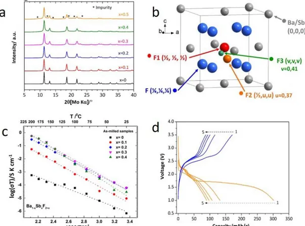
Nano-crystalline Fluorite-type Ba1−xSbxF2+x (0 ≤ x ≤ 0.4)
Besides Sn2+, there are other cations containing lone pairs of electrons such as Sb3+, Bi3+, and
Tl+, which might have a similar effect on the ionic conductivity. In an attempt to mimic the idea of
the lone pair effect for the ionic conductivity enhancement, Mohammad et al. have recently synthesized SbF3-doped BaF2 via ball-milling, assuming that ns2 configured Sb3+ might strongly
participate to an increase the ionic conductivity of BaF2.65 The doping of SbF3 in the BaF2 crystal
was limited to x ˂ 0.5, confirmed by an XRD analysis (displayed in Figure 9a). This means a comparably lower amount of SbF3 is sufficient in order to obtain a higher occupancy of the
interstitial site. In the crystal structure of Ba1−xSbxF2+x (0 ≤ x ≤ 0.4), Ba and Sb (represented in
grey) form an fcc array in which fluoride ions (represented in blue) occupy all tetrahedral sites (Figure 9b). During doping, extra fluoride ions due to the higher valancy of the dopant Sb3+ occupy
the interstitial positions such as F2 and F3. The interstitial site F1 (1/
2, 1/2, 1/2) is being occupied at
a lower concentration of the dopant, whereas the related sites with off-centre shifts, F2 (1/
2, 0.37,
0.37) and F3 (1/
2, 0.41, 0.41), are occupied at higher concentrations of the dopant. The ion
conductivity of the solid solution was increased with increasing dopant concentration, indicating
Page 17 of 52
that these off-centre shifts can be considered crucial for obtaining functional ceramics. Further, the temperature dependent evolution of the ionic conductivity of Ba1-xSbxF2+x (0 ≤ x ≤ 0.4) was
investigated (Figure 9c). By this, it was found that it can reach twice the conductivity of the isostructural Ba0.7La0.3F2.3 (1.55 ×10⁴ S·cm1 at 160 °C), meaning that the additional increment
of conductivity might result most plausibly from the stereochemical impact of the ns2 cation. The
material can also be used within a full battery against Ce anodes. Figure 9d shows the electrochemical profiles of the cell for the first five cycles, showing high electrochemical accessibility of the active electrode material of ~ 66% of the theoretical specific capacity of SbF3
(450 mA·h·g−1). However, rapid capacity fading was observed for prolonged cycling. This considerable capacity fading is probably due to large volume and structural changes in the electrode materials and not necessarily linked to the electrolyte itself.
Figure 9 (a) XRD patterns of Ba1-xSbxF2+x (0 ≤ x ≤ 0.5) compounds, (b)Representative structural view of Ba1–
xSbxF2+x (doped fluorite), (c) Arrhenius plots of the ionic conductivity of Ba1−xSbxF2+x (0 ≤ x ≤ 0.4) compounds (symbols)
and their fits (dotted lines). (d) Voltage-capacity profiles of Ba0.7Sb0.3F2.3/La0.9Ba0.1F2.9/Ce cell obtained at 150 °C with
a current density of 10 µA·cm−2 (figures are reproduced from ref.65 with permission ix). PbSnF4 based Solid Fluoride Electrolytes
In-depth investigations and improvements of the ionic conductivities of solid-state electrolytes are emerging areas of FIBs. So far, PbxSn2-xF4 (Figure 10a) is one the best superionic fluoride
conductors.6619F MAS NMR results show the that mechanochemical synthesis drives the system
mainly into the cubic β-phase, with the introduction of surface defects, which exchange with the
Page 18 of 52
nanoparticle core.66, 67 This interaction also promotes conductivities within the crystallite and at
the particle boundaries, with ion mobility at the macroscopic material level, which is in slight contrast to what is reported in previous studies.68-70 Low activation energies result in high ionic
conductivities at room temperature (Figure 10b), with values close to single crystals and better than what was found previously for fluorite type materials.71, 72 The solid electrolytes of Pb
xSn2-xF4
were also prepared by high-energy planetary ball-milling.73 Such electrolytes showed a fluoride
ion conductivity equal to that of the electrolytes synthesized using a melting method with an activation energy of 0.30 eV for x = 1.1.
Figure 10. (a) Packing of β+-PbSnF4 in the unit cell. Blue and red balls are Sn and Pb, respectively. (b) Dependence
of the conductivity at room temperature on the Pb/Sn molar ratio in the PbxSn2–xF4 pressed-powder samples (x = 0.96–
1.56) annealed at 400 °C (open circle) and 200 °C (filled circle) (figures are reproduced from ref.74 with permissionx). CaF2 based Solid Electrolytes for FIBs
CaF2 would be a cheap electrolyte material with a high electrochemical stability; however, pure
CaF2 is a bad ionic conductor, due to the hard nature of Ca2+ ion.75 Yuria Saito et al. reported that
an ionic conductivity enhancement of the CaF2 could be achieved using Lewis acids 76, but not
via the creation of grain conductivity on doping. The effect of the addition of a Lewis acid, e. g., SbF5 or BF3, on the fluoride ion conductivity in CaF2 indicated a surface activation of the particles.
The conductivity enhancement mechanism is based on the adsorption of Lewis acids, which attract fluoride ions out of the CaF2 boundary regions to create vacancies at the CaF2/SbF5 or
CaF2/BF3 interfaces, giving rise to a strong increase of the ionic conductivity. The conductivity
results based on CaF2 thin films also confirmed the presence of space-charge regions as a
consequence of the attractive forces of the adsorbed Lewis acid.76
Molaiyan et al. have recently reported that the surface activation and conductivity enhancement of calcium fluoride synthesized via ball milling is possible.77 The pure CaF
2 powder was exposed
to salt water with a relative humidity (RH) of 88%, and ball-milled subsequently. The reported ionic conductivity of synthesized humidified CaF2 electrolyte was around 1.9 ×10⁵ S·cm1 at room
Page 19 of 52
temperature. The reported values are several orders of magnitude higher than pure and ball-milled CaF2 (2 ×10⁷ to 1.6 ×10¹¹ S·cm1).78 The reported activation energy of the humidified CaF2
was around 0.35 eV, which was related to the surface formation of interstitial fluoride sites with suggested formation energies of around 0.25 eV,79, 80 making the material applicable in fluoride
ion batteries.81 The ionic conductivity increases with higher temperature up to a certain critical
temperature, after which the decomposition of the defect structure is promoted and the conductivity decreases. From this study, it can be concluded that crystal surface defects strongly influence overall bulk conductivities82, 83 and can provide an alternative route as compared to bulk
modifications84, 85.
Synthesis of Solid Electrolytes: Ball-Milling Method and other methods
Solid-state reactions generally occur at higher temperatures and often lead to powder morphologies that are unfavorable for battery cell fabrication. In favorable cases, reactions can be carried out merely by grinding the reagents via mechanochemical synthesis 86, and this method
has been widely studied for the preparation of multinary fluorides.41, 51, 56, 70, 87-90 On the lab-scale
level, such synthesis will be done with a high-energy milling method. The crystalline reagents are being impacted with the milling balls at high kinetic energies, which causes high impact energies and can reduce the crystalline regions down to nanometer size with the introduction of crystal defects also.41 Thus, mechanochemical synthesis may become an essential method for the
synthesis of new nanomaterials and nanocomposite materials, as it is a relatively cheap and energy-efficient. In addition, further advantages of mechanochemical synthesis comprise a more reliable, easy operation to ensure reproducibility and large scale synthesis. As a disadvantage, one must acknowledge that due to high-speed rotation of the vial usually for long hours, contamination might be introduced to the system. This can be even more severe for fluoride-based materials, which can be reactive towards many milling vials (e.g., silica or alumina fluoride-based materials).
As discussed in the previous section, post-ball-milling treatments such as high-temperature sintering can often be required to reach the highest ionic conductivities, where the increase of conductivity must be balanced against particle growth, which can be unfavorable for cell fabrication. The ionic conductivity is highly dependent on the microstructure of the polycrystalline material, as conduction properties are different within the grain boundaries and in bulk.91 In
polycrystalline solid electrolytes, especially when milled to the nanoscale, the conduction properties can be radically different from their single-crystalline counterparts. This is due to the fact that high amounts of grain boundaries must be surpassed and since such powders are often richer in defects.92 From a microscopic viewpoint, properties are different for the bulk, which
generally presents the same conduction properties as a single crystal, and for the surface, where many defects are present at the grain boundaries.47 While the conduction is limited by the
migration of the ionic species in the grain boundaries, if the powder processed by uniaxial pressing, the sintered samples are normally dominated by bulk conduction.93
Apart from ball-milling, only a few reports exist which emphasize on the preparation of nano-crystalline materials via other approaches. Since most electrolytes are based on alkaline earth or lanthanide metals, precipitation routes are feasible for the fabrication of nano-crystalline defect rich powders. This is based on the low solubility of these fluorides, even in an aqueous solution.
Page 20 of 52
Bhatia et al.42 found that this fabrication method can give similar properties as the ball-milling
procedure. Due to the similar solubility of LaF3 and BaF2, this method can be even used for the
preparation of mixed crystals of higher complexity, such as La1-xBaxF3-x. Further, up-scaling of
powder production could also be considered easier for wet-chemical approaches in contrast to milling based reaction routes.
Temperature-dependence of Fluoride conducting Materials – A comparison
From the early days until now, the detailed understanding of structural and conductivity features of inorganic fluorides has opened the path for the development of many solid fluoride electrolytes with improved ionic conductivity and their use in lab-scale batteries in various electrochemical studies. In a nutshell, the doping of pure fluoride electrolytes with aliovalent fluorides (e.g., BaF2
-doped LaF3, KF-doped β-PbF2 or BiF3-doped β-PbF2) leads to an increase in the ionic conductivity
of the doped material due to the creation of fluoride point defects most often. Defects present in the crystal structure provide fast diffusion pathways for fluoride ions and result in the conductivity enhancement required to obtain reasonable charging times. An overview of ionic conductivities reported previously for a variety of materials is given in Table 1.
Page 21 of 52
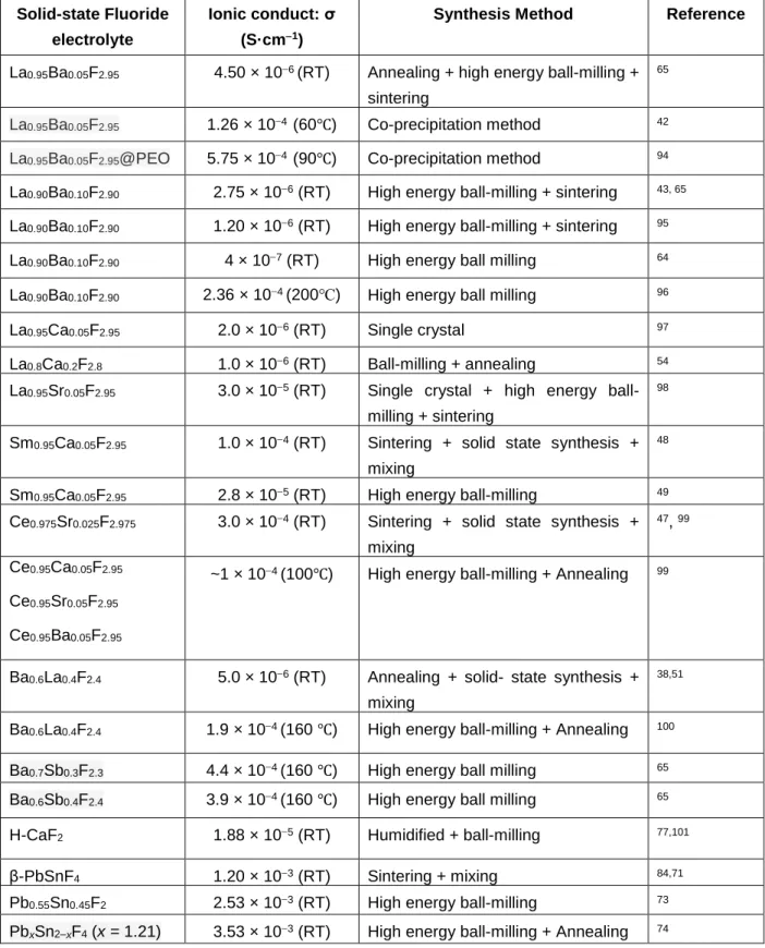
Table 1. Summary of synthesis methods for different Solid-state fluoride electrolytes. RT refers to room temperature.
Solid-state Fluoride electrolyte
Ionic conduct: σ (S·cm1)
Synthesis Method Reference
La0.95Ba0.05F2.95 4.50 × 10⁶(RT) Annealing + high energy ball-milling +
sintering
65
La0.95Ba0.05F2.95 1.26 × 10⁴ (60℃) Co-precipitation method 42
La0.95Ba0.05F2.95@PEO 5.75 × 10⁴ (90℃) Co-precipitation method 94
La0.90Ba0.10F2.90 2.75 × 10⁶ (RT) High energy ball-milling + sintering 43, 65
La0.90Ba0.10F2.90 1.20 × 10⁶ (RT) High energy ball-milling + sintering 95
La0.90Ba0.10F2.90 4 × 10⁷ (RT) High energy ball milling 64
La0.90Ba0.10F2.90 2.36 × 10⁴ (200℃) High energy ball milling 96
La0.95Ca0.05F2.95 2.0 × 10⁶ (RT) Single crystal 97
La0.8Ca0.2F2.8 1.0 × 10⁶ (RT) Ball-milling + annealing 54
La0.95Sr0.05F2.95 3.0 × 10⁵ (RT) Single crystal + high energy
ball-milling + sintering
98
Sm0.95Ca0.05F2.95 1.0 × 10⁴ (RT) Sintering + solid state synthesis +
mixing
48
Sm0.95Ca0.05F2.95 2.8 × 10⁵ (RT) High energy ball-milling 49
Ce0.975Sr0.025F2.975 3.0 × 10⁴ (RT) Sintering + solid state synthesis +
mixing
47, 99
Ce0.95Ca0.05F2.95
Ce0.95Sr0.05F2.95
Ce0.95Ba0.05F2.95
~1 × 10⁴ (100℃) High energy ball-milling + Annealing 99
Ba0.6La0.4F2.4 5.0 × 10⁶ (RT) Annealing + solid- state synthesis +
mixing
38,51
Ba0.6La0.4F2.4 1.9 × 10⁴ (160 ℃) High energy ball-milling + Annealing 100
Ba0.7Sb0.3F2.3 4.4 × 10⁴ (160 ℃) High energy ball milling 65
Ba0.6Sb0.4F2.4 3.9 × 10⁴ (160 ℃) High energy ball milling 65
H-CaF2 1.88 × 10⁵ (RT) Humidified + ball-milling 77,101
β-PbSnF4 1.20 × 10³ (RT) Sintering + mixing 84,71
Pb0.55Sn0.45F2 2.53 × 10³ (RT) High energy ball-milling 73
Page 22 of 52
5 Liquid and Polymer-based Electrolytes for Fluoride-Ion Batteries
Fluoride ion batteries have been studied mostly using solid electrolytes, mainly leading to operating temperatures of 150 °C or even above. However, more and more reports have been demonstrating the fluoride ion battery concept using a liquid electrolyte in very recent years. The preparation of liquid electrolytes for FIBs is significantly different as compared to LIBs. For Li-ion batteries, liquid electrolytes typically consist of simple lithium salts such as LiPF6 or LiClO4
in organic solvents. However, this cannot be mimicked for fluoride ion batteries because simple fluoride salts such as KF and CsF are almost insoluble in organic aprotic solvents. So far, two strategies were adopted to prepare fluoride ion conducting liquid electrolytes: The first one is by dissolving fluoride salts in organic solvents, and the second one is by mixing organic fluorides into ionic liquids (ILs). For the latter, only one patent has claimed the fabrication of a FIB cell using an IL based electrolyte, which was composed of tetramethylammonium fluoride (TMAF) and 1-methyl-1-propylpiperidinium bis(tri-fluoromethanesulfonyl)imide (MPPTFSI).102 The assembled
cell showed an electrochemical performance for two cycles with an initial capacity of 103 mAh g -1, but the structural data of electrodes before and after discharge was not reported. To date,
several patents have been reported, claiming the feasibility of FIBs containing a liquid electrolyte.103-106 Thus, several attempts have been made in order to develop liquid fluoride
conducting electrolytes and test them in battery setups. In an initial report, Gschwind et al. prepared a non-inorganic electrolyte based on ammonium bifluoride-doped polyethylene glycol (PEG) matrix.32, 107 Their objective was to form a hydrogen-bonded PEG matrix to trap difluorides
for fluoride conduction. Figure 11a shows a schematic drawing of the possible hydrogen bonding, which could be expected in a polymer electrolyte containing bifluoride ions (FHF−). The electrolyte showed an ionic conductivity of 2.1 mS cm-1 at room temperature for an optimized concentration
of 0.02 M. The assembled cell with BiF3 as the cathode, Mg as the anode and this polymer
electrolyte showed a good first discharge capacity. However, it fails to deliver any reversible capacity (Figure 11b). To find the exact reason of the non-reversibility of the cell, SEM analysis was performed on the Mg electrode before and after discharging, which reveals a snowflake-like formation of MgF2 layers on the Mg surface.107 This is a very poor ionic conductor and acts as a
passivation layer for F− diffusion, and can be considered as the main reason for irreversibility. Recently, a new fluoride ion-conducting polymer system consisting of poly(ethylene)oxide (PEO), metal fluoride salts, and anion acceptors has been reported.108 The polymer electrolyte exhibited
the ionic conductivity of 1 × 10⁶ S cm−1 at 303 K, with fluoride transference numbers as large as 0.8. A FIB utilizing a liquid electrolyte for fluoride transport was reported recently by Ogumi et al., where the electrolyte was made from mixing an organic fluoride (1-methyl-1-propylpiperidinium
fluoride: MPPF) in an ionic liquid (N,N,N-trimethyl-N-propylammonium
bis(trifluoromethanesulfonyl)amide: TMPA/TFSA).109 The electrolyte shows a conductivity of
2.5 mS cm−1 at room temperature for a concentration of 0.35 M. The electrochemical stability of the electrolyte was investigated by cyclic voltammetry using Pt or Bi as working electrode, and a fluorinated Pb plate as counter and reference electrode (Figure 11c), indicating a small electrochemical stability window of 0.7 V vs Pb/Pb2+. The full cell assembly utilizing the electrolyte
showed significant charge and discharge capacities for few cycles at low operating voltage (~ 0.2 V) (Figure 11d).
Page 23 of 52
Figure 11 (a) A schematic drawing of possible hydrogen bonds, which could occur in a hydrogenbifluoride-doped PEG matrix (reproduced from ref.32 (an original RSC publication)), (b) Discharge curves of BiF
3 against Mg using PEG matrix
based electrolyte with three different separators (reproduced from ref.107 (an original RSC publication)), (c) CVs of the
Bi and Pt electrodes in ∼ 0.07 mol.dm–3 MPPF/TMPA-TFSA at a scan rate of 1.0 mV.s–1 (Blue lines: Bi. Gray lines with
circles: Pt), (d) Cycling test of the bismuth electrode in ∼ 0.35 mol dm–3 MPPF/TMPA-TFSA at current densities of 20
μA.cm–2 (parts b and c are reproduced from ref.109 with permissionxi).
Later, the same group has further developed FIBs by introducing a new type of electrolyte synthesized by dissolving a fluoride salt in an organic solvent with the help of an anion acceptor.110
The idea was to develop an electrolyte that can dissolve and deposit the active material to facilitate the electrochemical reaction of FIBs. The electrolyte solution was prepared by using bis [2-(2-methoxyethoxy) ethyl] ether (tetraglyme:G4) as the solvent containing 0.45 M cesium fluoride (CsF) with addition of 0.5 mol L−1 of a boron-based ion anion acceptor (fluorobis (2,4,6-trimethylphenyl) borane: FBTMPhB). The anion acceptor was added mainly to enhance the solubility of CsF in the tetraglyme solvent by reducing the cation-anion interaction between Cs+
and F-. DFT calculations confirm the capability of FBTMPhB as anion acceptor to bind fluoride
ions. Figure 12a shows the most stable binding site for the fluoride ion at the boron atom. The electrochemical stability of this liquid electrolyte was investigated by cyclic voltammetry (displayed in Figure 12b), where the CsF(0.45)-FBTMPhB(0.5)-G4 composition shows a stability window between -2.2 to -0.3 V vs. Ag/Ag+. Furthermore, the performance of this electrolyte was
demonstrated in a FIB half cell constituting of BiF3 as a working cathode and a Pt mesh as a
counter electrode. The cell delivered a first discharge capacity of 316 mAh g-1 (slightly higher than
Page 24 of 52
the theoretical capacity, indicating some side reactions), but in the subsequent cycles the capacity faded rapidly and decreased close to zero after 10 cycles. The electrochemical performance of PbF2 as an active material has also been investigated within a FIB system with the same liquid
electrolyte.111 In this work, the discharge capacity reduced to almost half only after three cycles,
though, the XRD measurements confirm occurrence of the charge/discharge reactions within the second and third cycles.
Later, the effect of two other boron-containing compounds, triphenylboroxine (TPhBX) and triphenylborane (TPhB), as anion acceptors was investigated.112 The authors concluded that the
addition of TPhBX and TPhB can significantly increase the solubility of CsF in G4. Still, a significant capacity fading (from ~350 mAh g-1 in the first cycle to ~75 mAh g-1 in the third cycle
for CsF-TPhB-G4) can be observed during the cell operation. A similar argument holds true when PbF2 is used as the electrode material instead of BiF3.113 This poor behavior of TPhBX has been
related to the dissolution of Bi114 and Pb113 ions. It is also shown that the amount of CsF in the
solution can influence the cycling stability: The discharge capacity of the system based on the electrolyte with G4 containing saturated CsF and 0.50 M TPhBX can increase the discharge capacity of BiF3 in the second and third cycles to almost 100 % as compared to that within the
system based on the electrolyte with G4 containing 0.45 M CsF and 0.50 M TPhBX.114 In the
same system, other factors such as microparticulation of the BiF3 and adhesion of the conductive
material to BiF3 by ball milling were investigated later, showing that while reducing the particle
size only slightly affects the practical capacity, adhesion of the BiF3 to carbon particles can
significantly increase the charge/discharge capacities.115 To further improve the cycling
performance, a PbF2 electrode was later used by the same research group to build up a FIB cell
based on bis[2‐(2‐methoxyethoxy)ethyl] ether containing cesium fluoride and TPhB as the electrolyte.116 This resulted in a better capacity retention during the first three cycles (~210 mAh
g-1 and ~100 mAh g-1 at the first and third cycles, respectively) as compared to that with BiF 3 as
the electrode material.117, 118 In another study,119 PbF
2 has been investigated using a similar
liquid-based electrolyte but with the addition of TPhBX as the anion acceptor. There, the effects of pulverization of PbF2 and carbon additive were elaborated and the authors conclude that a mixture
of PbF2 and carbon, which is pulverized by ball milling, can increase the capacity of the cell.
A liquid fluoride conducting electrolyte with high ionic conductivity and wide electrochemical stability was designed and developed by Davis et al.33 A highly concentrated (˃2.2 M) electrolyte
was synthesized by dissolving dry N,N,Ntrimethyl-N-neopentylammonium fluoride (Np1F) in the organic solvent Bis(2,2,2-trifluoroethyl) ether (BTFE) (Figure 12c). They also investigated the solubility of Np1F in several non-aqueous solvents in order to find suitable electrolyte for FIBs.120
The 0.75 M Np1F/BTFE electrolyte, in particular, displays ionic conductivity of 7.95 mS cm−1 at room temperature. The electrochemical stability window of 0.75 M Np1F/BTFE electrolyte was determined by linear sweep voltammetry, showing a potential window between 0.7 V (cathodic voltage limit) and 4.8 V (anodic voltage limit) versus Li+/Li (Figure 12d). However, the
electrochemical cycling of various metallic electrodes (such as: Cu, Pb, Bi, Ce and Ca) revealed that there is a considerable amount of metal dissolution into the electrolyte, which leads to poor performances. To avoid the electrolyte breakdown due to direct contact with the metal, a fluoride conductive layer protecting the electrode materials was introduced. The Ce electrode was engineered with a fluorinated solid electrolyte interphase (SEI) layer, whereas Cu particles were encapsulated in a thin layer of LaF3 in a core-shell setup, referred to as Cu@LaF3. The fabricated
Page 25 of 52
cell comprised of the modified electrodes and the liquid electrolyte was cycled reversibly at room temperature with a reversible capacity of around 60 mAh g−1, which is 8 times less than the theoretical capacity of CuF2 (528 mAh g−1), meaning an incomplete reaction occurred at the
electrodes. Another report describes a new electrolyte based on fluorohydrogenate ionic liquid [C2C1im][(FH)2.3F] (C2C1im = 1-ethyl-3-methylimidazolium), with an ionic conductivity as high as 100 mS cm−1 at 25 °C.121 Here, the FIB cell with CuF
2 cathode delivered an excellent first
discharge capacity of 500 mAh g−1, which is close to the theoretical capacity of CuF2. The
reversible capacity reaches to 475 mAh g−1 during the first cycle, resulting in a Coulombic efficiency of 92 %, which is already higher than the value observed in previous reports. In the following cycles, the performance of the cell degraded gradually; as result, the 10th reversal
capacity reaches to 264 mAh g−1. Thus, one can conclude that realizing full utilization of active material at room temperature is a very challenging task, whose implementation requires the development of other electrolytes.
Apart from using organic solvents to develop liquid electrolytes for FIBs, aqueous solutions have also been considered for the same purpose. For instance, cells based on fluoride and sodium ion (dual) transfer were proposed by Zhang et al.122 In their study, aqueous sodium fluoride was used
as a liquid electrolyte while BiF3 and sodium manganese oxides (NMO) were used as the positive
and negative electrodes, respectively. The cell delivered a reversible and stable discharge capacity of 47.3 mAh g−1 after 40 cycles. A NaF salt solution has also been used as a liquid electrolyte to build up a FIB cell by Hou et al.123 In this study, BiF
3 has been used as an anode
and cycled against a 4-hydroxy-TEMPO cathode, i.e., a persistent radical that is sterically protected by four α-methyl groups and undergoes one electron oxidation.123 The electrodes were
implemented as a paste (slurry method) on graphite paper and a high-quality anion exchange membrane was used to prevent side effects of insoluble compounds ensuring only fluoride ions are transported during the operation of the cell. Here the results show stable cycling performance at least for 85 cycles with a reversible capacity of around 90 mAh g-1. However, a relatively large
voltage hysteresis (~ 1.0 V on average) can be observed.
A summary of the reported liquid electrolytes and their electrochemical properties can be found in Table 2.
Page 26 of 52
Figure 12. (a) Optimized molecular structure of FBTMPhB−F−, (b) Cyclic voltammograms of the
CsF(0.45)-FBTMPhB(0.5)-G4 (parts a and b are reproduced from ref.110 with permissionxii); (c) Simulated solvation shell of BTFE
molecules surrounding F– (pink sphere) (d) Linear sweep voltammograms for 0.75 M Np1F in BTFE, collected using a scan rate of 1 mV.s–1. (parts c and d are reproduced from ref. 33 with permissionxiii)
Table 2. Liquid electrolytes for FIBs and their electrochemical property. Electrolyte Conductivity (mS cm-1) Stability-Window (V) Capacity (first discharge) Ref. 0.1M TMAF/MPPTFSI 1 -3.5 to 4.0 (vs Ag/Ag+) 103 mAh g-1 102
0.02M FHF doped PEG 2.1 - 250 mAh g-1 32
0.35M MPPF/TMPA-TFSA 2.5 0 to 0.7 (vs Pb/PbF2) 0.16 mAh 109
CsF(0.45M)-FBTMPhB(0.5M)-G4 - -2.2 to -0.3 (BiF3/Bi) 316 mAh g-1 110
0.75 M Np1F/BTFE 7.95 0.7 to 4.8 (vs Li/Li+) 60 mAh g-1 33
[C2C1im][(FH)2.3F] 100 -0.3 to 0.7 (vs CuF2/Cu)
517 mAh g-1 121
1M LiPF6 in EC/DME - 0 to 3.0 (vs Mg/MgF2) 124
P(EO/PO)/MF/AA 1000 - - 108
Aqueous 0.8 M NaF - 0 to 1.5 (Ag/AgCl) 137 mAh g-1 122
xii Copyright © 2017 The Electrochemical Society