HAL Id: hal-01279399
https://hal.archives-ouvertes.fr/hal-01279399
Submitted on 26 Feb 2016
HAL is a multi-disciplinary open access
archive for the deposit and dissemination of
sci-entific research documents, whether they are
pub-lished or not. The documents may come from
teaching and research institutions in France or
abroad, or from public or private research centers.
L’archive ouverte pluridisciplinaire HAL, est
destinée au dépôt et à la diffusion de documents
scientifiques de niveau recherche, publiés ou non,
émanant des établissements d’enseignement et de
recherche français ou étrangers, des laboratoires
publics ou privés.
Kévin Berger, Michael Koblischka, Bruno Douine, Jacques Noudem, Pierre
Bernstein, Thomas Hauet, Jean Lévêque
To cite this version:
Kévin Berger, Michael Koblischka, Bruno Douine, Jacques Noudem, Pierre Bernstein, et al.. High
Magnetic Field Generated by Bulk MgB2 Prepared by Spark Plasma Sintering. IEEE Transactions on
Applied Superconductivity, Institute of Electrical and Electronics Engineers, 2016, 26 (3), pp.6801005.
�10.1109/TASC.2016.2537143�. �hal-01279399�
High Magnetic Field Generated by Bulk MgB
2
Prepared by Spark Plasma Sintering
Kévin Berger, Michael Rudolf Koblischka, Bruno Douine,
Jacques Noudem, Pierre Bernstein, Thomas Hauet and Jean Lévêque
Abstract—From the applications point of view, the advantage of low density given by MgB2 material must be taken into
consideration and, the generation of strong magnetic flux densities using MgB2 should be investigated. In this contribution,
we have studied the magnetic properties of samples processed by a fast Spark Plasma Sintering machine that is able to produce dense and high quality MgB2 samples. Experiments were carried
out both on small pieces of the samples and on large-sized samples performing trapped field measurements in a Field-Cooling process. For temperatures between 10 K to 30 K, the results show a strong dependence of the magnetic behavior of the large-sized samples to the applied magnetic field sweep rate, while nothing particular appeared on the small samples. As the magnetic flux density produced by MgB2 bulks is directly linked
to the potential of the applications, we report the field produced at the surface of one single MgB2 sample of 30 mm diameter and
the field produced inside a stack of two MgB2 samples of 20 mm
in diameter. A generation of magnetic flux density (magnetic polarization µ0M) up to 4.80 T @ 10 K and 3.92 T @ 20 K inside
the stack of the two MgB2 samples was observed under negative
supporting field of –1.47 T and –1.95 T, respectively. According to these values, to their very low density and to their ease of manufacturing, MgB2 bulks are promising materials for the
applications of superconductors.
Index Terms—Bulk MgB2, Field-cooling process, Flux jumps,
Strong magnetic field, Trapped magnetic field.
I. INTRODUCTION
N the field of High Temperature Superconductors (HTS), some applications requires the fabrication of large, bulk samples in order to employ them for levitation devices, fault current limiters, non-contact bearings for liquid pumping, magnetic shielding screens, and motors. MgB2 material
This work was supported in part by the French National Research Agency under Grand ANR-14-ASTR-0009 called RESUM for REalisation of a SUperconducting Motor.
Corresponding author: K. Berger (e-mail: [email protected]). K. Berger, B. Douine and J. Lévêque are with the University of Lorraine, GREEN, Research Group in Electrical engineering and Electronics of Nancy - EA 4366, Faculté des Sciences et Technologies, BP 70239, 54506
Vandoeuvre-lès-Nancy Cedex, France (e-mail:
T. Hauet is with the Institut Jean Lamour, Faculté des Sciences et Technologies, BP 70239, 54506 Vandoeuvre-lès-Nancy Cedex, France ([email protected])
M. R. Koblischka is with the Institute of Experimental Physics, Saarland University, Campus C63, 66123, Saarbrücken, Germany (e-mail: [email protected]).
J. Noudem and P. Bernstein are with CRISMAT, CNRS/ENSICAEN, 6
Boulevard du Maréchal Juin, 14050 CAEN Cedex 4, France
([email protected], [email protected]).
represents currently the metallic superconductor with the highest transition temperature [1]. A very promising feature of this material is that one can achieve a high critical current density in polycrystalline samples without aligning the crystal orientation with a substrate, which enables a much cheaper production technology [2]. Besides, different methods can be used for densifying the material such as Spark Plasma Sintering (SPS) process [3]. Using this process, MgB2 bulk samples with 99% of relative density have been obtained [4]. Theoretically, bulk MgB2 samples have very low density of 2.63 g/cm3, compared to (RE)BaCuO samples which are around 6.36 g/cm3, and NdFeB permanent magnets at around 7.60 g/cm3. Practically, this ratio is maintained higher than 2– 3. From the applications point of view, this advantage must be taken into consideration and, the generation of strong magnetic flux densities using MgB2 should be investigated, even though MgB2 requires a lower operation temperature. Nowadays, with developed cryocooling systems, this is not a large obstacle anymore.
In this contribution, we studied the magnetic properties of samples with a density of 2.61 g/cm3, processed at CRISMAT by a fast SPS machine that is able to produce dense and high quality MgB2 samples. The process, the structural properties and the superconducting transition characteristics of the obtained bulks were reported previously [4]. Experiments were carried out both on small pieces of the samples and on large-sized samples performing trapped field measurements in a Field Cooling (FC) process.
II. SAMPLES CHARACTERIZATION
Magnetic characterization of a small sample piece of 1.377 mm × 1.473 mm × 0.638 mm was carried out at IJL Nancy using a Magnetic Property Measurement System (MPMS®3) from Quantum Design.
The DC magnetic moment m was measured at 10 K, 20 K and 30 K, for an applied field parallel to the longest dimension of the sample. Half of the Major Hysteresis Loops (MHL) of the magnetic moment m are shown in Fig. 1. The field was cycled between +5 T and –5 T with various sweep rates: 1 mT/s, 4 mT/s and 20 mT/s. In this range, with these small samples, no phenomena of flux jumps and no influence of the sweep rate were observed.
A. Determination of Jc(B)
The critical current density Jc is calculated from the Major Hysteresis Loop (MHL) for which the sample is in the critical
I
state. In the case of an infinitely long sample with a rectangular cross-section (2 × 2 , with < ), the critical current is given by
1c( ) (1 / 3 )
J B M a a b (1)
where ΔM is the width of the curve [5], [6].
It can be noticed that due to some uncertainty in the size measurements of the sample and its volume estimation, the value of the critical current density may be overestimated by 5%. Nevertheless, the critical current densities at 10 K and 20 K exhibit values higher than 105 A/cm2 for 1 T of applied field, what is a relatively good result without doping [7].
B. Irreversibility field Hirr
The irreversibility field was determined at the point where
Jc meets the criterion of 100 A/cm2. This irreversibility field is greater than 5 T at 10 K, and equal to 3.71 T and 1.50 T, respectively at 20 K and 30 K.
III. EXPERIMENTAL SETUP A. Apparatus
The cryostat employed for the trapped field measurements in our case is an Oxford Instruments 5 T low-loss cryostat with a room-temperature bore. On removing the secondary cryostat for sample cooling used for low-temperature STM
and MFM work, the room-temperature bore of 7.5 cm diameter is fully exposed. Fitting a cryocooler under it enables trapped-field experiments to be performed in magnetic fields up to ±5 T perpendicular to the sample surface. For our experiments, we have employed the ARS-4K-cryocooler system, which can reach temperatures down to 4.2 K but the lowest temperature in our experiments is roughly 9 K.
A bi-directional power supply for the superconducting coil (Oxford Instruments IPS 120-10) enables a continuous field sweep through 0 T together with a controlled magnetic field-sweep rate ranging up to 40 mT/s (2.4 T/min).
Up to 3 Hall probes may be employed to measure the fields at the sample surface. We have used high linearity Hall probes HHP-NP from Arepoc which have a sensibility higher than 70 mV/T. The overall dimensions of the Hall probe are 7 mm × 5 mm × 1 mm and the active area is approximately 0.35 mm far from the sensor surface. The calibrations of these sensors were performed at each mounting of a sample.
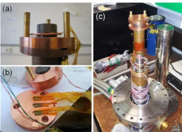
Fig. 3 (a) presents the sample stage of the cryocooler with two bulk MgB2 samples in place. There are copper discs between the 2 samples in order to connect them thermally despite the presence of the Hall probes. In Fig. 3 (b), a copper ring is fitted around the sample for better temperature exchange during the cooling, and another copper plate is then fixed above the sample containing three slits for the Hall probes. Finally, Fig. 3(c) shows the entire cryocooler head with a sample and the Hall probes in place. In this way, samples up to 4 cm in diameter and 3 cm in length can be cooled and submitted to a high magnetic field.
B. Large-sized MgB2 samples
Three large-sized MgB2 samples have been used in our trapped field measurements. The height h of each of them is 9.7 mm and they have been made using a SPS process with a heat treatment at 1 200 °C under 50 MPa pressure.
One sample, called hereafter d30, with a diameter d of 30 mm, has been reacted during 15 min. The two others samples, named d20, with a diameter of 20 mm have been reacted during 10 min each.
0 1 2 3 4 5 -1.5 -1.0 -0.5 0.0 0.5 1.0 m ( e m u ) 0H (T) 10 K 20 K 30 K
Fig. 1. Half of the Major Hysteresis Loops of the magnetic moment m of a small MgB2 sample measured at 10 K, 20 K and 30 K, for an applied field cycled between +5 T and –5 T.
0 1 2 3 4 5 102 103 104 105 106 Jc ( A /c m 2 ) 0H (T) 10 K 20 K 30 K
Fig. 2. Field dependence of the critical current density calculated at 10 K, 20 K and 30 K from the MHL in Fig. 1.
Fig. 3. (a) Head of the cryocooler with two bulk MgB2 samples in place. (b) Copper top-plate with slits for three Hall probes spaced by 1 cm. (c) The entire cryocooler system with a mounted sample.
IV. TRAPPED FIELD MEASUREMENTS
In the following, we present the trapped field measurements on the large-sized bulk MgB2 samples.
A. Field-cooling process
To activate/energize the MgB2 pellets, we employ the Field-Cooling (FC) process. For this purpose, we tried also the use of different field sweep rates in order to see the dependence on potential flux jumps of this sweep rate. An example of FC process on the sample d30 is illustrated in Fig. 4. Here, a magnetic field of 4 T is applied to the sample which is then cooled down below its critical temperature. The applied magnetic field is then decreased with a fixed sweep rate. The difference between the measured field Bmeas and the applied field Bapp is defined as the trapped magnetic field Btrap, this is the reaction of the sample. This definition of Btrap also corresponds to the magnetic polarization of the HTS sample
µ0M. The remanent trapped magnetic field Brem is defined when the applied field is zero. The definition of the trapped magnetic field Btrap is essential, since only the remanent trapped magnetic field is usually reported. However for practical applications as in [8]–[10], higher values of Btrap are of great importance. Indeed, for some kinds of high power density superconducting motors, the output power is directly dependent on the magnetic flux density that can produce HTS bulks. For example, if some HTS bulks, cooled under a field of 3 T and then submitted to a negative field of 3 T, can maintain the initial value of 3 T, this means that they can generate 6 T thanks to the current density induced inside.. This is relevant value for such applications.
B. One single MgB2 sample
In this section, we report the performances in terms of trapped magnetic field of one single MgB2 sample.
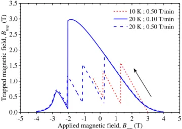
Fig. 5 shows the magnetic field trapped at the center of the surface of the sample d30 at 10 K and 20 K. At 20 K, there are less flux jumps when the field sweep rate is 0.10 T/min instead of 0.50 T/min. This sweep rate influence on the flux jumps has also been observed in [11]. The remanent magnetic
field is equal to 2.05 T at 20 K and the highest value of trapped/produced magnetic field by this sample is around 2.98 T at 20 K. Similar values around 2 T have been recently summarized for the same sample size and at the same temperature in Table 1 of [12].
Given that many flux jumps occurred at 10 K, even at low sweep rate, it was not possible to perform high trapped field at this temperature. More details concerning the flux jumps in MgB2 can be found in [13].
C. Two MgB2 samples stacked together
In this section, we report the performances in terms of trapped magnetic field of two MgB2 samples stacked together. Because we did not have two samples of 30 mm of diameter, we used samples of same properties but with a diameter of 20 mm, that is the two d20 samples. The two d20 pellets are separated by an air gap of the size of the Hall probe, i.e. 1 mm. By neglecting this air gap, it can be considered that the stack forms a single MgB2 pellet of 20 mm of diameter and roughly 20 mm height, that will be later called d20x2.
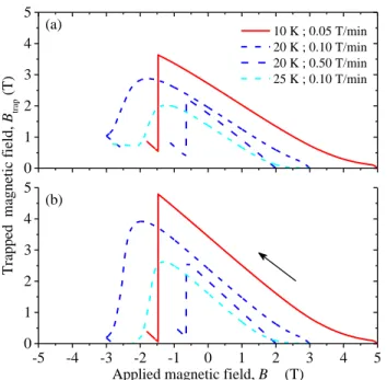
Fig. 6 shows the trapped magnetic field results on a stack of two MgB2 samples d20x2 at 10 K, 20 K and 25 K (a) at the center of the surface of the stack, and (b) at the center between the two samples. As expected, the values shown in (b) are higher than the one in (a), but the shape of the curves is the same. Some flux jumps appears at 20 K with 0.50 T/min and 10 K with 0.05 T/min. Unfortunately, it was not possible to repeat measurements at 10 K with lower sweep rates in order to remove the flux jump.
Fig. 7 shows a bar graph synthetising the results of maximum trapped magnetic field using d20x2. The red bars (left) correspond to the measures at the center of the top surface of the d20x2 assembly, whereas the black ones (right) correspond to the measures inside d20x2, in the air gap. The corresponding values are directly written above the bars. The hashed part of the bars represents the remanent trapped magnetic field Brem, when the applied field is zero, whereas the full bars are associated to the maximum trapped field Btrap achieved in our experiments. Similar results on others samples have been reported in [14], [15]. From Fig. 1 of [14], we can
0 10 20 30 40 50 60 -1.5 -1.0 -0.5 0.0 0.5 1.0 1.5 2.0 2.5 3.0 3.5 4.0 Time, t (min)
Magnetic flux density,
B
(T)
Bapp Bmes
Btrap = Bmes-Bapp
Fig. 4. Illustration of a Field Cooling (FC) process at 4 T and 20 K on the sample d30. The difference between the measured field Bmeas and the applied field Bapp is defined as the trapped magnetic field Btrap.
Fig. 5. Magnetic field trapped at the center of the surface of the sample d30 at 10 K and 20 K after field cooling at 3 T or 4 T. At 20 K, there are less flux jumps when the field sweep rate is 0.10 T/min instead of 0.50 T/min.
-5 -4 -3 -2 -1 0 1 2 3 4 5 0.0 0.5 1.0 1.5 2.0 2.5 3.0 3.5 10 K ; 0.50 T/min 20 K ; 0.10 T/min 20 K ; 0.50 T/min
Applied magnetic field, Bapp (T)
Trapped magnetic field,
Btrap
deduce the maximal trapped magnetic field Btrap inside the bulk disk pair: 6.25 T, 4.66 T, and 2.21 T, at 10 K, 20 K and 30 K, and under negative supporting field of –3 T, –2.23 T and –1 T, respectively. A value of Brem equal to 2.60 T at 20 K has also been measured inside a disk pair in [15].
V. RESULTS AND DISCUSSION
It is obvious that the remanent magnetic field anywhere in the sample cannot be higher than the irreversibility field reported in Section II.B. The irreversibility field values of our samples prepared by SPS are clearly lower than those reported in [12] for samples prepared by hot-pressing of ball-milled precursor powder, where the irreversibily fields are about 7 T at 20 K and 2 T at 30 K.
According to [16]–[18], the external magnetic field necessary for full flux penetration at the center of the sample
can be written as
bulk p 0 c d , B
J R f k with
2 1 ln 1 d d d d k f k k k (2)with Jcbulk as the field-independent bulk critical current density, R the radius, d the diameter and h the height of the sample, and kd = h / d. Since Bp corresponds to the full penetration field, it gives an idea of the achievable trapped magnetic flux density at the center of the sample. However, (2) is based on the hypothesis of a constant critical current density and does not take into account the Jc(B) law of the material. Using the same hypotheses, one can also express the corresponding field at the center of the surface of the sample, see (12) in [18]:
bulk s p 0 c , 2 R B J R f k with kR2kd h R/ (3)In that case, the ratio Bp / Bps is only driven by geometric parameters. For the samples studied here, this ratio is equal to 1.51, 1.63 and 1.82 for d30, d20 and d20x2, respectively. As
lim ( ) 1
kf k , a ‘half’ infinite long cylinder would correspond to a ratio Bp / Bps of 2. However, extrapolating the value of the trapped magnetic field at the center of the sample, as some authors do, by multiplying the value of the trapped magnetic field at the surface with the theoretical ratio Bp / Bps is not sufficient, and leads to overestimated values. The comparison is made in Table I for d20x2. Given the fact that the only relevant value for the practical applications as permanent magnet is the trapped magnetic field at the surface of the sample, the value of the trapped field inside the sample is usually reported for comparison reasons or in order to impress. From (2) and (3), one can say that the trapped magnetic field, for a fixed height of the sample, can be increased simply by increasing the diameter of the sample. Theoretically, choosing d30 instead of d20 leads to 26% and 35% of increase for Bp and Bps, respectively. In the same way, choosing d20x2 instead of d20 leads to 23% and 10% of increase for Bp and
Bp s
, respectively. Therefore, the increase of the trapped magnetic field at the surface of the sample is more significant by increasing the diameter from 20 mm to 30 mm that by doubling the height of d20. Finally, choosing d30 instead of
d20x2 leads to 2% and 23% of increase for Bp and Bps, respectively. The same tendency is reported experimentally at 20 K, the increase of the maximal trapped field from d30 to
d20x2 is about 3%.
From (3), the field-independent bulk critical current density
Jc bulk
can be calculated. For d20x2 at 20 K, with 2.88 T of maximum trapped magnetic field at the surface of the sample,
Fig. 6. Trapped magnetic field results on a stack of two MgB2 samples d20x2 at 10 K, 20 K and 25 K (a) at the center of the surface of the stack, (b) at the center between the two samples.
Fig. 7. Bar graph synthetising the results of maximum trapped magnetic field using d20x2. The hashed part of the bars represents the remanent trapped magnetic field Brem, whereas the full bars are associated to the maximum trapped field Btrap.
0 1 2 3 4 5 (a) -5 -4 -3 -2 -1 0 1 2 3 4 5 0 1 2 3 4 5
Applied magnetic field, Bapp (T)
Trapped magnetic field, Btrap (T) 10 K ; 0.05 T/min 20 K ; 0.10 T/min 20 K ; 0.50 T/min 25 K ; 0.10 T/min (b) 3.63 2.88 2.24 2.03 2.72 1.95 1.37 1.75 3.63 2.88 2.24 2.03 2.72 1.95 1.37 1.75 4.80 3.92 2.65 2.63 3.44 2.40 1.61 2.01 4.80 3.92 2.65 2.63 3.44 2.40 1.61 2.01 10 K 0.05 T/min 20 K 0.10 T/min 20 K 0.50 T/min 25 K 0.10 T/min 0 1 2 3 4 5 Top Inside
Trapped magnetic field,
Btrap
(T)
TABLEI
COMPARISON OF THEORETICAL AND EXPERIMENTAL RATIO BP / BP S Ratio Bp / Bps 10 K 0.05 T/min 20 K 0.10 T/min 20 K 0.50 T/min 25 K 0.10 T/min Theoretical 1.82 1.82 1.82 1.82
With Btrapmax 1.32 1.36 1.18 1.30
Jcbulk is estimated around 48 kA/cm2. This value corresponds to the Jc(B) curve shown in Fig. 2 at 20 K and for B = 1.6 T. Therefore, the mean value of trapped magnetic field in the sample volume is approximately equal to this value of 1.6 T.
The values obtained here of the remanent trapped magnetic field measured at the center of the surface of the sample are a little bit lower than highest reported up to now in [12], i.e. 4.6 T, 3.3 T and 2 T, at 15 K, 20 K and 25 K, respectively. However, the obtained values of the maximal trapped magnetic field for d20x2 of 3.63 T at 10 K, 2.88 T at 20 K (2.98 T for d30) and 2.03 T at 25 K are really interesting for the intended applications.
VI. CONCLUSION
The trapped magnetic field, not only at the surface of a sample produced by SPS, but also inside a stack of two MgB2 samples, has been deeply investigated. The useful values of trapped magnetic field obtained at 20 K at the surface of the samples are really interesting for the intended applications. According to these values, to their very low density compared to other materials and to their ease of manufacturing, MgB2 bulks are promising materials for the applications of superconductors.
ACKNOWLEDGMENT
The authors would like to thank T. Karwoth and X. Zeng for their help during trapped field measurements at Saarland University.
REFERENCES
[1] J. Nagamatsu, N. Nakagawa, T. Muranaka, Y. Zenitani, and J. Akimitsu, “Superconductivity at 39 K in magnesium diboride,” Nature, vol. 410, no. 6824, pp. 63–64, Mar. 2001.
[2] M. Muralidhar, Y. Fukumoto, A. Ishihara, K. Suzuki, M. Tomita, M. R. Koblischka, A. Yamamoto, and K. Kishio, “Recent developments in melt processed Gd-123 and MgB2 materials at RTRI,” Phys. C
Supercond., vol. 496, pp. 5–10, Jan. 2014.
[3] T. Prikhna, W. Gawalek, M. Eisterer, H. W. Weber, M. Monastyrov, V. Sokolovsky, J. Noudem, V. Moshchil, M. Karpets, V. Kovylaev, A. Borimskiy, V. Tkach, A. Kozyrev, R. Kuznietsov, J. Dellith, C. Shmidt, D. Litzkendorf, F. Karau, U. Dittrich, and M. Tomsic, “The effect of high-pressure synthesis on flux pinning in MgB2-based superconductors,” Phys. C Supercond., vol. 479, pp. 111–114, Sep. 2012.
[4] J. G. Noudem, M. Aburras, P. Bernstein, X. Chaud, M. Muralidhar, and M. Murakami, “Development in processing of MgB2 cryo-magnet superconductors,” J. Appl. Phys., vol. 116, no. 16, p. 163916, Oct. 2014. [5] D.-X. Chen and R. B. Goldfarb, “Kim model for magnetization of type II superconductors,” J. Appl. Phys., vol. 66, no. 6, pp. 2489–2500, Sep. 1989.
[6] A. Sanchez and C. Navau, “Critical-current density from magnetization loops of finite high-Tc superconductors,” Supercond. Sci. Technol., vol. 14, no. 7, pp. 444–447, Jul. 2001.
[7] D. Batalu, G. Aldica, S. Popa, L. Miu, M. Enculescu, R. F. Negrea, I. Pasuk, and P. Badica, “High magnetic field enhancement of the critical current density by Ge, GeO2 and Ge2C6H10O7 additions to MgB2,” Scr.
Mater., vol. 82, pp. 61–64, Jul. 2014.
[8] P. Masson, J. Leveque, D. Netter, and A. Rezzoug, “Experimental study of a new kind of superconducting inductor,” Appl. Supercond. IEEE
Trans. On, vol. 13, no. 2, pp. 2239–2242, 2003.
[9] D. Netter, J. Leveque, E. Ailam, B. Douine, A. Rezzoug, and P. J. Masson, “Theoretical study of a new kind HTS motor,” Appl.
Supercond. IEEE Trans. On, vol. 15, no. 2, pp. 2186–2189, 2005.
[10] P. J. Masson and C. A. Luongo, “High power density superconducting motor for all-electric aircraft propulsion,” Appl. Supercond. IEEE
Trans. On, vol. 15, no. 2, pp. 2226–2229, 2005.
[11] G. Aldica, M. Burdusel, and P. Badica, “Trapped magnetic field in a (NdFeB)–(MgB2) pair-type bulk magnet,” Phys. C Supercond., vol. 505, pp. 18–23, Oct. 2014.
[12] G. Fuchs, W. Häßler, K. Nenkov, J. Scheiter, O. Perner, A. Handstein, T. Kanai, L. Schultz, and B. Holzapfel, “High trapped fields in bulk MgB2 prepared by hot-pressing of ball-milled precursor powder,”
Supercond. Sci. Technol., vol. 26, no. 12, p. 122002, Dec. 2013.
[13] V. Chabanenko, R. Puźniak, A. Nabiałek, S. Vasiliev, V. Rusakov, L. Huanqian, R. Szymczak, H. Szymczak, J. Jun, J. Karpiński, and V. Finkel, “Flux Jumps and H-T Diagram of Instability for MgB2,” J. Low
Temp. Phys., vol. 130, no. 3–4, pp. 175–191, Feb. 2003.
[14] A. Yamamoto, A. Ishihara, M. Tomita, and K. Kishio, “Permanent magnet with MgB2 bulk superconductor,” Appl. Phys. Lett., vol. 105, no. 3, p. 032601, Jul. 2014.
[15] J. H. Durrell, C. E. J. Dancer, A. Dennis, Y. Shi, Z. Xu, A. M. Campbell, N. H. Babu, R. I. Todd, C. R. M. Grovenor, and D. A. Cardwell, “A trapped field of >3 T in bulk MgB2 fabricated by uniaxial hot pressing,” Supercond. Sci. Technol., vol. 25, no. 11, p. 112002, Nov. 2012.
[16] B. Douine, C.-H. Bonnard, F. Sirois, K. Berger, A. Kameni, and J. Leveque, “Determination of and -Value of HTS Pellets by Measurement and Simulation of Magnetic Field Penetration,” IEEE Trans. Appl.
Supercond., vol. 25, no. 4, pp. 1–8, Aug. 2015.
[17] E. H. Brandt, “Superconductor disks and cylinders in an axial magnetic field. I. Flux penetration and magnetization curves,” Phys. Rev. B, vol. 58, no. 10, pp. 6506–6522, Sep. 1998.
[18] A. Forkl, “Magnetic flux distribution in single crystalline, ceramic and thin film high-Tc-superconductors,” Phys. Scr., vol. 1993, no. T49A, p. 148, Jan. 1993.