Computational Bounce Flash for Indoor Portraits
byLukas Murmann
M.Sc. Computer Graphics, Vision and Imaging University College London, 2013
B.Sc. Electrical Engineering Technische Universitit Mdrnchen, 2012
MASAHUSETS INSTITUTEOF TECHNOLOGY
JUN 2 3
017
LIBRARIES
'ARCHIVES
SUBMITTED TO THE DEPARTMENT OF ELECTRICAL ENGINEERING AND COMPUTER
SCIENCE IN PARTIAL FULFILLMENT OF THE REQUIREMENTS FOR THE DEGREE OF MASTER OF SCIENCE IN
COMPUTER SCIENCE AND ELECTRICAL ENGINEERING AT THE MASSACHUSETTS INSTITUTE OF TECHNOLOGY
JUNE 2017
2017 Massachusetts Institute of Technology. All rights reserved.
Signature of Author:
Signature redacted
Department of Electrical Engineering and Computer Science, May 19, 2017
Signature redacted
Certified by:Fredo Durand Professor, Department of Electrical Engineering and Computer Science Thesis Supervisor
Accepted by:
Signature redacted
/
Mr~sor Leslie A. Kolodziejski Chair, Committee for Graduate StudentsComputational Bounce Flash for Indoor Portraits
by
Lukas Murmann
Submitted to the Department of Electrical Engineering and Computer Science on May 19, 2017, in partial fulfillment of the requirements for the degree of
Master of Science in Computer Science and Electrical Engineering
Abstract
Portraits taken with direct flash look harsh and unflattering because the light source comes from a small set of angles very close to the camera. Advanced photographers address this problem by using bounce flash, a technique where the flash is directed towards other surfaces in the room, creating a larger, virtual light source that can be cast from different directions to provide better shading variation for 3D modeling. However, finding the right direction to point a bounce flash towards requires skill and careful consideration of the available surfaces and subject configuration. Inspired by the impact of automation for exposure, focus and flash metering, we automate control of the flash direction for bounce illumination. We first identify criteria for evaluating flash directions, based on established photography literature, and relate these criteria to the color and geometry of a scene. We augment a camera with ser-vomotors to rotate the flash head, and additional sensors (a fisheye and 3D sensors) to gather information about potential bounce surfaces. We present a simple numer-ical optimization criterion that finds directions for the flash that consistently yield compelling illumination and demonstrate the effectiveness of our various criteria in common photographic configurations.
Thesis Supervisor: Fr6do Durand
Acknowledgments
I would like to thank my advisor Fr6do Durand for his support and guidance, for first showing me how to take good photographs, and then showing me how to make computers take good photographs, too. I also would like to thank Jan Kautz, who as my advisor at UCL introduced me to the wonderful world of computer graphics, and who I was fortunate to again collaborate with on the bounce flash project.
Thanks to Abe Davis who was an incredible collaborator and who taught me much about doing research. I want to thank everyone in the MIT computer graphics group, especially my office mates Zoya Bylinskii, Alexandre Kaspar, and Tzu-Mao Li.
I am grateful to everyone who modelled for this work, who remained patient while I was busy ironing out unexpected quirks of the camera prototype.
Contents
1 Introduction
2 Related Work
2.1 Flash and M etering . . . . 2.2 Computational Illumination . . . . 2.3 Guidelines for Bounce Flash . . . .
3 The Computational Bounce Flash System
3.1 Bounce Flash Objective . . . . 3.2 Hardware Prototype . . . .
4 Results
4.1 Standard Flash Directions . . . . 4.2 User Study . . . . 4.3 Effect of Geometry, Reflectance, and Gaze . . 4.4 Dynamic Environments . . . . 4.5 Additional Applications . . . . 4.6 Discussion of Results . . . . 5 Conclusion
A Geometry Reconstruction and Pose Tracking
5 7 7 8 9 13 13 16 18 . . . . 18 . . . . 20 . . . . 21 . . . . 22 . . . . 24 . . . . 26 28 29
Chapter 1
Introduction
It is well known among photographers that direct camera flash leads to unflatter-ing images - putting such a small light source so close to the camera prevents soft shadowing, making subjects appear flat and harsh
16,
22, 11, 29, 30]. Advanced pho-tographers avoid this by using a bounce flash to reflect light off other surfaces around their subject, thereby creating a much larger virtual light source that can be cast from better directions. Effective use of a bounce flash is difficult though; the photographer must dynamically predict how light will interact with a complex 3D environment, considering factors like the color and albedo of a bounce surface, its position and an-gle relative to the flash and subject, as well as whether the resulting light will create unpleasant shadows. Even savvy photographers often have trouble using a bounce flash. For example, one common mistake is to use the ceiling between the camera and a human subject as a bounce surface[6,
22]. This unfortunately causes the subject's brow to cast shadows into the eyes, resulting in what is known as "raccoon eyes"130].
Most photography occurs in dynamic situations where both the photographer and subject move through the scene, challenging even seasoned photographers to con-stantly evaluate and manually adjust the direction of their flash to adapt to the new arrangements of camera, subject, and scene. This is so challenging that it is common practice for professional wedding photographers to scout location before an event and test out potential bounce surfaces[301.
through-the-lens flash metering
1131,
we propose an automatic solution for controlling the direction of a bounce flash. We augment a regular camera with additional sensors to evaluate the color and geometry of a scene, and automatically direct an actuated, camera-mounted flash toward good bounce surfaces. For amateur photographers this provides a way to reap the benefits of a well-placed bounce flash without having to understand the principles behind its use. For professionals, we provide a convenient and effective default option for when the photographer wants to focus their attention on other aspects of a shot.Lighting for photography is a deep topic, and different photographic styles call for different lighting strategies in different situations. We focus primarily on indoor portraiture, the most common use case for bounce flash, and design an objective for evaluating flash directions based on documented principles and rules of thumb from established literature on photography. While the 'best' flash direction in a scene may be a matter of taste, there is often consensus on directions that should be considered 'bad'. Our objective is designed to prioritize avoiding these 'bad' directions and maximize the chances that the user will capture a useful image.
This work makes the following contributions:
e We present the first solution to automatic bounce flash, using servos to actuate the flash and additional sensors to gather information about the environment. e We present heuristic criteria to optimize the direction of the bounce flash and
in particular maximize the size of the virtual light source, its direction, and avoid color casts. We demonstrate that factors such as scene reflectance, 3D geometry, and subject head direction are critical.
e We evaluate our system's results in a user study, and explore additional uses in object and panorama photography.
Chapter 2
Related Work
Our solution for automatic bounce flash [19] is inspired by photographic assistants such as automatic metering or auto focus. These assistants make photography more accessible to novices, and more convenient for professionals. The first section in this chapter will provide an overview over these techniques. A number of works from the computer graphics community use computer-controlled illumination to improve the
lighting of photographs. We will introduce these techniques in Section 2.2. Finally, the
photography literature offers detailed discussions of techniques for portrait lighting. In Section 2.3, we synthesize the advice provided in the literature, and discuss how these photography best practices influence the design of an automatic solution for bounce flash.
2.1
Flash and Metering
On-Camera Metering Our work is inspired by on-camera metering for exposure, focus, and white balance, which started to appear on cameras in the second half of the
twentieth century, e.g., 113]. Earlier cameras offered only manual controls. and the
introduction of on-camera metering led to metering "modes," which optimized some
subset of the camera's parameters according to the current sensor readings. Aperture priority mode, for example, let the user fix the aperture size and automatically ad-justed shutter speed and ISO according sensor readings. Today, most cameras offer
a variety of modes in addition fully automatic metering. Offering several options addresses the fact that there is no one-size-fits-all solution to metering; the "right" settings may be different for different photographers with different goals.
TTL Flash Metering Metering for flash is more difficult than for exposure or focus because the camera has no way to predict the effect of a flash until it is fired. Modern flash metering is called through the lens (TTL) metering and derives from OTF (Off-The-Film) metering introduced by Olympus in the seventies [13]. It uses a combination of a pre-flash and tight feedback to stop the flash when an image has reached a specified level of exposure. TTL metering is complementary to our work since it only controls the quantity of light, while we aim to control the quality of light, and in particular its size and direction.
2.2
Computational Illumination
Computational illumination is an area of computational photography that seeks to computationally control and exploit illumination. Like our work, several papers have focused specifically on addressing problems associated with direct flash. However, previous approaches have accomplished this by combining multiple exposures, typi-cally taken with and without a direct flash
[24,
9, 2j. More recent approaches avoid firing a visible flash directly at portraiture subjects by instead using near-infrared or UV flashes [15, 32]. Adelsberger et al. [1] replace the flash with a video projector to finely control the spatial light distribution, but still in a configuration where illu-mination comes from the camera direction. Like us, they use 3D sensing to adapt the illumination to the scene. Raskar et al. [25] use multiple flashes to extract scene edges and create non-photorealistic renditions. In contrast to these approaches, our work focuses on automating the existing, single-exposure solution preferred bypho-tographers - a bounce flash.
Other approaches rely on additional light sources that are not attached to the camera. For example, the light stages of Debevec et al. capture spherical basis
func-tions, e.g.
[8]
that can be used to computationally relight subjects after the fact. Mohan et al.[18]
seek to achieve similar results with a tabletop configuration, and Malzbender et al.1171
capture relightable textures from multiple viewpoints. De Decker et al. [71 and Fyffe et al. [10] added color multiplexing for efficient cap-ture. Boyadzhiev et al.14]
focus on organizing and recombining photos taken of a static scene under different illuminations. Srikanth et al.[26]
mount a light source on UAV, which they direct to achieve rim lighting of a subject. These systems achieve impressive results, but lack the convenience of an on-camera solution. In contrast, we provide a solution that simply augments a form factor photographers are already comfortable with.The flash has also been used to extract additional information such as alpha mattes
[27,
28]. Projector-camera setups can be used to separate different illumination components, e.g., [201, increase depth separation[161
and create photographic effects such as highlighted depth of field [14]. Tight synchronization between a projector and the camera readout can further increase the light efficiency of computational illumination [23].Photography lighting can also be modified as a post-process using a variety of relighting techniques, e.g. [31, 21], but they can be more involved and robustness is not guaranteed. In contrast, we want to achieve good lighting in camera by controlling the flash.
2.3
Guidelines for Bounce Flash
In photography, light is usually characterized by three qualities 112, 29]:
1. Size: a large light source that casts light from many angles will create softer
shadows and highlights than a small point light source,
2. Direction: the angle of a light source determines where shadows are cast, and how large they are, and
Size and direction are the main challenges for flash photography. Direct flash is by nature too small, which yields harsh shadows and highlights. It also comes from the same location as the camera, casting few shadows that could indicate shape. Bounce flash addresses these shortcomings by using indirect illumination to create a larger virtual light source away from the camera. Effective use of the bounce flash amounts to predicting the size, direction and color of this virtual light source. We take each of these factors in turn and examine what aspects of the shooting configuration affect them. This discussion informs the sensors we attach to our camera, and how we can define an objective that turns photographic guidelines into numerical criteria.
Size: The virtual size of the light source as seen from the subject depends on the field of view of the flash and the relative geometry of flash, reflector, and subject. Our prototype uses a flash with a fixed field of view, though flash zoom would be simple to add as a variable to our optimization. The relative distance and orientation of the reflector with respect to the flash and subject then determine the virtual light size. For example, when the flash is projected towards a wall that is very close, the resulting light is small. This criterion requires knowledge of the 3D environment, which is why we augment the camera with 3D sensors. Given 3D data, we use a simple computer graphics simulation to estimate the size of the virtual light source. Figure 2-1 visualizes the virtual light source size when using bounce flash.
light source angular extent 0
Figure 2-1: Left: When using direct flash, the subject is illuminated by only a tiny light source which leads to hard shadows. Right: With bounce flash, the angular extent of incident illumination is larger which softens shadows. The goal of our system is to maximize the size of the virtual light source.
Direction: Light direction tends to offer the most creative freedom, with a variety of strategies leading to different portrait styles. In the spirit of automation, we seek a solution that most users will find pleasing based on established guidelines outlined in photography textbooks (e.g. [11, 29, 30]). First, most texts agree that the eyes are the focal point of portrait photography and, with the exception of a few styles (such
as film noir), they urge photographers to make sure the eye sockets are well lit. This is why the naive bounce flash approach of directing the flash towards the ceiling is usually ill-advised; it causes the eyebrows to cast a shadow in the eye sockets. Instead, light should ideally come from just slightly above eye level, since most natural light is above the horizon (see Fig 2-2).
Figure 2-2: Left: Placing the light source directly above the subject leads to unwanted shadows on the subject's face. Right: It is better to place the virtual light source in front of the subject, slightly above eye level.
When the head is turned to a side, lighting can then be classified into two main strategies: "broad lighting", where light comes from the side facing the camera, and "short lighting," where light is cast from the direction the subject is facing. As broad lighting is known to offer weaker shape perception of the face [11, 29, 30], we focus on the more common "short lighting" style. In summary, we preferentially choose flash directions that result in the commonly accepted style of lighting that places the light slightly above eye level (but not too much), and has a slight bias to the side of a subject's gaze. This bias requires knowledge of face pose, which we obtain with a face and gaze detector [3].
Color: Finally, photographers are advised to avoid excessively colorful bounce sur-faces that may yield an unpleasant color cast. This criterion is the simplest to un-derstand and implement: our flash should prefer white and gray surfaces to highly saturated ones (see Fig 2-3).
Non-N.utraI Rdf or Non-Neutral Reflector
Figure 2-3: Left: Light that bounces off a colorful surface leads to unpleasant color cast. Right: Photographers avoid colorful surfaces and point the flash towards neu-tral (white or gray) surfaces instead.
Our task is to define and evaluate an objective for controlling the flash direction based on the above principles. For this we need to capture information about the color and geometry of the scene. We do this by augmenting our camera with additional sensors, namely a fish eye camera and 3D sensors. Our objective is evaluated on the data provided by these sensors, and used to computationally control a motor-actuated electronic flash head mounted on our camera.
Chapter 3
The Computational Bounce Flash
System
3.1
Bounce Flash Objective
As the photographer moves through the scene, our system continually captures the color and geometry of the scene as well as the subject gaze and evaluates potential flash directions. For each candidate flash direction 'flash, we use simple single-bounce computer graphics to evaluate light at the subject location and compute a score
S(a('flash). Every frame, the system finds the flash direction (flash that maximizes the
score S:
tbflash = arg max S(Iflah) (3.1)
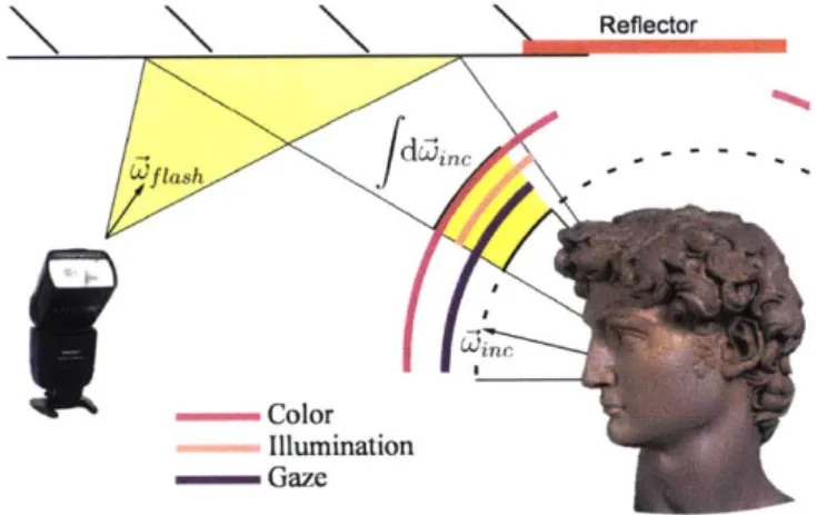
As previously outlined, S should favor directions that lead to a bounce flash with large virtual light source, coming from the right direction, and having neutral color. For each candidate flash direction 'flash, we project the flash frustum onto our ac-quired geometry to create a virtual bounce light source and rasterize it into an en-vironment map from the viewpoint of the subject, using shadow maps to handle visibility. Then, for each environment map direction 'c, we score its contribution and take the integral: (Note that 'ine is a direction with respect to the subject, while
(c)=
f
Illumination(oflah, inc) Gaze(4nc) - Color(ine) dai5e (3.2)winc
The three factors inside the integral are binary functions. Illumination() measures whether a point on the bounce surface is illuminated by the flash. To achieve a high objective score, Illumination() must cover a large area of solid angle, which fulfills the first criterion in Section 2.3. Gazeo favors points in the direction where the subject is looking. See Figure 3-1 for a visualization of the three binary functions.
Reflector
Wf lash Wn
-- Color Illumination
- Gaze
Figure 3-1: Shown are the candidate flash direction &'flsh, the thee binary functions, and the effective angular light source extent f dbi. Only samples where all three binary functions evaluate to 1 (highlighted in yellow) contribute to the overall score for this candidate direction.
The goal of this function is to achieve good modeling while avoiding distracting shadows (second criterion in Section 2.3). It is non-zero only for points within a vertical range from horizontal to 40 degrees up to avoid eye shadows, and extends horizontally by 60 degrees in both directions from the estimated gaze angle. ColorO measures the color saturation of the bounce surface and penalizes excessively colorful points (third criterion in Section 2.3). The function is implemented as a threshold on wall color saturation, where saturation is calculated from the RGB color channels
as sat = (maxrgb - minrgb) / (maxrgb + eps). We typically set the saturation
Wflash uniformly over the hemisphere. The objective function S(W'flash) is evaluated by integrating over a cube map rendered from the position of the subject, where win indicates a direction through a texel in the cube map. The system computes the maximizer 6flash at interactive frame rates (10 frames per second on a laptop computer), allowing the prototype to adjust dynamically to changes in subject pose
and scene.
Analysis of IlluminationO, GazeO, and Color() Factors Figure 3-2 shows an example of the factors in the objective function. The results were taken in a mostly white room with reflecting walls to the left, right, and top of the subject. The scene contains ample neutral-colored reflectors. Thus, the subject's gaze direction becones the deciding factor in determining the light source placement.
YU
Gaze Right Gaze Left
Figure 3-2: Shown in the center of the top row are the fisheye image and the ColorO factor. Since the room contains many white walls, the color factor is set to 1 for most directions over the hemisphere. The top-left figure shows the Gaze() factor when the subject looks to the right of the camera. In this case, directions to the back and to the right of the camera correspond to surface points in front of the subject. The flash direction that maximizes the objective function is upwards and to the right (enter row, left). Shown on the right are the Gaze() and IlluminationO factors when the subject looks to the left of the camera. The flash direction that maximizes the overlap of the three factors points to the left, up, and slightly behind the camera.
In the example on the left of Fig 3-2, the subject looks to the right of the camera. As a result, surface points to the right and back of the camera are considered to be in
Flash head and servo motors
Depth Sensors
Fisheye Camera
Main Camera
Figure 3-3: System overview: Fisheye camera and depth sensors capture data about the camera's environment. From the main camera feed, we extract the subject's gaze direction. A laptop computer finds the optimal flash direction and updates the pose of the motor-controlled flash head.
front of the subject, and contribute to the objective function when illuminated. The optimization procedure now searches the space of flash directions for biggest neutral-colored virtual light source in front of the subject. In this case, pointing the flash to the right and up maximizes the objective function (left heatmap) and results in the picture shown in the bottom left.
We now consider the case where the subject is looking to the left of the camera. The set of surface points considered to be in front of the subject changes (Fig 3-2 top-right). The light source placement from the previous case now barely illuminates surface points in front of the subject. Running the optimization procedure again yields a flash direction to the left, up and back. This direction again maximizes the objective function (right heatmap).
3.2
Hardware Prototype
We constructed a prototype based on a Sony a6000 mirrorless camera and a Sony
HVL-F
43M
flash (Figure 3-3). The flash head was split from the heavier battery pack and mounted on a two degrees of freedom pan-tilt bracket actuated by twobased microcontroller board. Our prototype uses a laptop for computation, but an optimized implementation could perform this computation on the device itself.
The hardware prototype is largely assembled from off-the-shelf parts. These in-clude camera cage, pan-tilt bracket for flash, servo motors, and support structures. Overall, assembly of the prototype does not require advanced knowledge of hard-ware design or fabrication. To facilitate reproducibility, we include a list of parts in the supplementary material. Further, the supplementary material contains high-level assembly instructions and schematics for custom parts like the sensor mount.
Geometry Acquisition Our system reconstructs the scene's geometry using four
Intel Realsense R200 active stereo sensors, with a FOV of 56 by 43 degrees. The
sensors are aligned to capture a wide field-of-view to the top, side, and back of the photographer. This particular arrangement leaves gaps between the four sensors, and more sensors would be needed to capture a complete hemisphere or more. This would make our prototype unwieldy, and instead we fill in the system's blind spots by extrapolating the acquired geometry. More details can be found in the appendix. We anticipate spherical or hemispherical depth sensors appearing in the future (driven by the increasing popularity of VR), which will significantly simplify omnidirectional geometry acquisition.
Scene Reflectance In order to determine an appropriate flash direction, we also take the reflectance of the surrounding surfaces into account. Since we only consider flash directions in the upper hemisphere to be relevant for bounce-flash photography, we only need to acquire color images of the upper hemisphere. To this end, we use a
1800 fisheye lens mounted on a Pointgrey FL3-U3-88S2C-C USB3 camera.
Gaze Direction For gaze detection, we capture the camera's viewfinder feed via HDMI. From the captured video frames, we estimate subject position and orientation relative to the camera using the Cambridge Face Tracker library [3].
Chapter 4
Results
The goal of our system is to consistently and automatically provide good indirect illumination. We evaluate this in several ways. First, we have captured various combinations of subjects, scenes, and poses, using the bounce direction chosen by our optimization, as well as standard recommended flash directions for comparison (see Fig. 4-2). We provide several of these examples for visual comparison, and also evaluate them in a user study. We also show how our system responds dynamically to changes in a scene. We provide results captured before and after changes in the reflectance, geometry, and gaze direction of a scene. In our supplemental video, we show our system responding in realtime to changing scenes, including one sequence where the system itself moves backwards down a hallway with a walking subject. Finally, we discuss secondary use cases for our system, including object photography and surface tracking for handheld panorama capture.
4.1
Standard Flash Directions
Photography textbooks often introduce the bounce flash by recommending some standard directions to point the flash (e.g., [6, 22]). Photographers are taught the strengths and weaknesses of each standard direction, then encouraged to choose the one that best fits their subject and scene. To evaluate our objective function, we compare images taken using the flash direction chosen by our optimization to some
of these commonly recommended, standard directions. Fig. 4-1 shows the standard directions used for comparison. We captured the standard directions automatically with our system by programmatically moving the flash to each standard direction after capturing the one chosen by our optimization.
Left Right
Front Back
Figure 4-1: The standard bounce flash directions we compare against: In the top, the flash is held on eye level, and rotated 450 to the left and right respectively. These directions are meant to achieve short lighting, but often fail depending the environment and subject gaze. On the bottom left, the flash is positioned 45' upwards, towards the ceiling. This often produces a neutrally-colored virtual light source, but tends to case unwanted eye shadows. On the bottom right, the flash is positioned 450 upwards behind the photographer. This tends to create a large light source, but casts from an unideal direction and often places the light too far away resulting in underexposure.
The flash direction chosen by our system is often close to one of the standard directions. Intuitively, this makes sense, as the standard directions were chosen based on many of the same principles that guide our objective function. However, a given standard direction is not always optimal, and each standard direction has its own fail-ure cases. Our goal is not to always do better than all of the standard directions, but rather to provide an automatic solution that does at least comparably well, avoiding failure cases, making bounce flash accessible to novice users, and freeing advanced users to focus on other aspects of photography.
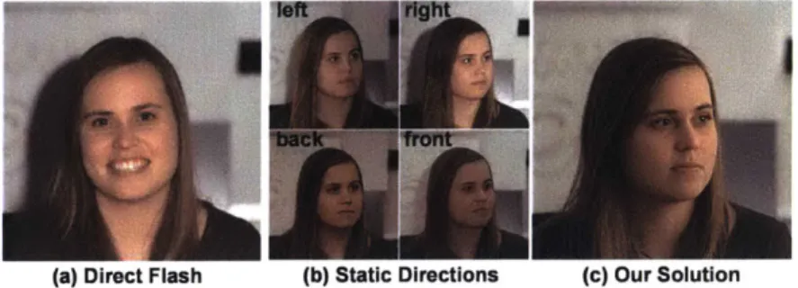
(a) Direct FIasn () tatic uirections (C) uur boution
Figure 4-2: Direct flash produces harsh illumination. Static flash directions work in some configurations, but do not adjust to subject pose, surface reflectance, or scene geometry. Our prototype takes these factors into account, which leads to consistently good illumination.
Figure 4-3: Our optimized flash direction produces compelling results, which match or exceed the quality of default directions recommended by photography texts.
4.2
User Study
We conducted an online survey to evaluate the performance of our algorithm com-pared to the directions shown in Fig. 4-3. The survey is based on 14 indoor portraiture configurations, where each configuration is photographed using five different flash di-rections: {OURS, FRONT, BACK, LEFT, RIGHT}.
We presented each survey participant with all 14 configurations. For each config-uration, we presented the participant with a full pairwise comparison (10 pairs). The order of the configurations and the order of the pairings were randomized. Partici-pants were asked to chose their preference for all pairs, yielding 140 data points per participant. We recruited 20 participants for our survey using Amazon Mechanical Turk1; 18 of the 20 participants submitted valid questionnaires.
The scores from these pairwise comparisons are reported in Fig. 4-4. We test the statistical significance of our results according to the ANOVA framework. The ANOVA confirms that the choice of flash direction leads to significant differences in mean scores at p = 1%. We further conducted Least Significant Difference tests on the scores reported in Fig. 4-4: With a 1% p-value, OURS has a significantly higher mean score than any of the other directions.
number of wins in pairwise comparisons 40 N=1 8 participants p=1 % 35 30 25 20 15 10 5 0
OURS FRONT BACK LEFT RIGHT
Figure 4-4: Each survey participant chose a preference in 140 pairwise comparisons. Based on a total 2520 individual votes from 18 survey participants, OURS achieves the highest mean number of wins.
4.3
Effect of Geometry, Reflectance, and Gaze
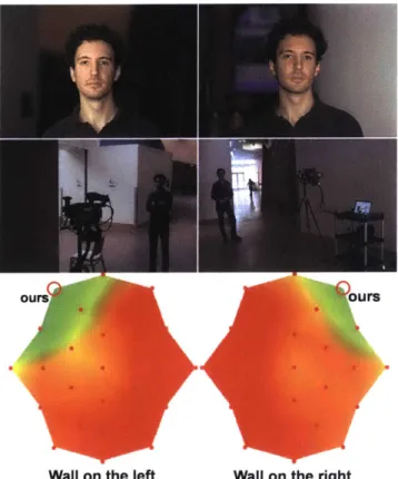
We now look at heat maps representing our energy function in Eq. 3.1 and see how they are affected by reflectance, geometry, and head direction. These visualizations show a color mapping of our objective S over the space of possible hemispherical flash directions, where green is best and red is poor. Fig. 4-5 illustrates a scene where geometry severely limits options. Most scene surfaces are too distant to yield a good bounce flash, and only a nearby wall is viable. Fig. 4-6 and 4-7 illustrate how scene reflectance can yield undesirable color casts and how the color term in Eq. 3.1 drives the optimization away from such surfaces. Fig. 4-8 demonstrates the impact of face orientation. When this criterion is ignored, the light may come from the direction opposite the subject's gaze and illuminate only the side of the face closest
Wall on the left Wall on the right
Figure 4-5: In this scene with high ceilings, only a single wall is viable as a bounce surface. In the bottom row, we see the objective function. When we change the direction of the shot, the objective function adapts to the new environment.
to the camera. This is often called "broad lighting" and it does not provide good modeling of the face, and it can lead to unpleasant shadows on the other side [29, 30].
In contrast, our approach takes the head orientation into account biasing our flash direction towards a more pleasant "short lighting" look.
4.4
Dynamic Environments
Bounce flash is especially difficult to use in dynamic environments, and yet scenarios that involve a moving camera and subject are very common in photography. Our supplemental video shows our system being used in one such scenario, leading a walking subject down a long corridor. Effective use of a normal bounce flash would be extremely difficult in this scenario, even for expert photographers, as it would involve constantly analyzing the changing surroundings, adjusting the flash, and keeping the
With 6urtain No curtain
Figure 4-6: The effect of changing the scene reflectance. On the left, the flash is avoiding the brightly colored curtain, firing at the ceiling instead. On the right, the curtain is pulled back, revealing a white surface. Additional material can be found in the supplementary video.
Reflectance considered Reflectance ignored
Figure 4-7: In this result, there is a brightly colored curtain to the front-right of the camera (see Figure 4-6 and supplementary video). In the left, our solution pointed the flash at the ceiling, leading to an image with natural color temperature. On the right, we ignored the measured surface reflectance, assuming white reflectors instead. Ignoring surface reflectance, the system pointed the flash to the bright curtain, which leads to a strong color-cast in the captured image.
camera centered, all while walking backwards in pace with the subject. Fig. 4-9 shows two of the images captured in this sequence, as well as two screen shots from the accompanying video that illustrate decisions made by our system. This example is best appreciated in the accompanying video.
Gaze direction considered Gaze ignored
ours
Gaze Left Gaze Frontal Gaze Right
Figure 4-8: Shown in the bottom are the objective functions of the subject looking to the left, straight into the camera, and to the right respectively. Since the photos are captured in a mostly symmetrical room, the effect of the gaze tracker is isolated. On the top, we show the detrimental effect of ignoring the gaze tracker, and always assuming frontal gaze instead.
4.5
Additional Applications
Object Photography Photographing objects, in particular shiny objects, can be a surprisingly difficult task for novice photographers. Under ambient illumination, the object appears too dark, and is missing the specular highlights that signal its glossy appearance. Adding small light sources like room lights or direct flash introduces very narrow highlights, that don't fully convey the object's shape. A good light setup uses large light sources to model the object's highlights [121. However, these light configurations are out of reach for casual photographers.
Fig. 4-10 shows how our prototype can be used to capture compelling images of glossy objects, without expensive lighting equipment. For object photography, we disable the gaze detector, and instead instruct the system to place the bounce light on the side of the object facing the camera. The modified objective function still favors large light sources, which yields pleasing results compared to direct flash or images taken without flash.
in-(b)
(c) (d)
Figure 4-9: Corridor Experiment: Our system is rolled backwards down a corridor ahead of a walking subject. (a,b) show images captured by our system during this experiment. In the video, our system is seen responding to different reflectors as it travels down the hall. (c) shows a screen shot just before the flash changes direction to avoid a poor reflector on the right wall (highlighted in red). (d) shows a screen shot moments later just before the system changes direction again, this time avoiding a poor reflector on the left (highlighted in red) and pointing at a stretch of white wall about to be revealed behind the previous poor reflector (now highlighted in green) on the right.
no flash left right ours
direct back front
Figure 4-10: Our system used to photograph a shiny object: The picture taken with-out flash is too dark and is dominated by the highlight on the wooden table surface. Pointing the flash left or right does not hit suitable reflectors. Direct flash looks flat and casts a sharp highlight along the front of the object. The picture taken with the BACK direcion also lacks illumination on the foreground object. The FRONT direction yields an acceptable result, but also produces rather sharp highlights and shadows on the objects. Our solution, where the flash was pointed sidewards and up yields soft illumination that accurately conveys the appearance of the espresso cup. to show an entire room in a single picture, often by stitching several smaller photos together [51. This poses an additional challenge for bounce flash photography, as a normal bounce flash will change direction as the user rotates their camera. While this may not always be a problem, there are many cases where the bounce flash may start off pointed at a good bounce surface, but rotate toward a poor surface as the user
captures images. We use our system to address this by keeping the flash pointed at a consistent surface, specified by the user at the beginning of the panorama. Fig. 4-10 shows an example where where this prevents pointing the flash in bad directions while capturing a handheld panorama. Video of this feature in use can be found in our supplemental video.
amage
Figure 4-11: Handheld Panorama with Surface Tracking: Without tracking (above), the virtual light starts out on a good bounce surface, but begins to point through an opening in the wall as the user rotates their camera to capture more images. Notice that the table is underexposed, and a harsh reflection of the bounce flash can be seen in the window. By using our system to track camera movement and keep the flash pointed at the initial bounce surface (below), we achieve better and more consistent lighting across all input images.
4.6
Discussion of Results
Visual inspection and our user study indicate that our chosen flash directions are preferred in general (see Sec. 4.2). However, there are individual cases where our chosen direction ranked similarly or worse than one of the standard directions. The top of Figure 4-12 shows one such scenario, where our choice of flash direction is appropriate, but provides insufficient flash power, leading to a slightly underexposed subject. In this case, the FRONT and LEFT images show light coming from less desirable directions, but do a better job of exposing the subject. In our survey results, we see that none of the images is a clear winner - some participants placed more importance on direction, choosing our image, while others placed more importance
on exposure, choosing the FRONT or LEFT images. The two examples in the bottom row of Fig. 4-12 show another common scenario, where our chosen direction is very close to one of the standard directions. In this case, the two choices score very close to each other.
Our estimate of reflectance is naYve and could be improved by intrinsic image decompositions. However, we found that absolute albedo is not critical when flash output is properly controlled by TTL metering.
The biggest limitation of our current prototype is its form factor. The device must be tethered to a laptop, and the added sensors add significant bulk to the camera. However, we believe that future iterations of the system will be able to fit into the same form factor as most high-end flashes on the market today. The 4 depth sensors and fisheye could be replaced by a single omnidirectional RGBD camera (there is no commercial option for this today, but will likely be in the future), the power supply could be shared across the camera, flash, and sensors (the current prototype uses a separate supply for each), and the servo motors are small enough to fit the form factor
of current external flashes.
b'I"-Figure 4-12: In the scene shown on top, four of the sampled directions score similarly. While the flash direction picked by our system is well-chosen, it is slightly underex-posed. Overall, participants preferred the brighter FRONT and LEFT directions. In other scenes, our chosen flash direction is very close to a standard direction. In the pictures shown in the bottom, OURS matches the RIGHT direction fairly closely. As a result, the captured images look similar, and receive almost equal scores in the survey.
Chapter 5
Conclusion
Bounce flash can dramatically improve lighting over direct flash, but it has tradi-tionally required skills and work beyond the reach of most photographers. We have introduced the first solution to automatic bounce flash, based on simple objectives inspired by the photography literature to yield a virtual light source that is diffuse and whose direction provides compelling shading and avoids undesirable shadows. We demonstrated a prototype that uses servos to orient the flash and additional sensors to estimate the scene information required to estimate our objective function. Our results show that our automatic solution to bounce flash orientation yields portraits that are significantly better not only than direct flash, but also than naYve bounce flash, and that the method can gracefully adapt to changes in configuration.
Appendix A
Geometry Reconstruction and Pose
Tracking
We take input from our four infrared active stereo sensors and perform a combination of filtering and reconstruction to clean up the data and extrapolate it to the parts of the hemisphere they do not cover. As a low-level filter, we apply a four-frame sliding median filter to the depth readings. For fast performance, this and other filtering steps are implemented on the GPU.
For high level reconstruction, we use RANSAC and the Manhattan-world assump-tion for robust geometry fitting of planes to capture walls and ceilings. Walls are fitted greedily. First, the temporally filtered points from the four depth sensors are pro-jected into a common camera-centered coordinate frame. All points are added to an active set. Using RANSAC, we find the plane that is supported by most points in the set. The plane is marked as a wall, and the points covered by the plane are removed from the active set. The procedure is iterated up to five times. To implement the Manhattan-world assumption, we ignore any planes with a normal orientation that is too close to one of the planes that was already chosen.
To the RANSAC plane estimates, we apply a simple IIR filter with weight 0.8 for each new estimate. The missing parts of the field of view, which includes part of the ceiling and the bottom of the walls, is then inferred from the closest planes.
Camera Pose Tracking Applications like the indoor panoramas presented in Sec-tion 4.5 require us to track the camera's absolute rotaSec-tion. This rotaSec-tion is provided as the rotation of the current Manhattan reference frame relative to the initial Man-hattan frame. Due to the nondeterministic nature of the RANSAC procedure, the order in which planes are extracted is not always consistent across time steps. This could lead to frames that are rotated by 90, 180, 270 degrees around any of the three coordinate axes. To make sure the frame is oriented consistently across time steps, we pick the permutation that is closest to the frame at the previous time step.
Bibliography
[1] Rolf Adelsberger, Remo Ziegler, Marc Levoy, and Markus H Gross. Spatially adaptive photographic flash. Technical report, ETH, Department of Computer Science, 2008.
[21
Amit Agrawal, Ramesh Raskar, Shree K Nayar, and Yuanzhen Li. Removing pho-tography artifacts using gradient projection and flash-exposure sampling. ACMTransactions on Graphics, 24(3):828-835, 2005.
[3]
Tadas Baltrusaitis, Peter Robinson, and Louis-Philippe Morency. Openface: an open source facial behavior analysis toolkit. In IEEE Winter Conference onApplications of Computer Vision, 2016.
14]
Ivaylo Boyadzhiev, Sylvain Paris, and Kavita Bala. User-assisted image com-positing for photographic lighting. ACM Transactions on Graphics, 32(4):36:1-36:12, 2013.[5]
Matthew Brown and David G. Lowe. Automatic panoramic image stitching using invariant features. Int. J. Comput. Vision, 74(1):59-73, 2007.161
Peter Burian and Bob Caputo. National Geographic Photography Field Guide:Secrets to Making Great Pictures. National Geographic, 2003.
[7] Bart De Decker, Jan Kautz, Tom Mertens, and Philippe Bekaert. Capturing mul-tiple illumination conditions using time and color mulmul-tiplexing. In IEEE
Con-ference on Computer Vision and Pattern Recognition, pages 2536-2543, 2009.
[8] Paul Debevec. The Light Stages and Their Applications to Photoreal Digital Actors. In SIGGRAPH Asia 2012 Technical Briefs, 2012.
[9]
Elmar Eisemann and Fredo Durand. Flash photography enhancement via intrin-sic relighting. ACM Transactions on Graphics, 23(3):673-678, 2004.[10] Graham Fyffe, Xueming Yu, and Paul Debevec. Single-shot photometric stereo by spectral multiplexing. In IEEE International Conference on Computational
Photography, pages 1-6, 2011.
[11] Tilo Gockel. One Flash!: Great Photography with Just One Light. Mason Press, 2015.
[121
F Hunter, S Biver, and P Fuqua. Light-science & magic: an introduction tophotographic lightingdA 0. Elsevier, 2007.
113]
Ralph Jacobson, Sidney Ray, Geoffrey G Attridge, and Norman Axford. Manualof Photography. Focal Press, 2000.
114]
Jaewon Kim, Roarke Horstmeyer, Ig-Jae Kim, and Ramesh Raskar. Highlighteddepth-of-field photography: Shining light on focus. A CM Transactions on
Graph-ics, 30(3):24:1-24:9, 2011.
[15] Dilip Krishnan and Rob Fergus. Dark flash photography. ACM Transaction on
Graphics, 28(3):96:1-96:11, 2009.
[161 Marc Levoy, Billy Chen, Vaibhav Vaish, Mark Horowitz, Ian McDowall, and Mark Bolas. Synthetic aperture confocal imaging. ACM Transactions on
Graph-ics, 23(3):825-834, 2004.
[171
Tom Malzbender, Dan Gelb, and Hans Wolters. Polynomial texture maps. InProceedings of the 28th Annual Conference on Computer Graphics and Interac-tive Techniques, SIGGRAPH '01, pages 519-528, New York, NY, USA, 2001.
ACM.
[181 Ankit Mohan, Reynold Bailey, Jonathan Waite, Jack Tumblin, Cindy Grimm, and Bobby Bodenheimer. Tabletop computed lighting for practical digital photography. IEEE Transactions on Visualization and Computer Graphics,
13(4):652-662, 2007.
[191
Lukas Murmann, Abe Davis, Jan Kautz, and Fredo Durand. Computational bounce flash for indoor portraits. ACM Trans. Graph., 35(6):190:1-190:9,November 2016.
[201 Shree K Nayar, Gurunandan Krishnan, Michael D Grossberg, and Ramesh Raskar. Fast separation of direct and global components of a scene using high frequency illumination. ACM Transactions on Graphics, 25(3):935-944, 2006. [21] Ko Nishino and Shree K Nayar. Eyes for relighting. ACM Transactions on
Graphics, 23(3):704-711, 2004.
[22] Tony Northrup. Tony Northrup's DSLR Book: How to Create Stunning Digital
Photography. Mason Press, 2011.
1231
Matthew O'Toole, Supreeth Achar, Srinivasa G Narasimhan, and Kiriakos N Kutulakos. Homogeneous codes for energy-efficient illumination and imaging.ACM Transactions on Graphics, 34(4):35:1-35:13, 2015.
[241 Georg Petschnigg, Richard Szeliski, Maneesh Agrawala, Michael Cohen, Hugues Hoppe, and Kentaro Toyama. Digital photography with flash and no-flash image pairs. ACM Transactions on Graphics, 23(3):664-672, 2004.
[25]
Ramesh Raskar, Kar-Han Tan, Rogerio Feris, Jingyi Yu, and Matthew Turk. Non-photorealistic camera: depth edge detection and stylized rendering using multi-flash imaging. ACM Transactions on Graphics, 23(3):679-688, 2004. [26] Manohar Srikanth, Kavita Bala, and Fredo Durand. Computational rimillu-mination with aerial robots. In Proceedings of the Workshop on Computational
Aesthetics, pages 57-66, 2014.
[27] Jian Sun, Yin Li, S.B. Kang, and H.Y. Shum. Flash matting. ACM Transactions
on Graphics, 25(3):772-778, 2006.
[281 Jian Sun, Jian Sun, Sing Bing Kang, Zong-Ben Xu, Xiaoou Tang, and Heung-Yeung Shum. Flash cut: Foreground extraction with flash and no-flash image pairs. In IEEE Conference on Computer Vision and Pattern Recognition, 2007. [291 Neil van Niekerk. Direction and Quality of Light: Your Key to Better Portrait
Photography Anywhere. Amherst Media, 2013.
[30] Neil van Niekerk. On-Camera Flash: Techniques for Digital Wedding and
Por-trait Photography. Amherst Media, 2015.
[311 Yang Wang, Lei Zhang, Zicheng Liu, Gang Hua, Zhen Wen, Zhengyou Zhang, and Dimitris Samaras. Face relighting from a single image under arbitrary un-known lighting conditions. IEEE Transactions on Pattern Analysis and Machine
Intelligence, 31(11):1968-1984, 2009.
[32] Shaojie Zhuo, Xiaopeng Zhang, Xiaoping Miao, and Terence Sim. Enhancing low light images using near infrared flash images. IEEE International Conference on