Publisher’s version / Version de l'éditeur:
Vous avez des questions? Nous pouvons vous aider. Pour communiquer directement avec un auteur, consultez la première page de la revue dans laquelle son article a été publié afin de trouver ses coordonnées. Si vous n’arrivez pas à les repérer, communiquez avec nous à [email protected].
Questions? Contact the NRC Publications Archive team at
[email protected]. If you wish to email the authors directly, please see the first page of the publication for their contact information.
https://publications-cnrc.canada.ca/fra/droits
L’accès à ce site Web et l’utilisation de son contenu sont assujettis aux conditions présentées dans le site LISEZ CES CONDITIONS ATTENTIVEMENT AVANT D’UTILISER CE SITE WEB.
Laboratory Memorandum; no. LM-2004-07, 2004
READ THESE TERMS AND CONDITIONS CAREFULLY BEFORE USING THIS WEBSITE. https://nrc-publications.canada.ca/eng/copyright
NRC Publications Archive Record / Notice des Archives des publications du CNRC :
https://nrc-publications.canada.ca/eng/view/object/?id=a0e2b4d7-e99f-45d3-a3f5-6f942a570507 https://publications-cnrc.canada.ca/fra/voir/objet/?id=a0e2b4d7-e99f-45d3-a3f5-6f942a570507
Archives des publications du CNRC
For the publisher’s version, please access the DOI link below./ Pour consulter la version de l’éditeur, utilisez le lien DOI ci-dessous.
https://doi.org/10.4224/8895792
Access and use of this website and the material on it are subject to the Terms and Conditions set forth at
Computer Simulation of a Freefall Evacuation System in a Range of Initial Conditions
Ocean Technology technologies oc ´eaniques
Laboratory Memorandum
LM-2004-07
Computer Simulation of a Freefall Evacuation System in a
Range of Initial Conditions
B. Elliott
April 2004
REPORT NUMBER
LM-2004-07
NRC REPORT NUMBER DATE
April 2004
REPORT SECURITY CLASSIFICATION
Unclassified
DISTRIBUTION
Unlimited
TITLE
Computer Simulation of a Freefall Evacuation System in a Range of Initial Conditions AUTHOR(S)
Bradley Elliott
CORPORATE AUTHOR(S)/PERFORMING AGENCY(S)
Institute for Ocean Technology
PUBLICATION
SPONSORING AGENCY(S)
Institute for Ocean Technology
IMD PROJECT NUMBER
42-874-16
NRC FILE NUMBER KEY WORDS
Simulation, freefall, launch ramp, launch rail, lifeboat, ramp angle, ramp length, centre of gravity, TEMPSC, triangular mesh, trajectory, pitch angle
PAGES 21 FIGS. 18 TABLES 2 SUMMARY
This report describes a systematic study aimed at establishing the capabilities of evacuation systems installed on offshore structures as a function of installation conditions, and load capacity of the life craft.
Using the U.S. Department of Commerce, National Technical Information Service Lifeboat Analysis System (LAS), it was possible to predict the behaviour of a freefall lifeboat deployed from a freefall ramp evacuation system located on a fixed platform into calm weather conditions.
The simulations involved the investigation of the behaviour of a freefall lifeboat from when the lifeboat is released to the time it enters the water. Weather conditions were not a factor, so seas remained at Beaufort 0 (calm). Particular attention was focused on the effects of survival craft longitudinal centre of gravity (LCG) conditions (either forward or aft), ramp length, and ramp angle.
ADDRESS National Research Council
Institute for Ocean Technology P. O. Box 12093, Station 'A' St. John's, Newfoundland, Canada A1B 3T5
Institute for Ocean Institut des technologies
Technology océaniques
COMPUTER SIMULATION OF A FREEFALL LIFEBOAT EVACUATION
SYSTEM IN A RANGE OF INITIAL CONDITIONS
LM-2004-07
Bradley Elliott
Summary
This report describes a systematic study aimed at establishing the capabilities of evacuation systems, namely freefall, installed on offshore structures as a function of installation conditions, and load capacity of the life craft.
Using the U.S. Department of Commerce, National Technical Information Service Lifeboat Analysis System (LAS), it was possible to predict the behaviour of a freefall lifeboat deployed from a freefall ramp evacuation system located on a fixed platform into calm weather conditions.
The simulations involved the investigation of the behaviour of a freefall lifeboat from when the lifeboat is released to the time it enters the water. Weather conditions were not a factor, so seas remained at Beaufort 0 (calm). Particular attention was focused on the effects of survival craft longitudinal centre of gravity (LCG) conditions (either forward or aft), ramp offset, and ramp angle.
TABLE OF CONTENTS Page SUMMARY i TABLE OF CONTENTS ii List of Tables iv List of Figures v List of Terms vi 1.0 INTRODUCTION 1 2.0 STUDY OBJECTIVES 1 3.0 SIMULATION SETUP 2 3.1 Simulated Models 2
3.1.1 Totally Enclosed Motor Survival Craft (TEMPSC) 2
3.1.2 Freefall Deployment System 5
3.2 Initial Conditions 6 3.3 Data Collection 6 3.4 Co-ordinate System 7 4.0 SIMULATION MATRIX 7 4.1 Simulation Methodology 9 5.0 RESULTS 10 5.1 Projectile Motion 11 5.1.1 Trajectory 11 5.1.2 Pitch Angle 12
5.1.3 Velocity 12
5.1.4 Acceleration 14
5.2 Results of Simulation Matrix 15
5.2.1 Change in Centre of Gravity – Series A 15
5.2.2 Change in Ramp Angle – Series B 17
5.2.3 Change in Ramp Offset – Series C 18
6.0 CONCLUSIONS 20
7.0 REFERENCES 21
APPENDICES
1 Hydrostatics and Swing Data of 1:13 freefall physical model 2 Input file
List of Tables
Table 4.1 Code for test setup – Freefall Simulation Table 4.2 Test Matrix for Series A, B, and C
List of Figures
Figure 3.1 Physical freefall model Figure 3.2 Simulated freefall lifeboat Figure 3.3 High density triangular meshes Figure 3.4 Low density triangular mesh
Figure 3.5 Launch system showing 1:13 scale TEMPSC model
Figure 3.6 Simulated launch system showing freefall lifeboat in launch configuration
Figure 5.1 Trajectory motion with normal conditions Figure 5.2 Change in pitch angle with normal conditions Figure 5.3 X velocity with normal conditions
Figure 5.4 Z velocity with normal conditions Figure 5.5 Acceleration in the X direction Figure 5.6 Acceleration in the Z direction
Figure 5.7 Effect of change in CG on trajectory of the lifeboat Figure 5.8 Effect of change in CG on pitch angle of the lifeboat Figure 5.9 Effect of change in ramp angle on trajectory of the lifeboat Figure 5.10 Effect of change in ramp angle on pitch angle of the lifeboat Figure 5.11 Effect of change in ramp offset on trajectory of the lifeboat Figure 5.12 Effect of change in ramp offset on pitch angle of the lifeboat
List of Terms
Centre of gravity the point within an object at which the force of gravity can be considered to act (CG)
EER Escape, Evacuation, and Rescue
Freefall height the vertical distance from the water surface to the last roller of the launch ramp
Freefall Phase begins at the end of the rotational phase, and continues until the boat comes into contact with the water
Guide rail a rail located on the freefall lifeboat that rides on top of the launch rail during deployment
IOT Institute for Ocean Technology LAS Lifeboat Analysis System
Launch angle the angle that the launch ramp is oriented with respect to the horizontal
Launch rail part of the launch ramp. It consists of rollers that the guide rails of the lifeboat ride on during deployment
Launch ramp mechanism that is used to store the freefall lifeboat when not in operation, and act as a slide to deploy the lifeboat in an evacuation
Launch offset the distance from the end of the launch ramp to the end of the guide rail, closet to the bow of the lifeboat
LCG longitudinal centre of gravity VCG vertical centre of gravity
NTIS National Technical Information Service OEB Offshore Engineering Basin
Ramp Phase begins when the lifeboat is released and ends when the centre of gravity of the boat is directly over the end of the launch ramp
Rotational Phase begins when the centre of gravity of the lifeboat is directly over the end of the launch ramp, and continues until the launch rail is no longer in contact with the launch ramp TEMPSC Totally Enclosed Motor Propelled Survival Craft
Water-entry Phase begins when the lifeboat makes contact with the water surface
1.0 INTRODUCTION
This report covers a series of systematic computer simulations based on a freefall evacuation system deployed from a fixed offshore installation.
The simulations are aimed at evaluating lifeboat evacuation capabilities as a function of ramp conditions and longitudinal centre of gravity (LCG) position. This will be further used to supplement the results of freefall physical model scale experiments.
A specific group of performance measures was found to have practical use for evaluating evacuation capabilities from earlier research phases. This provided guidance for the initial conditions used during the simulations.
The program that was used to evaluate the behaviour of a freefall lifeboat during deployment was the Lifeboat Analysis System (LAS), developed by the National Technical Information Service (NTIS), U.S. Department of Commerce.
The launch prediction model evaluates the freefall lifeboat launch by dividing it into four phases; the ramp phase, rotation phase, freefall phase, and water-entry phase. “The lifeboat is idealized as a three-dimensional rigid body. The shape of the lifeboat, its weight and inertial characteristics, and the free-fall height and launch angle are defined by the analyst. The launch prediction model can be used to compute the trajectory, acceleration, and velocity of the lifeboat from the time that it is released until after it has entered the water.” (Nelson 1991)
The simulation work dealt only with the evacuation phase of the Escape-Evacuation-Rescue process. The launch process is of interest, starting with the release, and ending with splash down.
2.0 STUDY OBJECTIVES
The main objective of this work is to evaluate the performance of a totally enclosed motor propelled survival craft (TEMPSC) launched from a stationary platform. The effects of changing the system’s configuration or arrangement are quantified in this report. Three different configuration parameters were varied:
LCG position (either forward or aft location with respect to the original LCG), ramp angle, ramp offset (length in front of the lifeboat’s guide rail to the end of the launch ramp). Height above the calm water and hull-rail clearance of the TEMPSC were constant throughout all tests.
The simulation data was used to supplement the physical model scale experiments that were conducted at the Institute for Ocean Technology (IOT), Offshore Engineering Basin (OEB) during the months of January and February 2003.
3.0 SIMULATION SETUP
The NTIS Lifeboat Analysis System is a developed numerical model that predicts the launch behaviour of freefall lifeboats. “The lifeboat is idealized as a three dimensional assemblage of triangular plates. The trajectory and orientation of the lifeboat during launch are predicted in two-dimensional space. The complete launch is divided into four distinct phases: the ramp phase, the rotational phase, the free-fall phase, and the water entry phase.” (Nelson 1991) The analyst has to define the characteristics of the freefall lifeboat such as hull and canopy shape, weight, and inertial parameters. The initial launch conditions are also specified by the analyst such as freefall height, launch angle, and ramp offset.
3.1 Simulated Models
3.1.1 Totally Enclosed Motor Propelled Survival Craft (TEMPSC)
During the physical freefall model testing, a 1:13 model of the freefall lifeboat was constructed. Using the program Rhinoceros, a 3D modeling program, a three-dimensional model was created of the freefall lifeboat.
Figure 3.1 Physical freefall model Figure 3.2 Simulated freefall lifeboat The digital model of the lifeboat was then multiplied by a scaling factor of 13 to accurately represent a full-scale freefall lifeboat. The model needed to be defined by using a “network of nodes on the surface of the hull and canopy and a series of triangular plates that are connected to these nodes.” (Nelson 1991). There were problems encountered during this procedure. The first mesh created contained 777 unique nodes, and 1161 triangular plates. The program returned an error message indicating the maximum number of nodes and plates to be 400 and 600, respectively. A less dense mesh was then generated, containing 286 nodes and 367 triangular plates. The difference in the two meshes can be observed in figures 3.3 and 3.4.
Figure 3.4 Low density triangular mesh
The mass properties were then calculated by using the hydrostatics and swing results of the 1:13 freefall model, located in Appendix 1. Since the data used was at a scale of 1:13, it had to be adjusted accordingly. This was done by using the following equations: Lm L=λ (1) m 3∇ = ∇ λ (2) m 5 I I =λ (3) where: λ scaling factor
L length of full-scale vessel Lm length of model vessel
∇ volume of displacement of full-scale vessel ∇m volume of displacement of model vessel I mass moment of inertia of full-scale vessel Im mass moment of inertia of model vessel
The lifeboat analysis system requires launch guides located at half the height of the boat, however, in the physical model experiments used a single launch guide located at the keel of the boat was used. To make the guide rails the same
(simulation and physical models), the guide rail of the computer-simulated lifeboat was lowered to the keel. This was achieved by locating two nodes which correspond to the keel of the boat, and enter their unique coordinates into the input file. After a couple of attempts following this approach the guide rail was successfully moved to the keel.
3.1.2 Freefall Deployment System
The deployment system consisted of a launch ramp set at some angle with respect to the horizontal. For this series of simulations ramp angles of 25º, 35º, and 45º were used. The ramp was outfitted with rollers to allow the boat to travel freely. The height of the rollers to the keel of the lifeboat was adjusted so that it was equivalent to the physical model.
The center of gravity of the boat was 25.0m above the still water surface. The simulation program also allowed the analyst to adjust the launch offset that is the distance from the end of the launch rail to the end of the launch ramp. This was set to 4.85m for the normal conditions.
Figure 3.6 Simulated launch system showing freefall lifeboat in launch configuration
3.2 Initial Conditions
To study the effect of launching a freefall TEMPSC with different loading conditions, the center of gravity of the boat was moved forward and aft of its normal position. The ramp angle was altered to study the behaviour of the boat when launched from different angles, and the length of the ramp was increased or decreased depending on the simulation at the time to determine if a change in ramp offset has any beneficial impact on the lifeboat behaviour.
3.3 Data Collection
The Lifeboat Analysis System has the capability to graph and tabulate the simulated data, however, due to some incompatibilities with IOT’s system, this was not possible. A method was derived by which the data generated was
exported to a data analysis program called IGOR. Appropriate graphs were created and analyzed, and will be presented later on in this report.
3.4 Co-ordinate System
The coordinate systems used in the analysis of this series of simulations can be defined as follows:
• Local Coordinate System
The local right-handed system has its origin at the aft end of the keel along the centre line. This coordinate system describes the geometry of the lifeboat. The X-axis is defined as parallel to the keel and is positive to the bow; the Y-axis is defined to port and the Z-Y-axis upwards.
• Global Coordinate System
The global right-handed system has its origin at the centre of gravity of the lifeboat. The global coordinate axes are parallel to the local coordinate system. This coordinate system is used to determine the forces that act abound the lifeboat.
• Inertial Coordinate System
The right-handed inertial coordinate system has its origin located on the water surface directly below the centre of gravity of the freefall lifeboat. This system is used to describe the acceleration, velocity, and position of the lifeboat. The X-axis is parallel to the X-axis of the global coordinate system at time zero.
4.0 SIMULATION MATRIX
The simulations were divided into series that typically involved a systematic change of one parameter while all others were held constant. A code system, adopted from the physical model scale testing, was used throughout the simulation program to present the test setup conditions, which is shown in Table
5.1 below, along with the corresponding values. Before each simulation, a new input file was created that corresponded to the values for each specific series. Table 4.1 Code for test setup – Freefall Simulation
LCG position G1 G2 G3 (Normal) 4.68m (Fwd Pos) 4.81m (Aft Pos) 4.29m Ramp Angle L35 L25 L45 (35º) (25º) (45º) Ramp Offset R1 R2 R3 (Normal) 4.85m (Fwd) 4.19m (Aft) 5.51m
Series A investigated the effects of changing the centre of gravity of the freefall lifeboat from aft, mid ship, and fwd position in the baseline launch conditions, which include a ramp angle of L35 (35°), a ramp offset of R1 (4.85m), and a free fall height of 25m. In this phase of testing, the ramp angle, ramp offset, and freefall height remained fixed. Results of these simulations show how the behaviour of the lifeboat changes with the varying centre of gravity.
Series B studied the behaviour of the lifeboat by changing the ramp angle from 25° (L25), 35° (L35), and 45° (L45). Centre of gravity of the boat was held constant at G1 (4.68m), along with the ramp offset of R1 (4.85m), and freefall height of 25m.
Series C simulated the change in ramp offset from 4.85m (R1), 4.19m (R2), and 5.51m (R3) and the behaviour of the freefall lifeboat was observed. In this series, the centre of gravity (G1), and ramp angle (L35) were held in the normal positions, and the freefall height remained at 25m.
For all the simulations, the mass moment of inertia was held constant. The change in behaviour of the lifeboat caused by the change in mass moment of inertia was very small when compared to the change in centre of gravity, ramp angle, and ramp offset.
Table 4.2 Test Matrix for Series A, B, and C
Series Label LCG Location Ramp Angle Ramp Offset
A1 G1 L35 R1 A2 G2 L35 R1 A3 G3 L35 R1 B1 G1 L25 R1 B2 G1 L45 R1 C1 G1 L35 R2 C2 G1 L35 R3 4.1 Simulation Methodology
Since the computer simulated freefall lifeboat was generated from the calibrated 1:13 freefall physical model, the simulated boat had all the same characteristics as the physical model.
The input file was divided into the following parts:
• After the 3D computer model of the freefall lifeboat and the triangular mesh was created, as described earlier, a list of all the unique vertices of the triangular mesh each unique vertices assigned a different number, and a list of the triangles with the three vertices that correspond to each triangle. These parts of the input file remain the same for every series. Three attempts were needed to complete this portion of the input file. • The second part of the input file consists of all the initial parameters of the
freefall lifeboat launch, which include; freefall height, launch angle, launch offset, rail friction, centre of gravity, moment of inertia, weight, launch guides, gravity, and water unit weight.
Many of these input parameters, such as freefall height, rail friction, moment of inertia, weight, gravity, and water unit weight, were determined using the data collected during Phase 3 of the EER research program, and scaling them according to equations located in section 4.1.1 These parameters were kept constant for the duration of the simulations. The final input file can be located in Appendix 2.
The other parameters were changed according to the series of interest. This task was done by editing the input file and importing the newly edited file into the Lifeboat Analysis System.
The simulation results were then exported from the LAS program as 5 separate files, each of which consisted of 3 columns of data. These include:
• Trajectory o X position o Z position o Pitch angle • Velocity o X velocity o Z velocity o Angular velocity • Acceleration o X acceleration o Z acceleration o Angular acceleration • Forces o Force o Moment arm o Force direction
The last file consisted of X and Z accelerations on a specific location of the lifeboat, simulating the acceleration at which an occupant of the lifeboat sitting in that location would experience.
These files were then imported into IGOR, for analysis and display.
5.0 RESULTS
To ensure that the simulated data was accurate, two sets of observations were made. The first was to observe the behaviour of the lifeboat when launched from the launch ramp in terms of projectile motion. The second set was focused on the
behaviour of the lifeboat caused by changes in the centre of gravity of the lifeboat, launch ramp offset, and launch ramp angle.
5.1 Projectile Motion
5.1.1 Trajectory
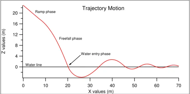
A freefall lifeboat experiences projectile motion when it leaves the end of the launch ramp. The simulated data shows that the simulated lifeboat also experiences this motion, as can be seen in figure 7.1.
20 16 12 8 4 0 Z values ( m ) 70 60 50 40 30 20 10 0 X values (m) Trajectory Motion Water line Ramp phase Freefall phase
Water entry phase
Figure 5.1 Trajectory motion with normal conditions
In the above figure, the ramp angle is 35°, centre of gravity and ramp offset are normal conditions, and the freefall height is 25m. It can be seen that the simulated lifeboat travels along the launch ramp at 35°, and then experiences an arch motion after leaving the ramp. This is a typical motion subjected to a rigid body in freefall.
5.1.2 Pitch Angle
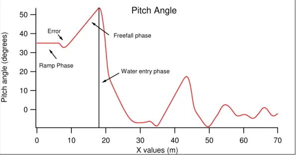
Observed was the change in the pitch angle during the process of the launch. The pitch angle remains the same for the duration the boat is on the launch ramp, and increases when the boat leaves the ramp. This is an expected result. There is one error, namely, a rapid decrease in pitch angle prior to leaving the ramp. The rapid change in pitch angle has not been explained. It has been assumed that the problem is caused by complications with the interaction of the mathematical equations used in the simulation program and the lifeboat design itself. The figure below demonstrates the change in pitch angle with the ramp angle is 35°, centre of gravity and ramp offset are normal conditions, and the freefall height is 25m. 50 40 30 20 10 0 Pitc h an gle ( deg rees ) 70 60 50 40 30 20 10 0 X values (m) Pitch Angle Ramp Phase Error Freefall phase
Water entry phase
Figure 5.2 Change in pitch angle with normal conditions
5.1.3 Velocity
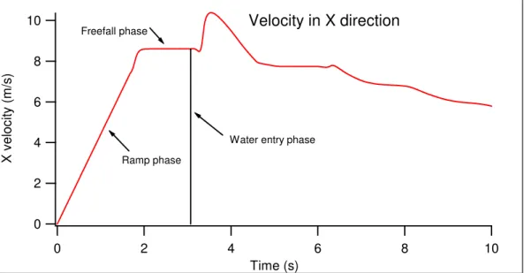
Using the same normal conditions as above, the X velocity and Z velocities were observed and plotted. The velocity in the X direction follows the laws of physics exactly. The velocity increases at a constant rate while the boat is on the launch ramp. The instance the boat leaves the ramp, there is no increase in the X velocity until contact with the water is made.
10 8 6 4 2 0 X v e lo c ity ( m /s) 10 8 6 4 2 0 Time (s) Velocity in X direction Ramp phase Freefall phase
Water entry phase
Figure 5.3 X velocity with normal conditions
The Z velocity is also correct. The boat’s velocity increases at a constant rate while on the launch ramp. Once the boat leaves the ramp, the boat experiences projectile motion in which the Z velocity increases at a great constant rate until the boat makes contact with the water and the velocity decreases to zero. This can be seen in the following figure.
-15 -10 -5 0 5 Z veloc ity ( m /s ) 10 8 6 4 2 0 Time (s) Velocity in Z direction Ramp phase Freefall phase
Water entry phase
5.1.4 Acceleration
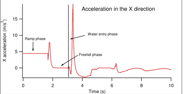
During the ramp phase of the launch, the lifeboat travels at a constant
acceleration in the X direction. This can be seen in the following figure as a flat line. Also observed was that when the lifeboat no longer had contact with the launch ramp, the X velocity remained constant therefore the X acceleration became zero. 15 10 5 0 X ac c e ler a tion ( m /s 2 ) 10 8 6 4 2 0 Time (s)
Acceleration in the X direction
Ramp phase
Freefall phase
Water entry phase
Figure 5.5 Acceleration in the X direction
The Z acceleration also shows the wave trend. When the lifeboat is on the launch ramp it travels at a constant Z acceleration, shown as a flat line in Figure 5.6. When the lifeboat leaves the launch ramp its vertical acceleration increases until the freefall phase begins when the acceleration becomes constant again.
60 40 20 0 -20 Z acc e le ra ti ons ( m /s 2 ) 10 8 6 4 2 0 Time (s)
Acceleration in the Z direction
Ramp phase
Freefall phase Water entry phase
Figure 5.6 Acceleration in the Z direction
5.2 Results of Simulation Matrix
5.2.1 Change in Centre of Gravity – Series A
Depending on the procedure used to board a freefall lifeboat, the centre of gravity of the lifeboat could be moved forward or aft of the normal position. To simulate this, the centre of gravity of the simulated lifeboat was moved forward (G2) ad aft (G3) of the normal position.
20 15 10 5 0 -5 Z v a lues ( m ) 70 60 50 40 30 20 10 0 X values (m) Water line
Change in centre of gravity
Aft CG travelled furthest in X Trajectory
Aft Normal Fwd
Figure 5.7 Effect of change in CG on trajectory of the lifeboat As can be seen in the above figure, the lifeboat travels the greatest distance in the X direction when the centre of gravity is in the aft position. Since the center of gravity of the lifeboat remains on the launch ramp longer with the aft position, the boat is able to have a greater velocity in the X direction at the end of the ramp, allowing the boat to travel further.
40 20 0 -20 -40 P itch an gle ( d e g re es) 70 60 50 40 30 20 10 0 X values (m)
Change in centre of gravity Pitch angle Normal CG greatest increase in pitch Aft Normal Fwd
The normal position of the lifeboat’s centre of gravity produced the greatest increase in pitch angle, which could possibly be incorrect. The pitch angle increases the most during the rotational phase of the launch, which starts when the CG passes over the end of the launch ramp and ends when the lifeboat no longer has contact with the ramp. The forward position of the CG, therefore, creates the largest pitch angle.
5.2.2 Change in Ramp Angle – Series B
The angle of the launch ramp can often be different on each offshore installation, depending on the manufacturer design. The angle could also be changed due to damage to the installation. In the simulations, series B compares three different launch ramp angles (L25, L35, and L45) with the lifeboat in normal conditions.
20 15 10 5 0 Z v a lu es ( m ) 70 60 50 40 30 20 10 0 X values (m) Change in ramp angle
Trajectory
25° travelled furthest in X direction
Water line
25° 35° 45°
Figure 5.9 Effect of change in ramp angle on trajectory of the lifeboat It can be seen that with a decrease in ramp angle, the distance traveled by the lifeboat away from the installation increases, however, the time before water entry is increased. The same concept is used for an increase in ramp angle. The boat has a larger Z velocity at the beginning of the freefall phase, therefore the boat makes contact with the water surface faster, and does not travel as far in the X direction.
50 40 30 20 10 0 P itch a n g le ( d eg re es) 70 60 50 40 30 20 10 0 X values (m)
Change in ramp angle Pitch angle
25° has the largest increase in pitch
25° 35° 45°
Figure 5.10 Effect of change in ramp angle on pitch angle of the lifeboat Decreasing the speed at which the lifeboat leaves the launch ramp, increases the change in pitch experienced by the lifeboat during the freefall phase. This result is caused by the reduction in ramp angle.
5.2.3 Change in Ramp Offset – Series C
Depending on the manufacturer of the launch system, installations may have different ramp offsets. Series C simulates this change in initial condition. During these simulations, the lifeboat is held in all normal conditions, and the freefall height is maintained at 25m.
20 15 10 5 0 Z v a lu e s ( m ) 70 60 50 40 30 20 10 0 X values (m) Water line
Change in ramp offset Trajectory
increase in ramp offset increased X distance
Aft Normal Fwd
Figure 5.11 Effect of change in ramp offset on trajectory of the lifeboat With increase in ramp offset, the velocity experienced by the lifeboat at the end of the launch ramp increases. This allows the boat to project further away from the installation. The opposite occurs with a decrease in ramp offset.
50 40 30 20 10 0 P it ch an g le ( d eg re e s) 70 60 50 40 30 20 10 0 X values (m)
Change in ramp offset Pitch angle
decrease in ramp offset increases pitch Aft Normal Fwd
Figure 5.12 Effect of change in ramp offset on pitch angle of the lifeboat By decreasing the offset of the launch ramp, it can be seen in Figure 5.12 that the pitch angle of the lifeboat increases more rapidly compared to the other ramp offsets. Again, this was caused by the fact that the lifeboat left the launch ramp at a slower speed.
6.0 CONCLUSIONS
After carefully studying the graphical data, it can be clearly seen that the simulated model follows the appropriate projectile motion that was predicted. This can be observed from the graphs in section 5.1 above.
During the simulations, it was observed that distance the lifeboat traveled away from the installation, and the pitch angle that the boat experience after leaving the launch ramp can be credited to the speed of the lifeboat at the end of the ramp phase.
It was seen that with a greater X velocity, the greater the distance the boat traveled away from the installation. This was a factor of a smaller ramp angle, longer ramp offset, and a centre of gravity closer to the stern.
It was also observed that the pitch angle was increased when there was a smaller Z velocity component at the end of the ramp phase. This rapid change in pitch was attributed to a larger X velocity component, credited to a smaller ramp angle, longer ramp offset, and a centre of gravity closer to the stern.
Greater launch distance produces a larger increase in pitch angle. For a successful launch to occur, there must be a happy median created between these two variables.
Since the data of the Phase 3 freefall lifeboat is currently being calibrated and analyzed, there is no data available to do a comparison of the physical model testing and the simulated tests.
This procedure can be further developed in the future to predict the behaviour of new designs of freefall lifeboats, and can be used to aid in physical model testing to generated additional data.
7.0 REFERENCES
• Nelson, J. K., Hirsch, T. J. (1991) Freefall – A Launch Predication Model For Free-Fall Lifeboats, Clemson University, South Carolina USA.
• Simões Ré, A., Veitch, B., Pelly, D., Mulrooney, S., Hopkins, T., (2003) – Model Testing of a Freefall Lifeboat Evacuation System in a Range of Initial Conditions, IOT Report Number LM-2003-33
Appendix 1
Copy r i ght , 2002, Bas eLi ne Tec hnol ogy I nput s Di s pl ac ement 4. 94 Dr af t Tr i m LCG Dept h 134. 4 Li near uni t s , Model mm. Li near uni t s , Out put mm. Wei ght uni t s , I nput Kg. Wei ght uni t s , Out put Kg. Out put s
Lengt h, Ov er al l . . . 865mm Wat er pl ane Ar ea. . . 134725. 42 Sq mm Beam. . . 251mm Kg/ Cm I mmer s i on. . . 1. 35 Kg Dept h, Mi dhs i p. . . 255mm LCB. . . 361. 01 mm Lengt h, Wat er l i ne. . . 816. 65 mm VCB. . . 44. 82 mm Beam, Wat er l i ne. . . 216. 42 mm LCF. . . 349. 20 mm Bas el i ne Dr af t . . . 67. 97 mm Mom t o t r i m 1 c m. . . 139. 73 mm. - k g Fai r body Dr af t . . . 67. 97 mm Tr i m, Degr ees . . . 0. 00 Di s pl ac ement . . . 4. 94 Kg Tr i m, . . . 0. 00 mm Vol ume. . . 0. 17 Cu mm BMt . . . 0. 27 mm Di s p/ 0. 01L^ 3. . . 253. 04
Rat i os
Under body Hul l
Lengt h / Br eadt h. . . 7. 5467 Lengt h / Beam. . . 1. 7381 Br eadt h / Dr af t . . . 1. 5921 Beam / Dept h. . . 0. 0121 Lengt h / Dr af t . . . 12. 0152 Lengt h / Dept h. . . 0. 0211 Coef f i c i ent s
Bl oc k Coef f i c i ent . . . 0. 4118 Di s p/ 0. 01L^ 3. . . 253. 04 Mi ds hi p Coef f i c i ent . . . 0. 6187 Pr i s mat i c Coef f i c i ent . . . 0. 6656 Wat er pl ane Coef f i c i ent . . . 0. 7623
PROJECT PARTICULARS MODEL PARTICULARS
PROJECT DISCRIPTION LWL(m) 0.825
PROJECT NUMBER Pj874_PERD LOA (m) 0.865
MODEL DESCRIPTION BEAM (m) 0.251
MODEL NUMBER DEPTH MLD (m) 0.255
DATE DRAFT (m) 0.067
DISPLACEMENT (kg) 4.939
TARGET VALUES
LCG (m) wrt AP 0.350
VCG (m) wrt Baseline 0.115 approx. 98% of design draft monohull uniform loading
Radius of Gyration (m) 0.216
VALUES TO BE INPUTED
Acceleration due to gravity (g) = 9.807 Measured mass of model (kg) = 5.026
LIST OF TERMINOLOGY KE = Knife edge
GoBo = Restoring moment of frame without model
GsBs = Restoring moment of frame model, and trimming mass GcBc = Restoring moment for trimming mass used to level model GmBm = Restoring moment for the model
Jo = Mass moment of inertia of frame without model
Js = Mass moment of inertia of frame with model, and trimming mass Jc = Mass moment of inertia of trimming mass used to level model Jm(ke) = Mass moment of inertia of model about the knife edge Jm(vcg) = Mass moment of inertia of model about the VCG K = Radius of Gyration
T = Period
ESTABLISHING RESTORING MOMENT & MASS MOMENT OF INERTIA FOR FRAME
GoBo=(Z+L/TAN$ )*P*g= 7.841
Jo=(T/2pie)^2*GoBo= 0.376
Applied Load {P} (kg)= 0.247
Transverse distance to applied load from KE* {L} (m)= 0.158
Vertical distance to applied load from KE {Z} (m)= 0.030
Inclining Angles (Degrees)
Actual Angle (Deg.) Change in Angle (Deg.)
Initial Angle -0.580 Apply Load -3.420 2.840 Remove Load -0.600 2.820 Apply Load 2.210 2.810 Remove Load -0.580 2.790 Mean Angle= 2.815 Period (T) of Frame
Cycles Time (sec) Period (sec)
10 13.870 1.387
10 13.710 1.371
10 13.680 1.368
Js=(T/2pie)^2*GsBs= 0.701
Applied Load {P} (kg)= 0.911
Transverse distance to applied load from KE* {L} (m)= 0.158
Vertical distance to applied load from KE {Z} (m)= 0.030
Inclining Angles (Degrees)
Actual Angle (Deg.) Change in Angle (Deg.)
Initial Angle -0.590 Apply Load -4.720 4.130 Remove Load -0.590 4.130 Apply Load 3.590 4.180 Remove Load -0.570 4.160 Mean Angle= 4.150 Period (T) of Frame
Cycles Time (sec) Period (sec)
10 11.750 1.175
10 11.900 1.190
10 11.900 1.190
Mean= 1.185
CORRECTION FOR TRIMMING MASS
GcBc=mass*distance*g= 0.000
Jc=mass*distance^2= 0.000
Triming Mass (Kg)=
VCG of Trim mass wrt KE (m)= TCG of Trim mass wrt KE (m)=
ESTABLISHING RESTORING MOMENT & MASS MOMENT OF INERTIA FOR MODEL
GmBm=GsBs-GoBo-GcBc= 11.877
Jm(ke)=Js-Jo-Jc = 0.326
VCG OF MODEL
distance from baseline to KE (m) = 0.358 * calculated with model mounted transversely
CG wrt KE=GmBm/(displacement*g)= 0.241
VCG of model from baseline = 0.117
K=(Jm(vcg)/displacement)^0.5 = 0.082
SUMMARY
TARGET ACTUAL PERCENT ERROR
VCG (m) wrt Baseline 0.115 0.117 1.765
PROJECT PARTICULARS MODEL PARTICULARS
PROJECT DISCRIPTION LWL(m) 0.825
PROJECT NUMBER Pj874_PERD LOA (m) 0.865
MODEL DESCRIPTION BEAM (m) 0.251
MODEL NUMBER DEPTH MLD (m) 0.255
DATE DRAFT (m) 0.067
DISPLACEMENT (kg) 4.939
TARGET VALUES
LCG (m) wrt AP 0.350
VCG (m) wrt Baseline 0.115 approx. 98% of design draft monohull uniform loading
Radius of Gyration (m) 0.216
VALUES TO BE INPUTED
Acceleration due to gravity (g) = 9.807 Measured mass of model (kg) = 5.026
LIST OF TERMINOLOGY KE = Knife edge
GoBo = Restoring moment of frame without model
GsBs = Restoring moment of frame model, and trimming mass GcBc = Restoring moment for trimming mass used to level model GmBm = Restoring moment for the model
Jo = Mass moment of inertia of frame without model
Js = Mass moment of inertia of frame with model, and trimming mass Jc = Mass moment of inertia of trimming mass used to level model Jm(ke) = Mass moment of inertia of model about the knife edge Jm(vcg) = Mass moment of inertia of model about the VCG K = Radius of Gyration
T = Period
ESTABLISHING RESTORING MOMENT & MASS MOMENT OF INERTIA FOR FRAME
GoBo=(Z+L/TAN$ )*P*g= 7.679
Jo=(T/2pie)^2*GoBo= 0.375
Applied Load {P} (kg)= 0.247
Transverse distance to applied load from KE* {L} (m)= 0.158
Vertical distance to applied load from KE {Z} (m)= 0.030
Inclining Angles (Degrees)
Actual Angle (Deg.) Change in Angle (Deg.)
Initial Angle -0.560 Apply Load -3.420 2.860 Remove Load -0.560 2.860 Apply Load 2.320 2.880 Remove Load -0.580 2.900 Mean Angle= 2.875 Period (T) of Frame
Cycles Time (sec) Period (sec)
10 13.810 1.381
10 14.030 1.403
10 13.840 1.384
Js=(T/2pie)^2*GsBs= 0.891
Applied Load {P} (kg)= 0.911
Transverse distance to applied load from KE* {L} (m)= 0.158
Vertical distance to applied load from KE {Z} (m)= 0.030
Inclining Angles (Degrees)
Actual Angle (Deg.) Change in Angle (Deg.)
Initial Angle 0.030 Apply Load -4.020 4.050 Remove Load 0.060 4.080 Apply Load 4.120 4.060 Remove Load 0.070 4.050 Mean Angle= 4.060 Period (T) of Frame
Cycles Time (sec) Period (sec)
10 13.280 1.328
10 13.150 1.315
10 13.210 1.321
Mean= 1.321
CORRECTION FOR TRIMMING MASS
GcBc=mass*distance*g= 0.000
Jc=mass*distance^2= 0.000
Triming Mass (Kg)=
VCG of Trim mass wrt KE (m)= TCG of Trim mass wrt KE (m)=
ESTABLISHING RESTORING MOMENT & MASS MOMENT OF INERTIA FOR MODEL
GmBm=GsBs-GoBo-GcBc= 12.472
Jm(ke)=Js-Jo-Jc = 0.516
VCG OF MODEL
distance from baseline to KE (m) = 0.358 * calculated with model mounted transversely
CG wrt KE=GmBm/(displacement*g)= 0.253
VCG of model from baseline = 0.105
K=(Jm(vcg)/displacement)^0.5 = 0.196
SUMMARY
TARGET ACTUAL PERCENT ERROR
VCG (m) wrt Baseline 0.115 0.105 -8.733
Appendix 2
3 0.704800414 1.686456745 0.046376783 4 6.027192033 1.602880819 0.046376783 5 0.704800414 1.686456745 0.650276294 6 0.704800414 1.602880819 0.650276294 7 3.337011956 1.602880819 0.110477726 8 6.027192033 1.602880819 0.046576907 9 10.90530396 1.685401026 2.178032266 10 10.28801086 1.020950736 2.027388011 11 11.29025015 1.685397472 2.254953967 12 9.69307625 1.006707425 1.949168879 13 9.167989669 0.557019395 1.874415489 14 0.044657064 1.685397472 1.60379613 15 1.062553859 0.449750235 1.606851315 16 1.061453708 1.68323627 1.60606397 17 0.044645511 0.315476724 1.605214419 18 2.774459814 0.344692041 1.620520558 19 3.400248419 0.072400951 1.621849981 20 3.785052425 0.321544439 1.630741831 21 7.458383545 0.321508893 1.739864718 22 7.978778045 0.286981215 1.77014464 23 6.763582241 0.155740673 1.693407779 24 6.077080945 0.360476275 1.679910935 25 8.478040404 0.612433945 1.817595092 26 8.352989322 0.604412974 1.807873241 27 1.28417118 0.907340157 3.038193898 28 1.270125149 0.815350476 2.950626149 29 1.28417118 0.877987988 3.016510794 30 1.28417118 0.946872721 3.058117472 31 1.256116442 0.763792676 2.875428433 32 1.28417118 1.006270208 3.074699715 33 1.28417118 1.093544703 3.087176386 34 1.228164788 0.687000718 2.70471842 35 1.28417118 1.685397472 3.104629508 36 1.172201052 0.593290608 2.331431341 37 1.059919895 1.685397472 1.603246944 38 1.059907454 0.449297023 1.603364246 39 1.592208111 1.029192093 3.360756732 40 1.472469389 1.029192093 3.197849083 41 1.592206334 0.910126969 3.360756732 42 1.685784924 0.910126969 3.402434502 43 1.689357304 1.029192093 3.402434502 44 1.403963221 0.910361573 3.106264627 45 1.403805041 0.756175152 3.096080677 46 1.472469389 0.755496222 3.187149715 47 1.681869524 0.755277614 3.388393804 48 1.472469389 0.910126969 3.197849083 49 1.404007653 1.029234748 3.106495677 50 1.592204556 0.755318492 3.347391409 51 1.680876011 0.688134638 3.303047684 52 1.472469389 0.689679115 3.122189267 53 1.592204556 0.688422561 3.26620418 54 1.403691293 0.691849202 3.039935656 55 2.106797937 0.910126969 3.404460628 56 2.13432837 1.029192093 3.404460628
60 2.786172245 1.029192093 3.404318444 61 2.654651777 0.755277614 3.390242199 62 2.637216429 0.688125751 3.304718349 63 2.887425232 0.910126969 3.399590816 64 2.959086114 1.029192093 3.399590816 65 2.808886186 0.755275837 3.385603437 66 2.788962612 0.688118642 3.300523913 67 1.472469389 0.638517653 3.008655112 68 1.403586432 0.643275495 2.942486099 69 1.472961702 0.531577294 2.523149083 70 1.592655991 0.523387479 2.559459396 71 1.592204556 0.63537538 3.124304259 72 1.40367352 0.541858995 2.502621226 73 2.628756464 0.634628912 3.155264888 74 2.622500355 0.512707661 2.570976323 75 2.772096001 0.51139068 2.57014099 76 2.065280124 0.634623581 3.155353753 77 2.062774126 0.517573919 2.569998806 78 1.247450309 0.759928818 2.865333348 79 1.228721084 0.696601712 2.734665986 80 1.261267068 0.829478263 2.965448861 81 1.270478832 0.894826162 3.029858344 82 1.273544681 0.924659981 3.048928812 83 1.275832071 0.953903735 3.061654306 84 1.280849399 1.084295615 3.08497253 85 1.398396706 1.685397472 3.10487833 86 1.401402126 1.685397472 3.105056061 87 1.401985082 1.685397472 3.105233791 88 1.402603584 1.685397472 3.105553706 89 1.40412851 1.685397472 3.106797818 90 1.419818546 1.685397472 3.126543661 91 1.534708784 1.685397472 3.282590919 92 1.593921432 1.685397472 3.363013908 93 1.604707887 1.685397472 3.375774948 94 1.616795329 1.685397472 3.385603437 95 1.632657764 1.685397472 3.392854836 96 1.654772753 1.685397472 3.397937924 97 1.855238383 1.685397472 3.40435399 98 2.307668792 1.685397472 3.404460628 99 2.840024545 1.685397472 3.404407309 100 3.184714809 1.685397472 3.404194033 101 3.296507206 1.685397472 3.402701098 102 3.304576165 1.685397472 3.401794673 103 3.309108289 1.685397472 3.400479468 104 4.003216444 1.082461437 2.761218902 105 3.414644578 1.685397472 3.334665915 106 3.317301659 1.685397472 3.395609656 107 3.687318499 1.685397472 3.163244981 108 4.325032811 1.685397472 2.76137886 109 3.83360836 0.76438274 2.753700908 110 3.80709099 0.699443621 2.737100892 111 2.779311853 0.634612917 3.151888011 112 3.791663995 0.623081771 2.677703405 113 3.797973423 0.663844229 2.714973462
117 3.78514129 0.427325996 2.117834992 118 3.149044325 0.334417449 1.619239122 119 3.785034652 0.320965038 1.623209618 120 2.876974687 0.34103435 1.617463595 121 2.779791725 0.34384249 1.61678822 122 2.685310265 0.348292858 1.615890682 123 2.451434882 0.359756467 1.613583742 124 2.090411198 0.377472629 1.610016693 125 1.783559728 0.392524613 1.60698639 126 1.680396139 0.634655572 3.153896364 127 1.68045479 0.520979233 2.568861332 128 1.646010646 0.399390337 1.605648081 129 1.422592917 0.41633515 1.604151591 130 1.389700359 0.419159286 1.604126709 131 1.323262973 0.425522032 1.604076944 132 1.1854704 0.618464336 2.440113458 133 1.138096372 0.550155449 2.114866895 134 1.064037908 0.448587879 1.603828122 135 4.352438833 0.592585018 2.605153872 136 6.617256834 0.822033138 2.597404828 137 4.368985529 0.693809568 2.705162746 138 6.423548513 0.688394124 2.531697913 139 6.259521162 0.587876941 2.446316247 140 8.587149073 0.79850697 2.020261024 141 3.785283475 0.47824219 2.30139491 142 3.785087971 0.416944765 2.038478386 143 4.338291496 0.489380551 2.353345495 144 4.344281009 0.530192774 2.483532985 145 6.129529175 0.51962315 2.337403081 146 3.786794183 0.56272454 2.572007159 147 4.066541772 1.204688384 2.762125327 148 4.468941085 1.685269506 2.753949731 149 4.325761505 1.685246401 2.76137886 150 4.809099224 1.685326379 2.735288043 151 3.912680598 0.914660871 2.759459372 152 6.030124584 1.685505887 2.684723755 153 5.337047264 1.685408135 2.710619068 154 7.430124417 1.685608971 2.636221139 155 8.420189171 1.685528992 2.586723233 156 9.435136176 1.186721622 2.217381768 157 9.917318648 1.685415245 2.426534858 158 9.229413282 1.685454345 2.517870491 159 10.48027957 1.685401026 2.31374717 160 10.9146348 1.685397472 2.180627129 161 9.665279222 0.990315354 1.94929329 162 8.971970853 0.968765547 2.110761324 163 8.878538002 0.731163159 1.840006891 164 3.835350118 0.761544387 2.750821676 165 3.816368515 0.719571584 2.743463639 166 3.805704693 0.691717682 2.733670696 167 3.799768499 0.671280468 2.72110516 168 3.795591836 0.652794733 2.705589299 169 3.790224379 0.618716713 2.667092903 170 8.330239835 0.697310856 1.956420278
174 7.434301081 0.484420097 1.73675266 175 6.172451058 0.364363238 1.673292257 176 5.231510976 0.329972413 1.629725213 177 4.885487734 0.32603213 1.625239299 178 4.421309348 0.323417717 1.623701931 179 3.994329926 0.321350713 1.623712595 180 3.785052425 0.318921139 1.623668162 181 0.044545805 0.6869865 1.605210864 182 0.044629871 0.41436412 1.4051238 183 0.044670216 0.316457796 1.605529002 184 0.044506882 0.925925421 1.604510607 185 0.044551492 1.185484619 1.603492212 186 0.044618141 0.464654704 1.302168156 187 0.044590948 1.685383253 1.489664801 188 0.044590948 1.685390362 1.605529002 189 0.044590948 1.685397472 1.252831985 190 0.044625428 0.485884595 1.258677536 191 0.044625428 0.48588815 1.258670427 192 0.044625428 0.485898814 1.258656209 193 0.044625072 0.485968129 1.258578007 194 0.044624184 0.486490656 1.258011048 195 0.044621162 0.490610446 1.253612221 196 0.044616897 0.523451462 1.218682873 197 0.044659908 1.685383253 0.691115176 198 0.044625428 0.612515701 1.124021905 199 0.044659908 0.785911219 0.93976173 200 1.737577329 0.344226388 1.085294459 201 0.875625951 0.356953659 1.241915786 202 0.875645502 0.457675232 1.108783304 203 1.73742448 0.261109007 1.223856604 204 2.540300063 0.263076482 1.056626552 205 2.540086786 0.192976072 1.202927077 206 3.394063402 0.222347792 1.034596873 207 3.393885672 0.158487673 1.185577039 208 4.740050979 0.219576976 1.021281315 209 4.739926568 0.156226588 1.172629382 210 6.316483743 0.30010838 1.027007787 211 6.316785884 0.228257326 1.180884957 212 8.058650069 0.621738129 1.098814408 213 8.081204052 0.529115729 1.271682067 214 9.329599887 1.049512005 1.174284051 215 0.883325231 0.881563923 0.821839412 216 0.044659908 0.792476579 0.937961321 217 0.044659908 1.202068639 0.82477374 218 0.044659908 0.786465738 0.939656869 219 0.044659908 0.785888114 0.939838154 220 0.044659908 0.78579214 0.939902137 221 0.044659908 0.785833018 0.939866591 222 0.044659908 0.77343988 0.952988423 223 0.044659908 0.581352459 1.156873585 224 0.044659908 0.485985902 1.258426937 225 0.044913173 0.422832972 1.387990593 226 0.38739887 0.273788291 1.604606581 227 0.045342037 0.31646135 1.605521892
231 2.283568555 0.113639727 1.610597871 232 2.885416879 0.090658658 1.617426272 233 3.790864208 0.072190518 1.623613066 234 5.063857925 0.074649951 1.637872373 235 6.415035228 0.1346471 1.682534235 236 7.46005421 0.220767769 1.729037385 237 8.203731364 0.322523733 1.770727596 238 8.805490823 0.445546912 1.815089094 239 9.455752898 0.914383611 1.460449484 240 9.911435773 0.827661859 1.947231618 241 10.88598467 1.685397472 1.292634699 242 10.41469707 1.492883498 1.245514826 243 10.75814322 1.685397472 1.064114332 244 11.03115483 1.685397472 1.616077299 245 10.62555637 1.414506186 1.707034366 246 10.52058882 1.15864378 2.063591686 247 10.56187558 1.685397472 0.761743445 248 1.737755059 0.736735005 0.750455789 249 2.540300063 0.592151356 0.689531599 250 3.394063402 0.513272844 0.661343563 251 4.739500015 0.50045493 0.652019828 252 6.308965749 0.590798828 0.652976018 253 7.983914452 0.918892631 0.667935582 254 9.030621872 1.285152251 0.645342499 255 9.929848638 1.56900008 0.545310519 256 10.35115846 1.685397472 0.498227969 257 9.71701653 1.594331989 0.358556787 258 10.06291536 1.685397472 0.271598653 259 10.22255277 1.685397472 0.378377277 260 9.86856721 1.685397472 0.186318293 261 9.640841297 1.685397472 0.123268092 262 9.372468451 1.685397472 0.076813641 263 8.433909955 1.685397472 0.045119874 264 8.956703815 1.685397472 0.045843592 265 8.147497477 1.685397472 0.045691277 266 8.863128779 1.388497125 0.444340123 267 7.77749841 1.685397472 0.04636914 268 7.912502393 1.109504889 0.46964004 269 7.555673145 1.685397472 0.046376783 270 7.15325606 1.685397472 0.046376783 271 6.297395502 0.815560198 0.485913032 272 6.809952093 1.685397472 0.046376783 273 6.331484185 1.685397472 0.046385314 274 5.054864769 1.685397472 0.050735798 275 4.738522498 0.725637522 0.489424984 276 3.796231665 1.685472118 0.079426099 277 3.394063402 0.744173021 0.504542729 278 2.893165923 1.685896894 0.16365465 279 2.540300063 0.832451692 0.549796433 280 2.291353145 1.68638032 0.287489524 281 1.738044759 0.984441365 0.64528918 282 1.809295084 1.686412312 0.416112987 283 0.945031435 1.685669399 0.614516945 284 0.895821452 1.115046522 0.751045854
1 1 2 3 2 4 2 1 3 5 2 3 4 6 2 5 5 7 4 8 6 7 2 4 7 6 2 7 8 9 10 11 9 12 10 9 10 13 10 12 11 14 15 16 12 17 15 14 13 17 18 15 14 19 18 17 15 20 18 19 16 21 22 13 17 21 23 22 18 24 23 21 19 24 19 23 20 20 19 24 21 25 12 26 22 25 13 12 23 26 13 25 24 26 21 13 25 24 21 26 26 27 28 29 27 30 28 27 28 30 31 28 29 32 31 30 30 33 31 32 31 33 34 31 32 35 34 33 33 35 36 34 34 37 36 35 35 38 36 37 36 39 40 41 37 42 39 41 38 43 39 42 39 44 45 46 40 41 47 42 41 48 40 49 42 48 41 40 43 50 41 48 44 50 47 41 45 51 47 50 46 46 52 53 47 45 52 46 48 45 54 52 49 43 55 56 50 42 55 43 51 42 57 55 52 47 57 42 53 47 58 57 54 51 58 47
58 57 61 55 59 57 62 61 60 58 62 57 61 60 63 64 62 59 63 60 63 59 65 63 64 61 65 59 65 61 66 65 66 62 66 61 67 67 68 69 68 70 67 69 69 71 67 70 70 68 72 69 71 73 74 75 72 76 74 73 73 76 77 74 74 54 78 79 75 45 78 54 76 45 80 78 77 45 81 80 78 44 81 45 79 44 82 81 80 83 82 44 81 50 53 51 82 50 46 53 83 48 46 50 84 48 44 46 85 49 44 48 86 49 83 44 87 84 83 49 88 85 84 49 89 35 84 85 90 49 86 85 91 49 87 86 92 88 87 49 93 49 89 88 94 49 90 89 95 40 90 49 96 40 91 90 97 39 91 40 98 39 92 91 99 93 92 39 100 39 94 93 101 39 95 94 102 43 95 39 103 43 96 95 104 43 97 96 105 56 97 43 106 56 98 97 107 56 99 98 108 60 99 56 109 60 100 99 110 60 101 100 111 64 101 60
115 104 107 105 116 108 107 104 117 64 106 103 118 64 104 106 119 63 104 64 120 63 109 104 121 65 109 63 122 65 286 109 123 65 110 286 124 66 110 65 125 111 112 113 126 111 114 112 127 115 114 111 128 75 111 73 129 75 115 111 130 116 115 75 131 117 118 119 132 116 118 117 133 116 120 118 134 75 120 116 135 75 121 120 136 75 122 121 137 74 122 75 138 74 123 122 139 77 123 74 140 77 124 123 141 125 124 77 142 126 77 76 143 127 77 126 144 127 125 77 145 128 125 127 146 71 127 126 147 70 127 71 148 70 128 127 149 69 128 70 150 69 129 128 151 72 129 69 152 72 130 129 153 131 130 72 154 66 113 110 155 66 111 113 156 62 111 66 157 62 73 111 158 58 73 62 159 58 76 73 160 51 76 58 161 51 126 76 162 53 126 51 163 53 71 126 164 52 71 53 165 52 67 71 166 54 67 52 167 54 68 67 168 79 68 54
172 133 131 132 173 134 131 133 174 135 136 137 175 135 138 136 176 139 138 135 177 139 140 138 178 141 142 143 179 144 143 145 180 144 141 143 181 146 141 144 182 147 148 149 183 147 150 148 184 151 150 147 185 137 152 153 186 136 152 137 187 136 154 152 188 155 154 136 189 156 157 158 190 159 157 156 191 156 160 159 192 156 161 160 193 162 161 156 194 136 158 155 195 136 156 158 196 138 156 136 197 138 162 156 198 140 162 138 199 140 161 162 200 163 161 140 201 151 153 150 202 151 137 153 203 164 137 151 204 165 137 164 205 166 137 165 206 167 137 166 207 168 137 167 208 169 137 168 209 169 135 137 210 146 135 169 211 144 135 146 212 144 139 135 213 145 139 144 214 145 140 139 215 170 140 145 216 170 163 140 217 171 163 170 218 172 171 170 219 173 171 172 220 170 174 172 221 170 175 174 222 145 175 170 223 145 176 175 224 143 176 145 225 143 177 176
229 180 179 142 230 181 182 183 231 184 182 181 232 185 182 184 233 186 182 185 234 187 185 188 235 187 186 185 236 189 186 187 237 189 190 186 238 191 190 189 239 189 192 191 240 189 193 192 241 194 193 189 242 189 195 194 243 189 196 195 244 197 196 189 245 197 198 196 246 199 198 197 247 200 201 202 248 200 203 201 249 204 203 200 250 204 205 203 251 206 205 204 252 206 207 205 253 208 207 206 254 208 209 207 255 210 209 208 256 210 211 209 257 212 211 210 258 212 213 211 259 214 213 212 260 215 216 217 261 215 218 216 262 219 218 215 263 202 220 221 264 222 220 202 265 202 223 222 266 202 224 223 267 201 224 202 268 225 226 227 269 228 226 225 270 224 226 228 271 201 226 224 272 201 229 226 273 203 229 201 274 203 230 229 275 203 231 230 276 205 231 203 277 205 232 231 278 207 232 205 279 207 233 232 280 209 233 207 281 209 234 233 282 211 234 209
286 213 237 236 287 213 238 237 288 214 238 213 289 239 238 214 290 240 238 239 291 241 242 243 292 244 242 241 293 244 245 242 294 11 245 244 295 246 245 11 296 240 245 246 297 239 245 240 298 239 242 245 299 214 242 239 300 214 243 242 301 247 243 214 302 215 221 219 303 215 202 221 304 248 202 215 305 248 200 202 306 249 200 248 307 249 204 200 308 250 204 249 309 250 206 204 310 251 206 250 311 251 208 206 312 252 208 251 313 252 210 208 314 253 210 252 315 253 212 210 316 254 212 253 317 254 214 212 318 255 214 254 319 255 247 214 320 256 247 255 321 257 258 259 322 257 260 258 323 261 260 257 324 262 263 264 325 261 263 262 326 257 263 261 327 257 265 263 328 266 265 257 329 266 267 265 330 268 267 266 331 268 269 267 332 270 269 268 333 271 270 268 334 272 270 271 335 271 273 272 336 271 274 273 337 275 274 271 338 275 276 274 339 277 276 275
343 281 280 279 344 281 282 280 345 281 283 282 346 284 283 281 347 255 259 256 348 255 257 259 349 254 257 255 350 254 266 257 351 253 266 254 352 253 268 266 353 252 268 253 354 252 271 268 355 251 271 252 356 251 275 271 357 250 275 251 358 250 277 275 359 249 277 250 360 249 279 277 361 248 279 249 362 248 281 279 363 215 281 248 364 215 284 281 365 217 284 215 366 217 283 284 367 285 283 217 18.73430000 35.000000 3.3247200000 0.030000 0.000000 0.000000 0.000000 0.000000 0.000000 0.000000 0.000000 0.000000 4.680000 0.000000 1.5340000 0.000000 28864.97872000 0.000000 103883.3874000000 285 0 0 247 0 0 9.810000 9810.000000