DOE/ET-51013-306
The Design and Performance of a Twenty Barrel
Hydrogen Pellet Injector for Alcator C-Mod
John A. Urbahn Plasma Fusion Center
Massachusetts Institute of Technology Cambridge, MA 02139
May 1994
This work was supported by the U. S. Department of Energy Contract No.
DE-AC02-78ET51013. Reproduction, translation, publication, use and disposal, in whole or in part by or for the United States government is permitted.
THE DESIGN AND PERFORMANCE OF A TWENTY BARREL
HYDROGEN PELLET INJECTOR FOR ALCATOR C-MOD
by
John A. Urbahn
B.S. in Physics, University of Connecticut
B.S. in Mechanical Engineering, University of Connecticut (1984)
Submitted to the Department Of Nuclear Engineering in partial fulfillment of the Requirements for the Degree of
Doctor of Philosophy
in Fusion Technology
at the
Massachusetts Institute of Technology
March 1994
© Massachusetts Institute of Technology 1994
All rights Reserved
Signature of Author
Certified by
Accepted by
Accepted b
/
Department of Nuclear Engineering Dr. Martin J. Greenwald Thesis SupervisorDr. Ian H. Hutchinson Thesis Reader
Allan F. Henry Chairman, Department Committee on Graduate Students
a
THE DESIGN AND PERFORMANCE OF A TWENTY BARREL HYDROGEN PELLET INJECTOR FOR ALCATOR C-MOD
by
John A. Urbahn
Submitted to the Department Of Nuclear Engineering in partial fulfillment of the Requirements for the Degree of Doctor of Philosophy in
Fusion Technology
ABSTRACT
A twenty barrel hydrogen pellet injector has been designed, built and tested both
in the laboratory and on the Alcator C-Mod Tokamak at MIT. The injector functions by firing pellets of frozen hydrogen or deuterium deep into the plasma discharge for the purpose of fueling the plasma, modifying the density profile and increasing the global
energy confinement time.
The design goals of the injector are: 1) Operational flexibility, 2) High reliability, 3) Remote operation with minimal maintenance. These requirements have
lead to a single stage , pipe gun design with twenty barrels. Pellets are formed by in-situ condensation of the fuel gas, thus avoiding moving parts at cryogenic temperatures. The injector is the first to dispense with the need for cryogenic fluids and instead uses a closed cycle refrigerator to cool the thermal system components. The twenty barrels of the injector produce pellets of four different size groups and allow for a high degree of flexibility in fueling experiments. Operation of the injector is under PLC control allowing for remote operation, interlocked safety features and automated pellet manufacturing. The injector has been extensively tested and shown to produce pellets reliably with velocities up to 1400 m/sec.
During the period from September to November of 1993, the injector was successfully used to fire pellets into over fifty plasma discharges. Experimental results include data on the pellet penetration into the plasma using an advanced pellet tracking diagnostic with improved time and spatial response. Data from the tracker indicates pellet penetrations were between 30 and 86 percent of the plasma minor radius. Line averaged density increases of up to 300 percent were recorded with peak densities of just under 1 x 10²' / m3, the highest achieved on C-Mod to date. A comparison is made
between the ablation source function derived from tracker data with that predicted by four different variations of the neutral shield model. Results suggest rapid heat flow from the interior of the plasma maintains temperatures on the ablation flux surface. Localized density perturbations with a specific m=l,n=l structure and location on the q=1 flux surface were observed following injection .
Thesis Supervisor: Dr. Martin Greenwald Titles: Principal Research Scientist
TABLE OF CONTENTS
page
Abstract 2
Chapter 1 : Background and Motivation For Pellet Fueling
1.1) Fusion Essentials 7
1.2) Tokamaks 10
1.3) Alcator C-Mod 12
1.4) Tokamak Fueling 15
1.5) Pellet Injection Experiments 17
1.6) Pellet Injection Experiments on Alcator C-Mod 17 1.7) Objective and Scope of Thesis Research 18
Chapter 2: Injector Design and Engineering
2.1) Introduction 21
2.2) Design Criteria 21
2.3) Design Overview 25
2.4) Barrel and Thermal Systems Design 31
2.5) Closed Cycle Refrigeration 35
2.6) Propellant and Fuel Valves 41
2.7) Process Gas System 44
2.8) Injector Vacuum Systems 46
2.9) Control and Data Acquisition 50
Chapter 3: Injector Thermal Analysis
3.1) Introduction 52
3.2) Equilibrium Hear Loads 57
3.2.2) Convection 58
3.2.3) Radiation 60
3.2.4) Refrigerator Equilibrium Temperature and Heat Load 62
3.3) Temperature Profiles 62
3.3.1) Contact Resistance and Refrigerator to Barrel
Temperature Gradients 62
3.3.2) Barrel Cold Plate Isotherms 65
3.3.3) Barrel Temperature Profiles and Pellet Size 67
3.4) Transient Heat Loads 71
3.5) Experimental Results 74
3.5.1) Refrigerator Cooldown Tests 74
3.5.2) Contact Resistance Measurements 81
Chapter 4: Injector Performance
4.1) The Pellet Freezing Process 85
4.2) Deuterium Pellet Freezing Experiments 86
4.2.1) Initial Results and Changes 86
4.2.2) Pellet Mass vs Freeze Pressure 92
4.2.3) Pellet Size vs Vacuum and Pressurized Holding Times 98 4.2.4) Statistical Data On Pellet Mass Variation and
Barrel Reliability 101
4.3) Hydrogen Freezing Experiments 107
4.3.1) Initial Experiments 107
4.3.2) Hydrogen Freezing Experiments After Thermal
System Changes 107
Chapter 5: Injector Diagnostics
5.1) The Pellet Tracker 116
5.2) Velocity Measurement 132
5.3) Pellet Photography 143
Chapter 6 : Initial Injection Experiments
6.1) Introduction and Scope 147
6.2) Equilibrium Timescale Observations 150
6.2.1) Density Profiles 150
6.2.2) Temperature Profiles 161
6.3) Pellet Transit Timescale Observations 166
6.3.1) Tracker Data; General Observations and Results 166 6.3.2) Pellet Ablation Rate Measurements; A Comparison
of Experimental Measurements with Theoretical Models 172 6.3.3) Density Perturbations On the q=1 Rational Flux Surface 188
Chapter 7: Conclusions 195
References 200
Chapter 1: Background and Motivation
For Pellet Fueling
1.1
Fusion Essentials
Fusion is the process by which two light nuclei join to create a single heavier nuclei plus reaction products and energy. The reactions of greatest interest to fusion researchers are:
2D+2D-+3He(.82MeV)+1n(2.45MeV)
2D+2D-+3T(l.0lMeV)+1H(3.02MeV)
(1.2)
2D+T-+4He(3.5MeV)+'n(14.1MeV) (1.3)
Of these, reaction (1.3) has the largest reaction cross section for temperatures below
twenty keV and is therefore the easiest to achieve in the laboratory. Fusion energy, along with fission and solar are the three most plausible sources for mankind's long term energy needs. Fossil fuels are anticipated to be seriously depleted within one to two centuries (2).Well before that time however , their use is expected to cause serious environmental degradation , only the degree to which is uncertain. Though not technologically mature, fusion is a theoretically attractive energy alternative for three reasons:
1) Abundant fuel Supply: Deuterium is available in enormous quantities since it occurs as .015 percent of all naturally occurring hydrogen (2). Earth's oceans contain enough deuterium to meet the word's energy demand for millions of years. Tritium has a 12.3 year half life, and therefore does not exist naturally in any abundance. It may however be bred in fusion reactors by bombarding lithium with fusion neutrons.
Currently known lithium reserves used in fusion fuel cycles could provide 3000 times the 1970 world energy consumption, and this figure does not include the potential reserve present in sea water [2].
2) Safety: probably a more important issue in the near term than fuel availability, is that of safety. Fusion reactors have a greater inherent safety than fission reactors because fusion reactors operate with radioactive fuel inventories many orders of magnitude smaller than fission reactors , and while tritium is more mobile than fission products , it has a short biological and physical half life. A systems failure in a fusion reactor would , in general, imply a "snuffing out" of the reaction since the reaction conditions are critical and require active systems to maintain them. This is not the case for conventional fission reactors where reactor cooling and shutdown are generally dependent on active systems.
3) Environmental: Fusion reactors cannot be sold to the public as "radiation free"
since neutrons produced in the reaction activate vessel wall materials. Analysis by Holdren [5][2] and others has shown that by carefully selecting the first wall and blanket materials with respect to activation cross section and radioactive half life, the radioactive inventory may be reduced between one and three orders of magnitude compared to fission reactors for equal decay times.
The preceding arguments for the benefits of fusion energy form the motivation for fusion research, the majority of which has been directed towards creating the conditions under which the reaction can be sustained in a controlled way. For deuterium and tritium, the required temperature is between ten and twenty keV and the Lawson parameter, nr , or central density times confinement time must exceed 6 x 10¹⁹ sec/ m3 . These parameters have not been achieved simultaneously to date, but progress towards the goal has been steady as shown in Fig. 1.1.1. Once these conditions are reached in a research facility, there still remains the equally challenging task to design reactors which are both reliable and attractive economically.
Spontaneous fusion does not occur in low temperature matter because of the coulomb energy barrier between nuclei. This barrier may be overcome by supplying reacting nuclei with an energy comparable to the coulomb energy. In thermonuclear fusion, this kinetic energy is not directed as in a beam, but thermal as in the velocity
Reactor/
100-
Con
on
inaccessible
gnitionYear
Region
/....
.9
T-JET
;:
.T
_1991
JET,
ET
0TT
0TFTR.
T
JET
JET
*
E
~TFTReJETo
r0.
1
ALC-C*
JT.
-
DT
JT-.60 /IIDD11-.DI
FT
o
ADII-D
I;*
FT
-
Reactor-relevant
Conditions
DIII-D
-1980
-
ASDEX
Hot ton Mode
ALC-
/SE'
RegionI
2
ASDEX*PLT
PLT
T>Te
0 0 0T10
-_
eTFR
0.01-
TFR/
-1970
T3
I3
0/OD-T
Exp
J"2.2161116
1965
0.1
1
10
100
Central Ion Temperature Ti (keV)
Fig 1.1.1: Fusion figures of of merit. Fusion triple product ng ,Ti versus Ti with the year results were achieved on the right. (extracted from ref. (19) JET-P(92)91)
distribution of a gas. Here however, the temperature must be high enough to create a plasma; a charged collection of nuclei and electrons . Fusion reactions in the plasma
occur primarily between nuclei in the high energy 'tail' of the Maxwellian thermal distribution.
In stars, gravitational forces create the high pressures and temperatures needed to fuse nuclei. Creating these conditions in a reactor using gravitational forces would be impractical because of the scale requirements. A comparison of the electromagnetic and gravitational forces between like nuclei show the electromagnetic force to be a least thirty five orders of magnitude stronger than the gravitational .Because charged particles are confined to move along field lines, magnetic fields may be used to hold the plasma and keep it away from material walls. This approach is termed " magnetic confinement".
1.2
Tokamaks
The magnetic field geometry which has been the most successful at confining plasmas has been that of the Tokamak, the essential components of which are shown in Fig. 1.2.1. In a Tokamak, the plasma is created by filling a toroidal vacuum vessel with a gas such as hydrogen, and inducing a current to flow toroidally by induction. Once the current begins to flow, the gas breaks down and forms a plasma which acts as the secondary of a transformer, the primary being the "ohmic heating coil" usually located within the center of the torus. The plasma thus created is stabilized by a powerful toroidal magnetic field generated by magnets external to the vacuum chamber. The toroidal and ohmic heating coils are complimented by the "equilibrium" field coils. These coils carry current in the toroidal direction and act both to affect the shape of the plasma and to provide radial equilibrium for the plasma. In a modern tokamak, the ohmic heating and equilibrium field coils form an integrated system called the poloidal field system. The combination of plasma current, and currents in the toroidal and poloidal field coils generates the complex magnetic field geometry of a tokamak.
induction coils
poloidal coils
(OkmIC Rr=T1N&)toroidal
coils
V4CLAU m
vessI
induced current
Fig. 1.2.1: Schematic drawing of a tokamak showing the toroidal, poloidal and OH
field coils.
This field can best be visualized as a series of nested and closed toroidal helices, where the degree of twist increases towards the center of the plasma cross section. Since the plasma current in a tokamak is driven inductively, reactor designs must operate with either a finite pulse length or employ some form of non-inductive current drive. Plasma heating by current flow becomes less effective as temperatures rise, therefore most advanced tokamaks have some form of auxiliary heating installed either in the form of
neutral beam injection or radio frequency heating.
1.3
Alcator C-Mod
The Alcator C-Mod tokamak is the third in a series of tokamak experiments at MIT designed to investigate the compact, high field approach towards tokamak design. Alcator C, the predecessor to C-Mod, achieved a record Lawson parameter, n r of 8 x
1019 sec / m', a value in excess of the Lawson Parameter. Both Alcators A and C were
of conventional circular cross section and employed toroidal field coils of Bitter plate construction.
The Alcator C-Mod design is similar to Alcator A and C in its high field compact design but differ in that it incorporates the successful design features of more modern tokamaks. These features include a non-circular , or shaped plasma cross section, a poloidal divertor, and strong ICRF heating. The C-Mod vacuum vessel and coil configuration (shown in figure 1.3.1) also provides for greater access to the plasma, allowing greater freedom in the design and implementation of plasma diagnostics and heating methods.
The C-Mod toroidal field system consists of twenty jointed toroidal field coils of six turns each. The coils represent a novel design approach in that the coils are composed of a central core with separate outer horizontal and vertical coil segments. These segments are connected with sliding joints capable of carrying high current density. The sliding joints allow for a toroidal coil system which is demountable permitting the installation of a single piece vacuum vessel and internal poloidal field coils. The magnetic forces on the TF coils are taken in part, by a massive stainless steel
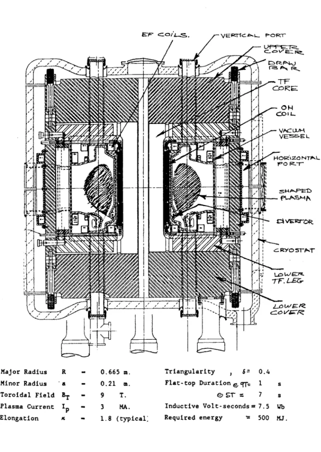
EF CO L VEetC... Pom-r L>fI ... ro W E-re. r7 t Major Radius Minor Radius Toroidal Field Plasma Current Elongation R -a BT Ip IC - 0.665 m. - 0.21 m. - 9 T. - 3 MA. - 1.8 (typical: Triangularity , S= Flat-top Duration e 9T= e S1- = Inductive Volt-seconds-Required energy
Fig. 1.3.1: Cross section of the Alcator C-Mod tokamak and machine parameters. 0.4 1 7 7.5 500 S s Wb miJ.
external superstructure. Permitting the coils to bear directly against this superstructure reduces the TF coil internal forces. The single piece vacuum vessel design allows far greater structural integrity than a segmented vessel. This gives the vessel greater rigidity when subjected to eddy current induced forces and allows the vessel to serve as the structural mount for the poloidal field coils.
The poloidal field coils consist of an upper and lower set of five coils each. These coils acting together with the ohmic heating coils provide for plasma shaping, stability, and current control. The size and current requirements of these coils are greatly reduced
by the close proximity to the plasma afforded by the demountable toroidal field magnets.
The objectives of the Alcator program may be broadly separated into four groups:
1) Explore the confinement properties of a compact ohmically heated, high field tokamak with advanced shaping and a single piece vacuum vessel.
2) Study ICRF heating on high density, shaped tokamak plasmas and establish its' applicability to ignited reactor like plasmas.
3) Investigate different regimes of divertor operation on C-Mod and study the effect on confinement with and without auxiliary heating. Divertor operation on C-Mod could provide results relevant to the design of the ITER divertor configuration.
4) Investigate the control of density profiles (via pellet injection) and temperature and current profile (via RF heating) and its effect of stability and confinement. The effect of plasma shaping plus edge and impurity control will also be explored.
1.4 Tokamak Fueling
In any steady state or long pulse reactor, fuel Ions lost through D-T fusion must be replaced. As an example, to generate 1 GW of power, a reactor would need to fuse about .002 grams per second of deuterium and tritium. The actual fueling rate required could be two orders of magnitude greater since most fuel ions are pumped away before undergoing fusion. Short pulse length experiments also require some form of fueling to maintain density profiles because energetic fuel ions are buried in the first few micro meters of the vacuum chamber or limiter.
Fueling of tokamak discharges may be done with edge fueling by gas puffing or
by direct injection with either neutral beams or solid pellets. Plasmas are gas fueled when neutrals enter the tokamak and ionize forming a cold plasma at the edge of the discharge. These ions diffuse inwards against the density gradient. Inward diffusion may be assisted by ExB drifts in the radial direction. Experiments performed on Alcators A and C showed anomalous radial particle transport whereby fuel ions were convected radially inwards at a rate much greater than that predicted by neoclassical theory [2] . One worrisome aspect in all this is that the same anomalous transport processes which are so helpful in converting fuel ions inwards from the plasma edge may also convect energy away from the plasma core. Therefore, measures which improved energy confinement might decrease the effectiveness of gas fueling.
Modern tokamaks such as Alcator C-Mod employ highly pumped diverted discharges. Gas puffing to maintain density profiles in these discharges would likely be inefficient since the majority of fuel ions introduced would be unable to penetrate beyond the scrape off layer plasma [5,6]. Attaining H-Mode in tokamak plasmas has been shown to be aided by steep edge temperature gradients. While H-Mode has been obtained in gas fueled discharges, pellet fueling is effective in obtaining the steep edge temperature gradients. Gas fueling, on the other hand, tends to increase the plasma density between the scrape off layer and the vacuum vessel, thereby enhancing recycling and impurity production.
Effective fueling of diverted discharges requires that the fuel be injected directly into the plasma, at least beyond the scrape off layer. This was first proposed by Lyman
Spitzer as early as 1954 and later by Rore [1]. Such methods might include injection of solids, liquid hydrogen, or neutral beam injection. Neutral beam injection when viewed solely as a method of fueling is extremely energy intensive. As an example, a typical reactor might require beam energies of around 100 keV coupled with 10's of kilo amps of current. [1]. This leads to beam powers in the gigawatt range. Neutral beam injection becomes even less attractive when the high cost and complexity of the injection system is considered.
1.5
Pellet Injection Experiments
The first pellet injection experiments were performed with frozen hydrogen pellets of 10 m/sec. velocity into an ExB rotating plasma ,"Puffatron" . In a similar way, pellets were dropped into the Pulsator vessel and the discharge was fired when the pellet reached the tokamak center.
The first experiments with pellets injected at moderate velocity were made by Foster and others on the ORMAK tokamak at Oak Ridge National Laboratory [6]. In these experiments, liquid hydrogen droplets were injected with a velocity of 100 m/sec. The small pellet size (100 pg) and modest speed allowed for only a small density increases of 1% and a penetration of only 8 cm. These experiments were followed by work on the ISX A and B tokamaks at ORNL [8]. For these experiments, injection velocities were over 1000 m/sec, and plasma mass was doubled by the injection process. In the ISX B tokamak, the density could be raised by over 300% and energy confinement was found to improve from 9 to 25 m/sec. Following these experiments, systems for freezing and injecting hydrogenic pellets were installed on a large number of plasma confinement devices.
In 1982, pellet injection experiments commenced on the Alcator C tokamak at MIT, and were primarily motivated by the desire to study the effects of density profile modification on anomalous thermal losses. The density profiles obtained with gas fueling on Alcator C were relatively flat, and models of anomalous ion thermal diffusivity by Coppi and others predicted that peaked density profiles would reduce losses through the Ion thermal loss channel [4]. Pellet fueled discharges did, in fact,
display remarkably improved particle and energy confinement. Analysis indicated that these pellet fueled discharges displayed ion thermal diffusivities nearly consistent with that predicted by neo-classical theory. These results were encouraging in that they were consistent with the original premise that anomalous ion thermal transport was caused by the " 17, mode" or ion temperature gradient driven turbulence [3]. Experiments involving the injection of trace impurities to the plasma followed by a tracking of their transport through the plasma via x-ray spectroscopy indicated particle confinement times increased by factors of 5 to 20 for the injected ions [3].
Pellet injection therefore serves several important purposes: first, to replace the fuel which has been lost to either fusion reactions, or pumping, and second to generate the high density, peaked profiles shown to improve particle and energy confinement. As a final benefit, the high average densities obtainable through pellet injection are beneficial in that the fusion reaction rate , varies as the density squared (all other factors being equal).
To date, pellet injection experiments have been performed on many of the world's tokamaks, including TFTR and DIII-D in the United States and JET, Asdex and JT-60 in Europe and Japan. It is notable that in all these machines, the highest recorded line averaged densities and confinement times were reached with pellet injection [7].
1.6
Pellet Injection Experiments on Alcator C-Mod
Pellet injection experiments form an important part of the Alcator experimental program. In a sense, it is somewhat artificial to separate injection experiments from others on Alcator. The high density regimes in which Alcator is designed to operate will probably be accessed through pellet injection . The injection process is therefore relevant to experiments performed with high density plasmas following pellet injection. Several broad areas of investigation will include:
1) Density limit studies: Pellet injection will be used to fuel to the density limit
2) Enhanced confinement physics: The peaked density profiles following injection increase energy and particle confinement times. Pre and post injection confinement times will be determined and compared to plasma parameters such as the peak and average density. The goal will be to quantify the factors affecting access to the enhancement confinement regime following injection. Also of central importance is an understanding of why peaked density profiles enhance confinement. This research may also be thought of as falling under the broader heading of "transport issues".
3) Pellet ablation and Fueling issues : Ablation physics is relevant in determining fueling depth and the ability of injectors to peak density profiles in large tokamak designs like TPX and ITER. Injection experiments will also determine what coupling there is if any between pellet fueling at the plasma core and the edge neutral pressure. Observations will also be made of the experimental ablation rates and these will be compared with the results from current ablation models in a check of their predictive power and validity.
1.7
Objective and Scope of Thesis Research
The goal of the work presented here was first to design and construct a hydrogenic pellet injector for use on Alcator C-Mod and to then to test its operational characteristics both in the lab and as installed on Alcator. In the later section, the focus will shift to include observations not just on the injector but also about the effect of this fueling method has on the plasma.
The design of the injector is unique in that it is the first to use a closed cycle refrigerator to freeze the fuel gas. This eliminates the problems associated with the periodic cryogenic ressupply needed for injectors with conventional, liquid helium heat exchangers. Also novel is the large number of barrels used in the design (twenty). The goal here was to achieve a high degree of operational flexibility in fueling experiments. Operators may choose from among four different basic barrel sizes and sequence their firing either simultaneously or with any desired time sequencing.
The results of the thesis research are presented by first providing the motivation and background for the research in chapter one followed by a general engineering
description of the injector design in chapter two. Laboratory performance characterization of the injector has been separated into chapters three and four . Chapter three focuses on the thermal performance of the refrigerator and thermal system while Chapter four presents the results of experiments on pellet formation and acceleration. This includes data on barrel operational reliability and pellet mass and velocity measurement.
Diagnostics associated with the pellet injector are described in chapter 5, these include the apparatus for velocity measurement, pellet photography, and the pellet tracker .The tracker is a diagnostic designed to follow the pellets trajectory into the plasma as a function of time in three dimensions. The system is advanced over other methods in that it is designed to provide improved time and spatial resolution by using two , two-dimensional photo diodes. The improved resolution will facilitate studies on pellet ablation and transport issues associated with injection.
The final chapter of the thesis, chapter six, presents data and observations from injection experiments on Alcator C-Mod. This will include data from the pellet trackers and general observations on the perturbed density and temperature profiles following injection. This chapter will compare experimentally derived ablation rate measurements with the predictions of four different variations of the neutral shield ablation model. Also presented are observations on localized density Phenomena observed on the q=1 flux surface following injection.
Chapter 2 : Injector Engineering and Design
2.1 Introduction
The C-mod injector employs twenty , single stage light gas guns to accelerate pellets into the Tokamak plasma. Pellets are formed inside the barrels by cooling a small region of the barrel to below the freezing point of the fuel gas. The method is termed
in-situ pellet freezing and increases reliability by avoiding moving parts at cryogenic
temperatures [18]. Schematically the geometry is shown in Fig.2.2.1. The pellet freezing cells are maintained at low temperature by thermal connection to a closed cycle refrigerator. The C-Mod injector is the first to use closed cycle refrigeration , and the first to employ such a large number of barrels. The following two sections of this chapter discuss some of the factors influencing the current design and provide an engineering overview. Successive sections will then focus on each engineering subsystem.
2.2 Design Criteria
The criteria which guided the eventual design of the injector are:
1) High reliability
2) Operational flexibility
3) Remote operation with limited access
High reliability is a necessary design goal since the primary purpose of the injector is to perform fueling experiments on C-Mod, and operation of the injector is not meant to be part of the experiment. Pellet fueling will be needed consistently later on in
O
c
0-0 a 0 0Q)
0 0 F-Q0 C0m
U) () C)4-0 LL
Fig. 2.2.1 : In-Situ pellet freezing. Gas flowing through the barrel freezes on the inner barrel wall adjacent to the cold conduction disc.
the Alcator experimental program to help create the very high density discharges sought and the use of the injector should in no way impede tokamak operation.
A single stage light gas gun design is employed on the C-Mod injector because it
is currently the most well developed and reliable acceleration method. Because maximum attainable pellet velocity is not the primary goal , less developed concepts such as two-stage gas guns were eliminated from consideration . Two two-stage guns have components with limited lifetimes and are only capable of low repetition rates.
The term "Operational flexibility" refers to the requirement that the injector be capable of making pellets of several different sizes and firing them in any desirable sequence desired. This capability is not possessed by centrifugal type injectors which must operate at a fixed injection frequency [45] Similarly, designs using extruded pellets such as the Oak Ridge repeating pellet injector (RPI) are limited to injection frequencies below 3 Hz per barrel [9][45]. Overcoming this limitation by using multiple barrels is expensive with extrusion type injectors because each barrel has independent freezing and extrusion systems. These requirement for fueling flexibility were most effectively met in the C-Mod design by building the injector with twenty separate barrels allowing for five pellets each in four different size groups. Because the barrels may be operated independently of each other , they may be fired simultaneously or sequentially with any desired time spacing. The design employs the largest number of barrels used on any injector to date and necessitates that the parts count and space requirements per barrel be minimized. The use of In-Situ pellet freezing is advantageous here because the per barrel parts count and space requirements are low and all barrels share a common thermal cooling system. Because each barrel may be used only once during the shot cycle the injector is limited to a total of twenty pellets per shot. This is not a problem for C-Mod because pulse lengths are typically one to two seconds and only a fraction of the available pellet inventory is needed to fuel to the density limit. The injector design is therefore somewhat tailored to its use on Alcator .
Remote operation with limited access is a necessary requirement for the injector because Alcator cell entry is limited due to hazardous power supplies, possibly low oxygen levels and most importantly, due to neutron and X-ray radiation from the plasma. The injector is therefore designed to operate for periods in excess of one week without direct access. This requirement was met, in part, by using a closed cycle helium
C 0 - 0 4-d V 0 -u Q) " 09 0 0 0 0 00 -0 QI U-
C2-01
0-10 C)Ol
10
01 00 0-L-Li --- -- ---- - - - - - -0 I- 0refrigerator to freeze the fuel gas. The closed cycle refrigerator avoids the problems associated with liquid helium heat exchangers but introduces other design challenges. The minimum available temperature of the refrigerator is 9 K, well above that available with liquid helium. Therefore, the thermal connection linking the refrigerator to the pellet freezing zone must have an extremely low thermal resistance in order to maintain temperatures below the freezing point of hydrogen.
Remote operation requires that all injector valves and pumps needed for normal operation be remotely operable by the PLC under commands issued from an operator using a PC.
2.3
Design Overview
The C-MOD injector employs single stage, light gas guns to accelerate pellets into the tokamak plasma. There are a total of twenty barrels having three different internal diameters, 10 of 1.8 mm and 5 each of 1.37 and 1.04 mm. Pellets are formed in place inside the barrel by opening all twenty solenoid fueling valves to a small plenum containing low pressure (100-200 torr) deuterium or hydrogen. This fuel then flows through the barrels between the volumes on either end of the barrel. At around 20 to thirty torr the pressure equilibrates and freezing of the fuel gas begins . A small copper disk which is silver brazed to the barrel is cooled to between 11 and 14 K by thermal connection to a closed cycle helium refrigerator . Fuel gas pressure is below the triple point , causing the gas to freeze directly from the vapor to solid phase on the internal barrel wall in the small annular region cooled by the disk .After a few minutes, a cylindrical pellet is fully formed within the barrel, the diameter and length of which are controlled, in part, by the barrel diameter and the thickness of the copper cooling disk. The pellet is fired by opening high speed propellant valves which connect to a regulated high pressure gas supply . The pressure differential applied to the pellet shears the pellet away from the freezing zone and accelerates it down the barrel length.
The 20 barrels, cooling disks, thermal connections, propellant and fuel valves are all contained within a rectangular vacuum vessel, or cryostat which provides thermal insulation for the cold temperature components. The cryostat configuration is shown in figs. 2.3.1-3. The doors of the cryostat are removable for internal access. A closed
w
2e-%
7i
tniw
IL> 3 .~ 444.jJ1
1
hi
II'
vi
Fig. 2.3.1: Cryostat intemal layout.
P
P,
.. .. .. .. ....
(top) View of cryostat with doors and bellows section removed to expose internal components and forward barrel ends.
(bottom) View of barrel cold plate prior to barrel instalation. Fig. 2.3.2:
cycle refrigerator.is mounted on top of the vessel , the cold head of which is internal to the cryostat and thermally connected to the barrel cold plate.
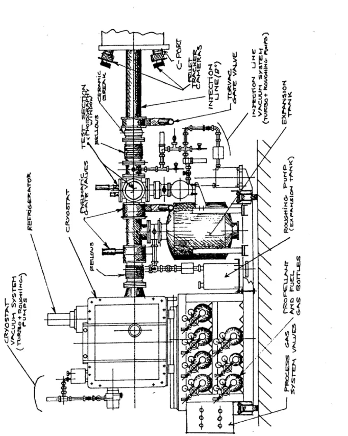
Pellets leaving the barrels pass through the injection line prior to entering the
tokamak . The injection line functions as an independent vacuum system which is separated by a gate valve from that of the torus. Two time of flight laser -photodiode
gates located in the injection line are used to measure pellet velocity . A series of baffles and pellet "guide tubes" serve to direct propellant gas away from the tokamak and into
the expansion tank where it can be pumped away. Forward of the guide tubes and
photo-diode gates is a test cell with two windows to facilitate pellet photography .The cell is
equipped with a retractable target plate to which is attached a microphone for detecting
pellet impacts.
The injection line, cryostat vacuum system, fuel and propellant systems contain over 100 valves. Those which are required to freeze and fire pellets are operated by
programmable logic controllers (PLC) with a menu driven P.C. user interface. These systems allow for both the automatic control of the pellet freezing process and the
monitoring of injector pressures and temperatures.
Firing of the propellant valves and high speed data acquisitions from the pellet
diagnostics are made by CAMAC system timing and digitization modules. Data storage and manipulation is via MDSplus software run on a network of interconnected digital workstations. Shot data from the injector and other diagnostics are stored in a hierarchical data structure or 'tree' which can be accessed by the MDSplus software for analysis of
I
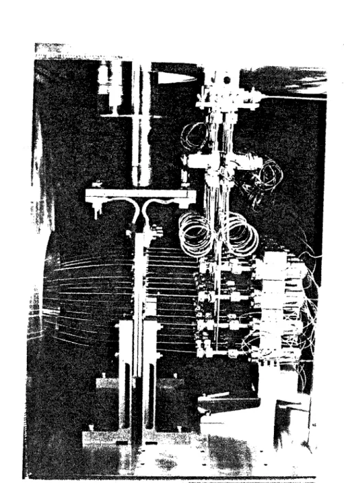
*1 u ... £0 'J) 0, 10 W WFig. 2.3.4: The Injector, showing cryostat and injection line to C-port. /7
2.4
Barrel and Thermal Systems Design
The pellet injector barrels are arranged in a 5 x 4 rectangular grid with an inter barrel spacing of 2 inches. The minimum possible spacing is dictated by the dimension necessary for the propellant valves at the aft ends of the barrels. The modular , "building block" design of these valves minimizes the space needed per valve. Gun barrels are made of type 304 stainless steel. The tubing used is manufactured for use in hypodermic needles and has a wall thickness and outside diametric tolerance of .001 and .0005 inches respectively. Close tolerances are desirable to minimize gas blow-by of the pellet. The barrels are approximately 73 cm in length and have a reflex curve ( see fig. 2.4.1). The curve reduces the forward inter-barrel spacing to one inch so that the 4 x 5 array of barrels may fit within an 8 inch injector line. The top two rows of 5 barrels are 13 gauge with nominal outside diameters of 2.4 millimeters . The lower rows of barrels are 15 and 17 gauge with diameters of 1.8 and 1.5 mm. Minimum burst pressure for all barrels is over 7500 psi.
Heat conduction to the pellet freezing zone is made through a copper disk silver brazed to the barrel. A cross sectional view of this geometry is given in fig. 2.4.2. The disks are made of high purity OFHC copper for good conductivity (RRR 50) and are
one inch in outside diameter. Disk thickness is used to control the pellet length and is
.060 in. for the top row of 13 gauge barrels and .040 in. for the 13 , 15 and 17 gauge
barrels, (rows 2, 3 and 4).. Initial attempts at brazing the conduction disks to the barrels employed a vacuum furnace with a tungsten filament heater to melt a small loop of silver braze wire into the disk-barrel joint. Control of the flowing solder proved to be more difficult than anticipated with much of the solder flowing away from the joint and wicking onto the surface of the copper disks. The method also produced gaps in the barrel to disk joint, the uniformity of which is critical for efficient heat transfer. A second method involved hand brazing using a gas torch with an argon gas shield. This produced a uniform and continuous braze connection, but it became difficult to later remove the braze fillet without affecting the disk thickness. Removal of the braze fillet is necessary to accurately control the length of the pellet freezing zone. Ultimately, new barrel disks
7'
/
/
K
~ c~A.t~REL ~.U~iN G-~i LV~I~ ~%Z~ r~iNr--~Mc~v~ F*~ /7/
K
Co N ~O CT C'S Is c:~ 00
/K>
)
v-f
I
0 z C L.J 0 C C C I-InFig. 2.4.1: Barrel with copper conduction disc.
z
4
0
<N N K N N. 'N. N N~' N. 'N
'Ni
/ 7 ~-~Mj A4j-* L. ~ FLAN G&MS C-* : -C E9LLET N I' N \N N .\N
N N N N ~±j~H4i~+4
'~ ~ N. NK
/ S)7v r 4 C> 'u fiLLT HT~d NOSFig. 2.4.2: Close up sectional view of barrel conduction disc to barrel cold plate connection.
N.
~±i±4
4H-~I
tH+H~±k*~#.
were cut and machined oversize. After hand brazing, these barrel disk assemblies were then turned in a lathe both to remove the braze fillet and cut the disk to the correct thickness.
The twenty barrels are held in a rectangular array by clamping them to a single 10 x 12 x .5 inch copper "barrel cold plate", using two small, circular bolted flanges for each barrel disk. Thermal contact resistance was reduced by placing felt metal washers between the two parts. The muzzle ends of the barrels pass through a single sealing flange which separates the cryostat vacuum from that of the injection line. The barrels have steel bushings brazed in place where they pass through this sealing flange. o-rings are used to seal between the barrel bushing O.D. and the sealing plate. Forward of the sealing plate, the barrels are straight and are angled towards the injection line central axes so that all barrel lines of sight are aimed to converge at a common point on the plasma centerline. The muzzle of each barrel is held in place with Torlon bushings located in the first laser -photodiode gate. The inside of each barrel therefore communicates to the injection line vacuum, and it is sealed from the cryostat vacuum. Aft of the cold plate, the barrels connect to " T " shaped gas fittings which link each barrel to a propellant and fuel valve. Barrel seals are made with small O-rings sealing on the barrel O.D.. All seals are designed to function despite the slight axial movement which accompanies thermal expansion and contraction of the barrel.
The thermal connection between the barrel cold plate and the refrigerator was initially made with two flexible copper joints which consist of a sandwich of 16 copper plates .012" in. thick The sandwich of plates is L-shaped with solid copper plates brazed to each end. The two flexible joints are parallel and thermally link the barrel cold plate with the refrigerator cold plate which is bolted directly to the refrigerator cold head. Thermal contact resistance between the barrel cold plate, flex joints and refrigerator cold plate was minimized by soldering copper backed felt metal pads to both ends of the flex bus on all contacting surfaces. A felt metal pad is also soldered to the refrigerator cold plate where the bolted connection is made to the cold head in order to reduce the temperature drop across the connection. The barrel cold plate, flexible joints and refrigerator cold plates are all plated with 30-50 micro inches of gold to prevent the formation of copper oxide on mating surfaces. The oxide has low thermal conductivity and increases the contact resistance between components in the thermal chain.
The original thermal configuration , while successful at freezing deuterium, proved incapable of freezing hydrogen. Modifications to the thermal connection between the cold head and the barrel cold plate were made in order to reduce temperatures in the pellet freezing zone to below the freezing point of hydrogen. Heat flow experiments showed the thermal resistance between the barrel freezing zones and the cold head to be dominated by the contact resistance between components . A re-design of the
connection replaced the refrigerator cold plate and flexible joints with a single piece of copper, thereby eliminating one joint. Contact resistance is minimized by replacing the feltmetal pads with highly polished surfaces coated with vacuum grease. A surface finish of 6 micro inches and flatness to within .0001 inches of ideal is required to ensure contact across the entire joint surface. Positive contact pressure is maintained across all joints by using bellville washers in the bolted connections. The thermal system changes proved successful in enabling hydrogen freezing. Discussion of thermal tests and a more detailed rationale behind the design changes to the thermal system components are presented in chapter three.
The barrel cold plate is mounted on the cryostat floor with four L-shaped TORLON legs. The legs have low heat conductivity ( .20 W / m2K @ 50 K ) and a H-shaped cross section for increased stiffness with a minimum cross sectional area. Thermal expansion and contraction of components during cooldown is estimated to be approximately one millimeter. This movement , which was formerly taken by the flexible joints, is permitted on the redesign through the use of undersize, loosely fitting bolts on the connection between the TORLON mounting legs and the cold plate .The decreased contact pressure between the legs and the barrel cold plate further reduces the refrigerator heat load. The arrangement of the cryostat internal components for both configurations is shown in figures 3.1.1 and 3.1.3.
2.5
Closed Cycle Refrigeration
Apart from the liquid helium ressuply and cell access issue, The use of a closed cycle refrigeration system may be justified from a purely economic standpoint.. Typically, an injector may use 100 liters of liquid helium per day of operation. At a cost
ED LD
0
(D
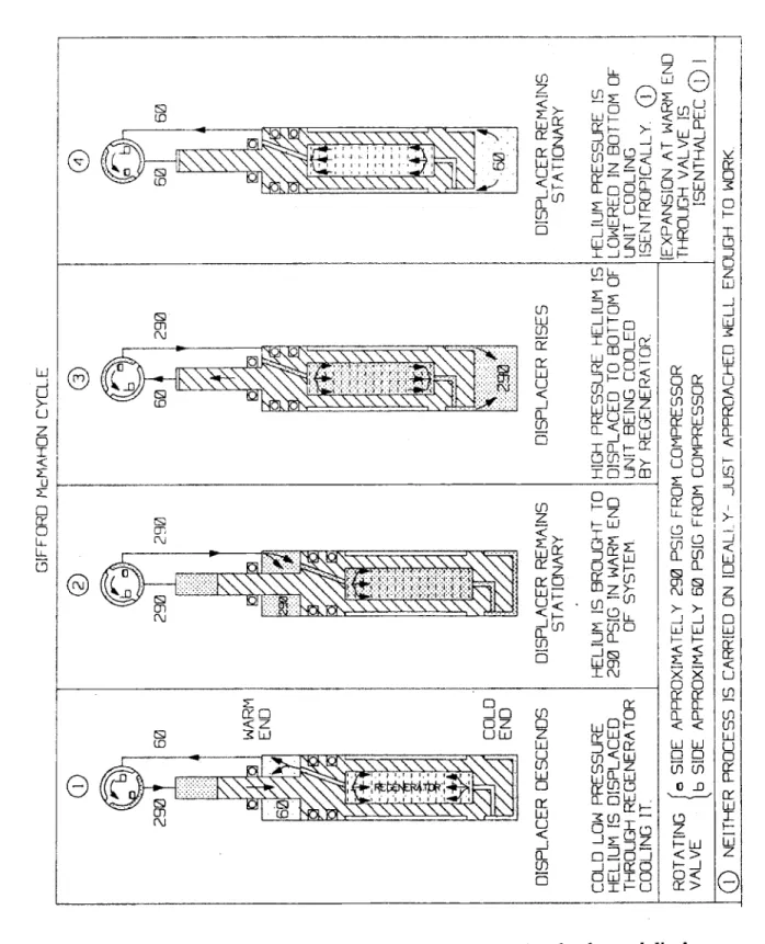
< z x0 U< -J O 0-0 0 -LL LiZ< <HL riD - > < 00 Ln I -0 Lii 0h0 TC± fo U 1 U L0 0n _jSJLL CL C0DTL 00 ... io J CO C Lu 0 :Kc <0 uJ o L cT20 0~ a~~ j 0 m CD CO Li ::)U QiFig. 2.5.1: The Gifford-McMahon cycle showing associated valve and displacer positions (courtesy of Cryomech inc.).
Li -j U U z 0 U C U-0 cy 00 00 0z cl> LDLLL En C 6- L S G aCC CC CO z HLJ 0 <
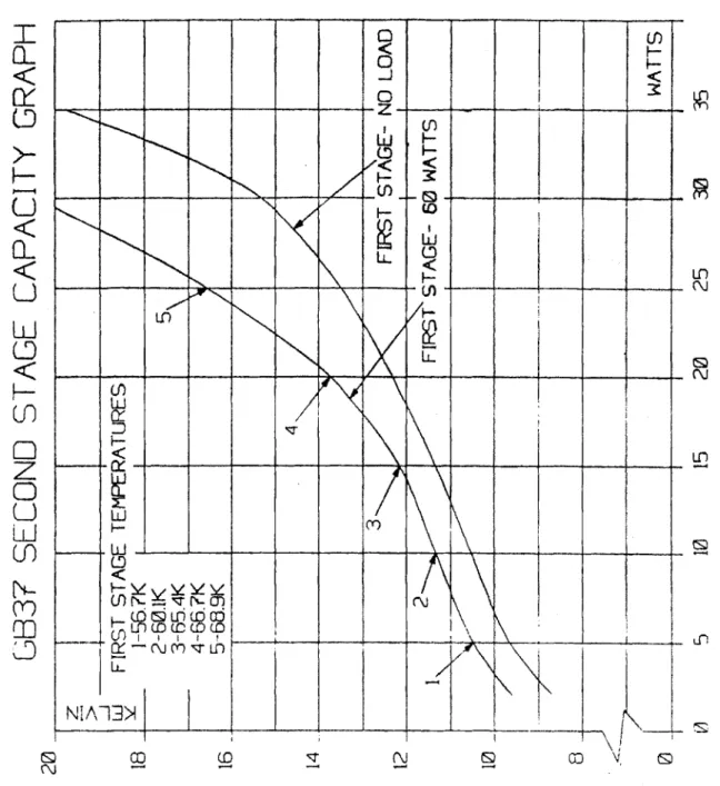
of four and one half dollars per liter and 50 days of operation per year, annual helium expenses may exceed $20,000. For these reasons, the C-Mod injector uses a closed cycle helium refrigerator to freeze the fuel gas. The use of the closed cycle refrigerator is justified not only by the reduced access requirements but also by economics. The cost of the Cryomech GB-37 unit used was $35,000 ( 1989 $ ) and may be amortized over a period of less than two years when considering the liquid helium expense estimate given above.
With no heat load, the minimum cold head temperature for the GB-37 is 8.5 K. The cold head temperature increases with increased heat load and it is a critical parameter in the pellet freezing process. The minimum cold head temperature as a function of heat load for the refrigerator is given in fig. 2.5.2.
The refrigerator consists of 3 basic elements (See fig. 2.5.3 refrigerator cross section) . A synchronous motor driven "plate" valve (2) the first and second stage
"displacers" or pistons (21) and (7) and the first and second stage regenerators (22) and
(25). In operation, the refrigerator is fed a flow of compressed helium at 290 psi from a
separate compressor package. The valve is rotated by the synchronous electric motor at
72 RPM and permits helium to flow at nearly constant pressure down through the first
and second stage regenerators. The regenerator cools the helium which simultaneously lifts both the first and second stage displacers upwards in an isobaric process. Next, the valve plate rotates linking the top of the regenerator to the low pressure compressor return line. The high pressure helium then expands through the regenerator, dropping in pressure and temperature and removing heat from both the regenerator beds and the refrigerator cold head. Helium from the first stage displacer flows only through the first stage regenerator, but helium from the second stage displacers flows through both the second and first stage regenerators
The regenerators consist of cylindrical tubes filled with heat conductive shot. The beds are cooled by expanding the helium and in turn, remove heat from the incoming high pressure helium, so that gas entering the displacer is only a few degrees warmer than the low pressure expanded helium. As a final step in the cycle, the rotating valve plate connects the top of the displacers to a high pressure supply forcing the displacers down and into position to move upwards and accept the next charge of high pressure helium.
11 C -J
CA-T
a-CD
a-Li
LD
-ED
0
LiJLD
CD LO U!) X ___I
.j7T1
- - + 4 -A- - ~-4~-4- + -~ - + -4---4-0! UL LIL CD U )i Of IT LO NIA~G)2.
/ N /r \ I - IFig. 2.5.2: The GB37 minimum cold head temperature as a function of heat load.
Tn~VT~
nUIn
~/1
A
K
-<h-. 4--
SECT~Fig 2.5.3: The Cryomech GB37 refrigerator (courtesy of Cryomech inc.).
The Gifford McMahon (G-M) cycle and the corresponding displacer positions are shown schematically in fig. 2.5.1
The refrigerator is mounted on top of the cryostat on an O-ring sealed circular flange. The refrigerator cold head is internal to the cryostat vacuum system preventing freezing of both air and water on exposed cold surfaces. Two flexible, stainless steel hoses are used to connect the refrigerator to the compressor package. The high pressure line carries helium at about 280 psi and the low pressure return line at 60 psi. The lines are fitted with self sealing aeroquip couplings at each end to prevent contaminates from entering the system during hookup or removal of the lines.
The compressor unit consists of an electrically driven helium compressor and water cooled heat exchanger. Helium leaving the compressor is passed through air /oil strainers, agglomerators and coalescers to remove oil entrained in the helium. A charcoal adsorber bed removes any remaining contaminants from the helium flow. High purity of the helium is required to prevent impurities from condensing and accumulating in the refrigerator. The compressor displays the inlet and outlet pressures and has provisions for helium recharge. A thermal shutoff switch protects the compressor should overheating occur. Water flow to the heat exchanger is monitored through two flowmeters . Power to the compressor is interrupted if the cooling water flow rate drops below a preset value.
2.6 Propellant and Fuel Valves
Each of the twenty injector barrels is connected to both a propellant and a fuel valve. The propellant valve is a high pressure, solenoid driven valve capable of opening and closing in less than one millisecond. Fast opening and closing of the propellant valve is needed to ensure that barrel pressure rises to a maximum before the pellet has left the barrel ( 100's of y seconds) and closes fast enough to minimize the propellant gas load behind the pellet.
The twenty fueling valves are simultaneously cycled during the pellet freezing process. Each barrel requires its own valve, not to control freezing in individual barrels, but to isolate other barrels from the pressure pulses generated when propellant valves fire. Valve orientation is such that propellant gas pressures acts to close the valve.
The C-Mod injector propellant valves design is essentially identical to that developed at the Oak Ridge National Laboratory by the pellet fueling group [45]. Externally , however, changes were made to permit closer valve spacing. The changes were needed because the C-Mod injector was designed with twenty barrels. It was therefore important to reduce the inter-barrel spacing, both to minimize the cryostat size and to reduce the amount of curvature needed to converge the barrel ends into the injector line. Inter-barrel separation is governed by the space needed for propellant valves. Staggering or remote placement of the propellant valves from the barrel cold plate is not desirable because the applied pressure pulse from the valves are flattened in time, prior to reaching the pellet and barrel. To minimize the inter-barrel spacing, the propellant valve housing block was configured to bolt together in "stacks" of four. The valve housings seal together in vertical groups of four forming a single supply manifold for all four valves. Five stacks of four valves are mounted onto a single aluminum manifold to form a 4 x 5 rectangular array.
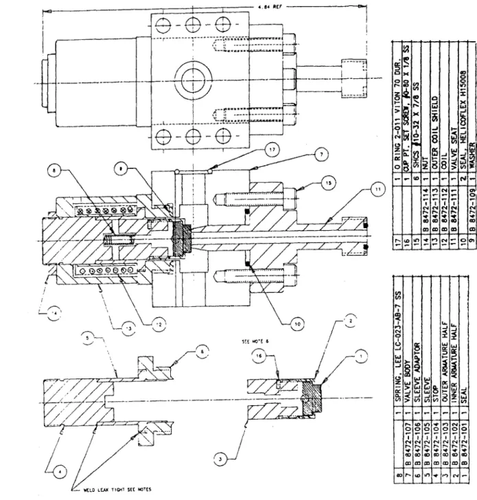
The valve internal design is shown in fig. 2.6.1 and consists of a cylindrical plunger with a Teflon seal insert. (Parts 1,2,3) which is held by gas pressure against the valve seat. (Part 11) The plunger forms part of a magnetic circuit and is drawn off the
{
'.- ~3
'EM NOE TIGH SE
i
r1o
Fig. 2.6.1: The propellant valve with sectional view showing internal parts.
-4 0 0 N r~. 4-0 0 0 U., 0 N 4. 0 0 'A, 0 N 0 0 '~2 4, 04 REF
----
---
--
--- -17 ... ---a
E-i
6valve seat when the drive solenoid is energized. The valves are opened impulsively with the majority of plunger travel governed by spring and inertial forces after an initial magnetic "kick" from the drive solenoid.
Propellant valves were manufactured using numerically controlled machines at
STC Incorporated. This ensures a high degree of uniformity in the machined valve
components and reduces performance variations between valves . Valve components
4,5, and 6 of figure 2.6.1 were electron beam welded to form a gas tight assembly
within which the valve plunger or armature moves. The Teflon seal , (9) between this assembly and the valve body was found to leak and was replaced with an 0 ring seal as were all Helicoflex seals indicated in the design. All valves were leak tested using a helium leak detector in the "sniffer" mode to check for high pressure leaks past the valve seat and from the valve body. Any leaks were corrected by polishing the valve seat sealing surfaces.
The propellant valves are driven by MOSFET transistor switched capacitor
(2900 11 F ). The power transistors are triggered by signals from the CAMAC timing
modules through an opto-coupler for electrical isolation. Each board has an independent
DC power supply linked through isolation transformers to a single variable AC power
supply thus preventing crosstalk between driver boards. Each board has current and voltage monitoring resistors for diagnosing the driver circuits and valves. The boards are mounted in groups of ten in two rack mounted chassis.
Propellant valves were tested by determining the minimum capacitor voltage necessary to just open the valve for fixed pulse lengths and propellant supply pressures. The results indicate that for shorter pulse lengths greater driver voltages are required for valve operation, regardless of supply pressure. The intention is to operate the valves with the shortest pulse length needed for reliable valve operation. Valve operation in this mode minimizes the propellant gas load from the injector to the Tokamak vacuum vessel. Valves are typically operated with pulse lengths of 950 microseconds at 80 volts.
Fuel valves are located in two rows of ten above and behind the barrel cold plate. The valves are mounted to a rectangular, aluminum manifold block which supports and
supplies fuel to all 20 valves. The valves are commercially available Skinner solenoid valves and are mounted with the high pressure side of the valve towards the barrels. With
this orientation , firing pressures force the valves closed preventing propellant gas leaks
into the fuel system. The valves are held open for several minutes during the pellet freezing process. Since the fuel valves operate in a vacuum and dissipate heat primarily
by conduction and radiation , the minimum DC valve operating voltage is used to prevent valve overheating. Temperatures on the valves are monitored by thermocouples. Initial operation of the injector showed that the fueling valves were not cooling sufficiently between batches of pellets but were instead "ratcheting" up to high temperatures. The valves require approximately six volts to open initially but only three to keep open. By operating the valves with a circuit which drops the supply voltage by fifty percent after initial switching, valve input power was reduced by 75%
, thereby eliminating overheating.
2.7 Process Gas System
The propellant and fuel systems together form the "process gas system", the majority of which is located on the aft end of the injector carriage. Hydrogen, helium and neon are selectable as propellant gases and are stored in high pressure gas cylinders on the injector carriage. A schematic of this system is presented in fig. 2.7.1.
Each gas bottle has a manual tank shutoff valve, a high pressure regulator (100-2000 psi) and a line valve. Flex lines connect the propellant gas tanks to the process gas system. Each gas line has pressure sensors, solenoid valves and a check valve to isolate each bottle. Gas lines from each bottle connect through solenoid valves to a single propellant feed line fitted with a flow restricting needle valve (N2). A 1/4 inch flex line carries the propellant gas from the process gas system to the cryostat . Internal to the cryostat, a 1/8 inch stainless steel line carries gas to the propellant valve manifold block. Propellant gasses are selected by venting and purging the propellant lines, manually setting the regulator pressure, and opening the solenoid valve (S4, S5 or S6) to the selected gas by PLC control.
0) I I 0 -~ I C I I 0 a () V I 0 N a N
4
E U-,D 0 C-~ C' C' CC4 x x Cn V) z *) > CC rNFig 2.7.1: Schematic of the process gas system
E (-n >0 (U0 0 CL x C z
The fuel system gases are hydrogen, deuterium and neon . Like the propellant system, each gas bottle has a low pressure regulator (20 psi) and two shutoff valves. Flex lines link each bottle to PLC controlled solenoid valves (Si, S2, S3) and isolation check valves . A single line connects all three gases through the needle valve (NI) to a
one liter volume plenum. The plenum is provided with a burst disk, relief valve and pressure sensor (P8). After gas changeovers, this plenum can be purged and evacuated
by roughing pump 2 through valve (PN 10). The fuel system is operated by setting the
regulator pressure on the selected gas bottle to slightly above atmospheric and opening the solenoid valve to the gas plenum. Plenum fill pressure is pre-set, so that when the correct level is measured at (P8), the PLC closes the feed valve ( S1,S2,or S3). Pellet freezing is initiated by then opening the twenty fueling valves inside the cryostat and bleeding the fuel gas from the plenum, through the barrels and into the bellows volume between the barrel muzzle sealing flange and the 1st injection line gate valve (PN7).
Line pressures is measured by diaphragm strain gauge sensors which are supplied with regulated DC. voltage. Output voltages are amplified , measured by the PLC and converted to the correct units for screen display.
All process gas components and lines are interconnected with VCO type O-ring
fittings. These seals were found to work reliably and , unlike Swagelock seals, are easy to disconnect and later reseal. Propellant lines are made of 1/8 inch stainless steel tube. Fuel lines were initially 1/8 inch OD. but were later changed to 1/4 inch to facilitate vacuum pumping of the lines.
2.8 Injector Vacuum Systems
The injector vacuum system is functionally divided into the cryostat and injector line vacuum systems forming two independent parts. The overall layout of this system is given in figure 2.8.1. The cryostat vacuum system consists of a Balzers TPN 170 turbomolecular pump backed by a Leybold rotary vane roughing pump . A bypass line at the base of TP1 connects to the larger roughing pump RP2 to speed up initial pump down. The cryostat itself is a rectangular box, approximately 22 inches wide, 33 inches