Publisher’s version / Version de l'éditeur:
Canadian Agricultural Engineering, 21, 2, pp. 69-77, 1979-12
READ THESE TERMS AND CONDITIONS CAREFULLY BEFORE USING THIS WEBSITE. https://nrc-publications.canada.ca/eng/copyright
Vous avez des questions? Nous pouvons vous aider. Pour communiquer directement avec un auteur, consultez la première page de la revue dans laquelle son article a été publié afin de trouver ses coordonnées. Si vous n’arrivez pas à les repérer, communiquez avec nous à [email protected].
Questions? Contact the NRC Publications Archive team at
[email protected]. If you wish to email the authors directly, please see the first page of the publication for their contact information.
NRC Publications Archive
Archives des publications du CNRC
This publication could be one of several versions: author’s original, accepted manuscript or the publisher’s version. / La version de cette publication peut être l’une des suivantes : la version prépublication de l’auteur, la version acceptée du manuscrit ou la version de l’éditeur.
Access and use of this website and the material on it are subject to the Terms and Conditions set forth at
Problems with concrete tower silos
Bozozuk, M.
https://publications-cnrc.canada.ca/fra/droits
L’accès à ce site Web et l’utilisation de son contenu sont assujettis aux conditions présentées dans le site
LISEZ CES CONDITIONS ATTENTIVEMENT AVANT D’UTILISER CE SITE WEB.
NRC Publications Record / Notice d'Archives des publications de CNRC:
https://nrc-publications.canada.ca/eng/view/object/?id=1a4e3c0a-2b11-479c-adf3-63519fe219d0
https://publications-cnrc.canada.ca/fra/voir/objet/?id=1a4e3c0a-2b11-479c-adf3-63519fe219d0
National Research Council
of
Canada
Conseil national de recherches
du
Canada
PROBLEMS WITH CONCRETE TOWER SILOS
by
M. Bozozuk
Reprinted from
Canadian Agricultural Engineering
Vol. 21, No.
2, December 1979
9 PP-
DBR Paper No. 877
Division of Building Research
SOMMAIRE
Chaque annCe, plusieurs milliers de tours d'ensilage sont construites a u Canada et la plupart d'entre elles fonctionnent t r t s bien. RCcemment, des probltmes sont survenus dans les constructions plus grandes concernant la capacitt portante des sols, les fondations inadtquates ou ma1 c o n p e s , les jus d'ensilage, la dettrioration d u btton avec le temps, le relgchement des cerclages d'acier, la repartition non uniforme
a
I'ensilage et les surchages entrainant des dtformations et des contraintes excessives aux parois. L'auteur dCcrit ces probltmes dans le cadre d e
6
cas concrets.PROBLEMS WITH CONCRETE TOWER SILOS
M.
Bozozuk
Georechnical Section, Division of Building Research, Na~ional Research Council of Canada, OIIawa, Onrario K I A OR6 Received 25 February 1979
M. Bozozuk. 1979. Problems with concrete tower silos. Can. Agric. Eng. 21: 69-77.
Several thousand tower silos are erected on Canadian farms each year, and for the most part perform very well. Recently some problems with larger structures have appeared in connection with bearing capacity of the soils, inadequate and underdesigned foundations, silage juices, deterioration of concrete with time, relaxation of steel hoops, non-uniform placement of silage, and overloading resulting in deformation and overstressing of silo walls. These problems are discussed in the six selected case histories presented in this paper.
INTRODUCTION
Over the past 10 yr, a n average of nearly 1500 concrete stave and cast-in-place concrete tower silos were constructed annually f o r the agricultural industry in Ontario. In Quebec the number constructed was a b o u t t h i e e q u a r t e r s of that in Ontario. T h e number of steel silos built is unknown, but it is reasonable t o assume that over 3000 tower silos of all types have been constructed annually for the past 10 yr in this country. If surveyed carefully, many of these silos will show some differential settlement o r tilting which goes unnoticed a s there is n o interference with t h e farmers' operations and use of the structures. Considering the large numbers constructed, it is a tribute t o the silo construction industry that s o many structures behave s o well.
In a small percentage of cases, however, serious problems have occurred. In weak compressible clay areas, tall silos have overturned when the applied loads exceeded the bearing capacity of the foundation soils (Bozozuk 1972, 1977; Eden a n d Bozozuk 1962). Others have tilted o r deformed t o such a n extent that they c a n n o t b e used, and sometimes become a hazard t o neighboring structures a n d t o livestock. This paper presents a number of selected case histories t o identify many of the serious problems encountered recently with tower silos. During the investigations, t h e farmers' descriptions were used t o describe t h e
.
-
condition of the silage, a s measurements of moisture content were not made when the silos were filled o r when the studies were made. All silos were filled usingdistributors.RICHMOND
In August 1975, a concrete tower silo 9.14 m in diameter, 32.3 m high, was constructed o n overconsolidated marine deposits of the Champlain Sea. T h e cylindrical concrete wall was 152 m m thick a n d was reinforced circumferentially with steel bars embedded in the concrete during construction. T h e foundation was cast-in- place non-reinforced concrete in the form of a ring 610 m m thick, with inside and outside diameters of 7.62 m and 11.89 m, respectively. Drains were provided in the base of the silo wall t o control the silage juices.
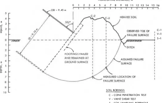
Figure 1. Bearing capacity failure of soil for 9.14-111 diameter, 32.3-111 high concrete silo at Richmond, 30 Sept. 1975. HORIZONTAL DISTANCE, m 0 1 2 3 4 5 6 7 8 9 10 11 1 2 1 3 1 4 1 5 1 6 I I I I I I ~ I I I I I I I ~ ~ OBSUIVED TOE OF ASSUMED FAILURE I I FAILURE SURFACE SOIL BORINGS C - C O N E PENETRATION TEST V -VANE SHEAR TEST S - SOIL SAMPLING BOREHOLE
Figure 2. Richmond silo after failure showing silo heave, location of sliding surface and location of soil borings.
The Failure explosive force o n impact blew the roof off O n 30 Sept. when the silo was being the silo a n d overturned a truck parked o n filled, it overturned a t a load of 1800 tonnes the other side of the new barn. Neighbours (Fig. 1). T h e combined mass of the structure 0.5 k m away felt the ground vibrationsat the a n d its contents a t the time was 2260 tonnes. time of impact. Fortunately the livestock In falling, it destroyed a large part of a new were evacuated from the barn just prior t o barn, a n d damaged part of a n old one; the the failure.
When the silo was being filled, it was observed that the concrete footing had cracked. As filling continued, the cracks widened, the toes of the cracked sections heaved, and the silo started tilting, at which time filling was suspended. Unfortunately the contact area under the foundation was reduced, and the silo overturned.
The position of the silo foundation after failure is shown in Fig. 2. The intact part of the silo was inclined 53" from the vertical. As the base rotated, part of the silo tubesank 6 rn, whereas the opposite edge heaved 1.5 m. The soil heaved for a distance of 9 m and formed a mound about 4.5 m high. Soil Investigation
The soils investigation consisted of sampling for laboratory analysis, in situ vane shear strength tests for determining the bearing capacity of the soil, and in situ cone penetration tests to locate the failure surface. The locations of these borings are shown in Fig. 2.
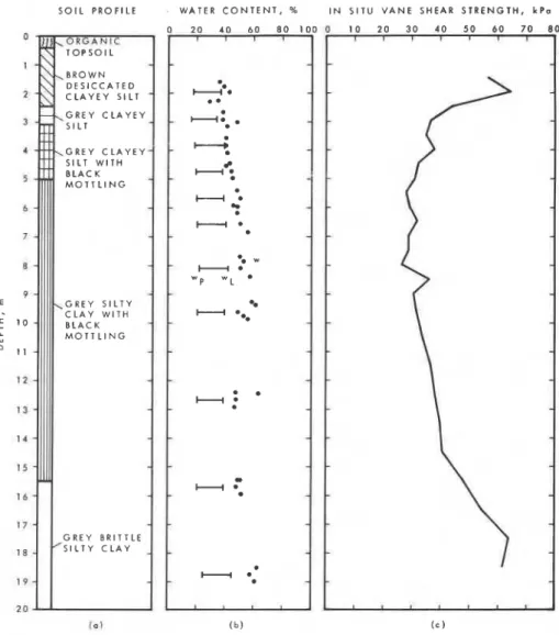
The soil profile is shown in Fig. 3a. Below the topsoil, a hard desiccated brown clayey silt formation extended to a depth of 2.4 m, the depth where the groundwater table was encountered. The underlying material was a softer gray clayey silt with traces of black mottling at 3.1 m. At 5.0 m the soil changed to gray silty clay with black mottling. This formation extended to a depth of 15.5 m. The last 4.5 rn of the borehole contained brittle gray silty clay with no mottling.
The classification tests (Fig. 3b) indicated a plasticity index of 20% and a liquid limit of 40% for the soil profile. (The classification test results are indicators of the engineering behavior of the soils (Lambe 1951)). At 2 m the water content of the soil was about equal to the liquid limits, but it gradually increased with depth to 60% a t 9 rn indicating that the clays were extremely sensitive. Grain size analysis showed 37% clay and 63% silt size particles at 2 m, changing almost linearly with depth to 58% clay and 42% silt at 16 rn. The in situ shear strength of the soil measured with the NGI vane (Andresen and Bjerrum 1956) is shown in Fig. 3c. The strength was quite high in the desiccated crust, reaching 65 kPa. It reduced rapidly to 45 kPa at the base of this formation and continued to decrease to a minimum of 31 kPa at 5 m. The strength was about constant for the next 3 m, then increased with depth to the bottom of the boring. The average shear strength below the footing to a depth of two-thirds the outside diameter of the ring foundation was 36.5 kPa.
T h e cone penetration tests were conducted through the heaved soil to locate the failure surface. As shown in Fig. 2, the soundings and the profile of the heaved soil delineated a failure surface which compared well with the theoretical circle of failure. Bearing Capacity
The ultimate bearing capacity for the soil was 241 kPa, calculated from qU = c Nc + P (Skempton 1951) and the average in situ
S O I L P R O F I L E WATER C O N T E N T , % I N S I T U V A N E SHEAR S T R E N G T H , k P a D E S I C C A T E D C L A Y E Y S I L T G R E Y C L A Y E Y G R E Y C L A Y E Y M O T T L I N G G R E Y S I L T Y C L A Y W I T H M O T T L I N G G R E Y BRITTLE S I L T Y C L A Y ( 0 1 ( b ) ( c )
Figure 3. Engineering properties of soil at Richmond.
vane shear strength. Assuming a full contact area of 1 11.0 m2 for the foundation, the factor of safety against failure was 1.2. Because the concrete footing cracked before failure occurred, the actual factor of safety could not be determined. If the contact area was reduced to 70.1 m2, the cross-sectional area of the tower, the factor of safety would be 0.8. A value of 1.0 would have been obtained if the effective contact area was 91 m2, which was a realistic contact area at the time of failure.
Discussion
It is difficult to understand why a structure as high as a 10-storey building should be constructed on clay soils without a soils investigation. Furthermore, it is equally difficult t o understand why foundations for such an immense structure should be constructed without steel reinforcing. The evidence for the cause of the failure points to inadequate foundations. When the ring foundation cracked during loading, the contact area was reduced and failure occurred when the bearing capacity of the soil was exceeded.
The failure at this stage of loading may
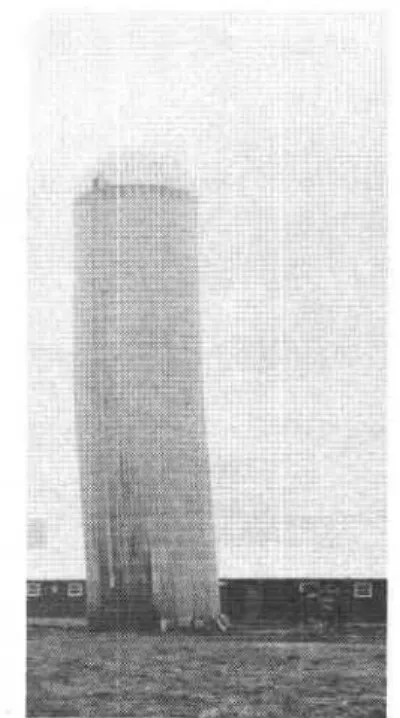
Figure 4. Casselman silo, 6.10 m diameter,
21.34 m high, leaning 765 mm from the vertical, 31 Jan. 1978.
S O I L PROFILE SHEAR S T R E N G T H , k P o D I M E N S I O N S OF CONCRETE R I N G F O U N D A T I O N S 0 BROWN F I N E SILTY S A N D ' 2 z
-=-
4 6 LAYERED GREY SILTY C L A Y B HARD LAYER 1 a 12 VERY HARD 1 4 LAYER-
14-
-
18-
-
20-
S I L O N O . I , ( O D 4 . 8 8 m , H T . 1 8 . 2 9 m ) R l N G F O U N D A T I O N O D 6 . 10 m$
S I L O N O . 2 . ( O D 6 . 1 0 m . H T . 21.34 m ).
:
.
,
* R l N G F O U N D A T I O N S I L O N O . 3 , ( O D 4 . 2 7 m . H T . 1 5 . 2 m ) R l N G F O U N D A T I O N-
:- . . . . I ..- ..v.';:=,:,.
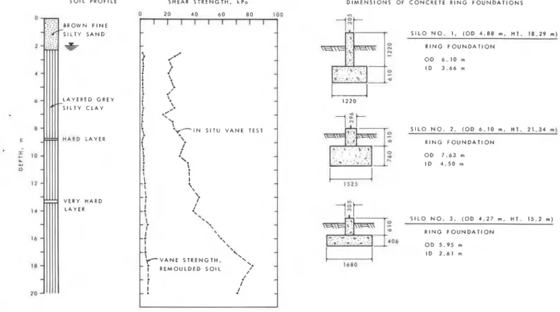
:. O D 5 . 9 5 mFigure 5. Soil profile, in situ vane shear strength and dimensions of concrete foundations for silos a t Casselman.
have been a blessing in disguise. If the foundation had remained intact, the silo might have been filled t o capacity. Because of the very low factor of safety, however, a much more catastrophic failure could have occurred. There is little doubt that even if the concrete foundation had been reinforced, it was still inadequate for the structure and the soils at the site.
CASSELMAN
T h r e e concrete stave silos were
'
constructed in a row on a marine clay plain about 40 km east of Ottawa. Number 1 was a 4.88-111 diameter silo, constructed 6 yr ago to
..
a height of 12.2 m. In 1977 it was raised to a height of 18.29 m. Number 2 was a 6.10-111 diameter silo, 21.34 m high, constructed in 1975. Number 3 was 4.27 rn in diameter, 15.2 m high, erected in 1977, and was empty. Number 1 performed well, even after its height was raised in 1977. Number 2 performed well but was never filled until 1977 when it was filled to capacity for the first time with wet grass silage t o a height of 16 m, and topped with wet corn silage. Following this loading it started t o lean drastically as shown in Fig. 4.The Problem
Silo No. 2 had settled vertically about 20 cm and was tilting 765 mm (2.05') from the vertical, whereas Nos. I and 3 were performing satisfactorily. To determine
Figure 6. Foresters Falls silo, 6.10 m diameter, 21.34 m high, leaning 1213 m m from the vertical, 3 Nov. 1978.
what caused the settlement and tilting, a detailed inspection of the foundation was carried out.
The ring foundations for Nos. I and 3 were nonreinforced cast-in-place concrete with the dimensions given in Fig. 5. Drains were included in No. 1 to handle the silage juices.
The ring foundation for No. 2 was similar
in design but larger (Fig. 5). Steel reinforcing was not used and drains were not installed. This foundation was constructed by the owner, who excavated a circular trench to
the required dimensions using a backhoe.
When the concrete was placed water was added to it to encourage the concrete mix t o "flow" around the trench easily. It was not possible t o see whether the foundation was cracked because it was buried with backfill. Soil Investigation
Soil borings and in situ vane tests were performed in May 1978. Although samples were not taken for testing, the borings indicated 2.3 m of fine brown silty sand over layered gray silty clay (Fig. 5). The groundwater table was at a depth of 2 m.
The in situ vane shear strength (Fig. 5)
Figure 7a. Effects of structural distortion on silo: Overlapping bulge Figure 7b. Effects of structural distortion on silo: Horizontal cracks in
of roof due to distortion of stave. concrete staves.
Figure 7c. Effects of structural distortion on silo: Diagonal cracks Figure 7d. Effects of structural distortion on silo: Vertical splitting
in staves. and spalling of staves.
was relatively constant a t a b o u t 23 k P a t o a depth of 7.5 m. It then increased with depth t o 67 k P a a t 17 m. The average shear strength of the soil below the footing to a depth equal t o two-thirds of the outside diameter of the ring foundation was 25.0 kPa.
Bearing Capacity
The ultimate bearing capacity of the soil based o n the average in situ vane shear strength (Skempton 1951) was 165 kPa. When loaded t o capacity the factor of safety against a bearing capacity failure for silos No. 1 and No. 2 was 1.6and 1.3, respectively.
Discussion
This case record illustrates the "trap" many silo builders and farmers fall into. Silo No. I performed very well when it was 12.2 m high. It continued to perform well even after its height was raised t o 18.3 m in 1977. The fact that the foundation had drains t o control the silage juices probably accounted for its good performance even though the factor of safety was 1.6 when the height was 18.3 m. This good performance was p r o b a b l y t h e basic r e a s o n f o r t h e
construction of silo No. 2 t o a height of 21.3 m without a soils investigation. When it was erected in 1975 it performed well for a couple of years because it was never filled. In fact, in 1975 and 1976 the maximum height of silage in No. 2 was about 18 m, a n d this accounted for its good performance. In 1977, however, it was filled t o capacity for the first time. The silo settled vertically and started to tilt. The estimated factor of safety from the soils analysis was 1.3, which is unacceptable for good engineering design. Eliminating the drains from the foundation probably reduced the factor of safety even more because the silage juices started seeping out from under the foundation. Considering all these facts, it is fortunate that the structure and its foundation did not overturn. F o r this type and size of foundation the limiting height of a stave silo on this soil would be about 18 m.
FORESTERS FALLS
In 1975, a concrete stave silo 6.10 m in diameter, 21.34 m high, was erected for corn silage o n a marine clay plain south of the Ottawa River a b o u t 120 k m west of Ottawa.
A second silo, a cast-in-place concrete structure, 5.49 m in diameter, 18.29 m high, was erected adjacent t o it for haylage in 1978. When the silos were filled in 1978, the cast-in-place structure behaved well, but the larger stave silo bulged and started leaning,
-
and threatened t o fall o n the neighboring-
barn (Fig. 6). This was the first sign of any trouble since the silo had been built.Site Investigation
On 3 Nov. 1978, measurements o n the silo showed that it was leaning 1178 m m (3.16") f r o m the vertical in a direction away from the concrete silo and towards the barn. The spherical roof had flattened o n two sides and bulged over the walls of the silo o n the other two sides by about 20 cm (Fig. 7a) because the top part of the silo had deformed from a circle t o a n ellipse. Many of the concrete staves had cracked. These cracks were horizontal (Fig. 7b), diagonal (Fig. 7c) and vertical (Fig. 7d). They were caused by the stresses imposed o n the staves as the silo l e a n e d , twisted a n d bulged o n i t s foundation. T w o steel hoops near the base of the silo were also broken. Silage juices were seen bubbling u p through the soil around the
foundation and were leaking through the vertical joints between the staves a t the bottom of the structure.
T h e foundation for the stave silo was a cast-in-place concrete ring, 1.1
-
1.5 m wideand 1.5 - 2.0 m thick, without steel
reinforcing a n d without d r a i n s . T h e excavation for the foundation was made with a backhoe. S o m e large boulders had been thrown into the excavation to reduce the volume of concrete. At the time of the visit there was a differential settlement of the foundation of about 75 mm, the greatest settlement being o n the side of the tilt.
A bedrock controlled stream cut a gulley 5 m deep through the marine clay a b o u t 100 m north of the silos. T h e exposed soil formations were firm gray silty clays. A well d u g o n the property encountered bedrock a t 7.3 m. These observations indicate a well drained competent soil, varying in depth f r o m 5 t o 7 m a t the site.
Danger of Collapse
It was evident that the structure was near collapse. If it fell it would destroy the barn, and the heaved soil from the rotation of the foundation could overturn the new cast-in- place silo located immediately behind it
(Fig. 6). It had t o be unloaded and
dismantled a s quickly a s possible. Attempts t o start t h e unloader located at t h e t o p of the silo were t o n o avail. Because the silo was n o longer circular, the unloader would not work. It could be made to work with constant attention a n d adjustments, but was it safe t o enter the silo? Was the silo still moving; how f a r could it lean before it fell over?
M e a s u r e m e n t s t a k e n l a t e in t h e afternoon of 3 Nov. showed that after 3 h, the tilt had increased by 35 m m t o 1213 m m (3.25') f r o m the vertical. It was not safe t o climb the silo. T o s t o p this rapid movement a n d p e r h a p s prevent t h e silo f r o m overturning, a steel cable was fastened t o one of the steel hoops, 15 m above the base, and anchored t o two large trees 80 m away. A few days later a second cable was attached t o the silo 18 m above the base. T h e movements, a s shown in Fig. 8, were drastically reduced, enabling the owner t o modify the unloader a n d start removing the silage. T h e additional movement measured after the cables were attached was partly d u e t o the upper part of the silo flattening out into a flatter ellipse because the steel cables were anchored t o the flexible steel hoops a t o n e point only.
Discussion
T h e stave silo performed well before 1978 because the maximum height of silage placed in it was a b o u t 18 m. In 1978 it was filled completely and retopped five times. T h e last load was more than 40% greater than in previous years a n d caused the movements of the silo. Although the distributor was used t o place the silage uniformly during filling, the bulge in the structure indicated that a core of high
D A Y S A F T E R L A S T F I L L I N G
Figure 8. Tilt measured on leaning silo at Foresters Falls.
density silage had shifted against the walls of the structure. As the silo leaned, twisted and flattened into a n elliptical shape, cracks appeared in the staves, and two of the steel hoops around the base failed.
T h e soil had adequate bearing capacity t o support the silo filled once t o a height of 18 m. When the 21-m stave silo was retopped five times, it started t o tilt under the increased load, and the foundation settled differentially 75 m m more o n the side of the tilt. A number of factors contributed t o this differential settlement. T h e ring foundation varied in width and thickness, which could cause non-uniform pressures applied t o the soil. It was not known whether the foundation was cracked. When the silage shifted and the structure started t o lean, it also caused a non-uniform loading of the soil, with the pressures being greatest o n the side of the lean. T h e fact that there were n o drains forced the silage juices t o seep o u t from under the foundation and this i n v a r i a b l y w e a k e n e d t h e soil. T h e combination of all these factors, together with the 40% increase in load, contributed t o the differential settlement and the severe tilting of t h e structure. T h e installation of t h e - a r r e s t i n g c a b l e s m o s t p r o b a b l y prevented a c a t a s t r o p h i c failure a n d permitted the silo t o be unloaded.
EMBRUN
T w o concrete stave silos 7.32 m in diameter, 24.38 m high, and a third smaller one were located o n a farm 5 km south of Embrun, 40 k m southeast of Ottawa. During filling with corn silage in 1978 ( a distributor was used), one of the t w o larger structures bulged and tilted f r o m the vertical
Figure 9. Embrun silo, 7.32 m diameter. 24.38 m high, leaning 1475 mm from the vertical, 7 Nov. 1978.
(Fig. 9). As the t w o structures were identical in design, construction a n d loading, a brief investigation was carried out t o find the cause of the problem.
Site Investigation
T h e foundation soils were geologically the same marine clays a s those a t Casselman. T h e soil investigation f o r the structure was performed by the Ontario Ministry of Agriculture and F o o d in the region, a n d t h e
Figure 12. Layered soil formations at Mallorytown silo.
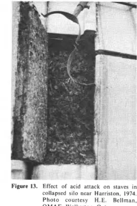
Figure 13. Effect of acid attack on staves in collapsed silo near Harriston, 1974. P h o t o courtesy H.E. Bellman, OMAF, Walkerton, Ont.
The location was in theThousand Islands region where bedrock was near the surface and often covered with competent granular tills. The site was a gently rolling relatively flat plain bordered by rock outcrops. The silo was situated about 25 m south of a rock escarpment near a n old barn. About 0.3 m of granular fill was placed around it to form a road.
Soil Investigation
The soils investigation consisted of three borings for soil samples and in situ vane strength tests. Boring No. 1, 11 m south of the silo, encountered layered silty soils to a depth of 10 m, the maximum depth of the borehole. Number 2, located 6 m west of the silo, also penetrated through layered silty soil but it encountered bedrock at 4.9-m depth. Number 3, which was 5.6 m east of the structure passed through the same silty
soil to a depth of 12.2 m without
encountering bedrock. The groundwater table rose to within 0.13 m of the ground surface in the boreholes.
An examination of the undisturbed soil samples showed that the soils were extremely layered. The results of the soil
tests (Fig. 11) indicated a soil of low plasticity, with an average plasticity index of 16%. The natural water content varied from 21 to 41% and was generally less than the liquid limit of the soil. Based on the grain size analysis and the plasticity index, the soils were mainly finely ground rock flour, 'which behaves as a pure silt.
The in situ shear strength of the soil
measwed with the NGI vane (Fig. I I) varied
with depth from 107 to 135 kPa. Theaverage strength below the foundation to a depth of two-thirds of the outside diameter of the foundation was 120 kPa.
The shear strength measured in the laboratory on the soil samples with the consolidated isotropically undrained triaxial (CIU) test was significantly lower than that measured in situ with the NGI vane, giving an average of 72 kPa for bearing capacity analysis. As these soils were highly layered (Fig. 12) it was very difficult to obtain high quality, undisturbed soil samples for testing. Because of the disturbance from sampling, these laboratory tests underestimated the true strength of the soil.
Bearing Capacity
Based on the average shear strength measured in situ with the vane, the ultimate bearing capacity of the soil (Skempton 195 I) was 790 kPa, givinga factor of safety against
a bearing capacity failure greater than 5.
Using the shear strength measured with the triaxial test, the factor of safety was still more than 3. As the results from the triaxial tests were known to be conservative, the actual factor of safety against a bearing capacity failure was considerably greater than that normally used for good engineering design.
Discussion
According to the owner, every spring, groundwater seeping from the upland made the farm road leading to the barnadjacent to the silo impassable at many places. When seepage stopped the road would dry up and become passable again.
The soils near the silo were very silty and therefore vulnerable t o g r o u n d w a t e r seepage. Local soft spots develop easily in this type of soil, which may consolidate or collapse when loaded. A soft wet spot was detected when the excavation was being prepared for the foundation. It is more than a coincidence that the maximum settlement and tilt occurred over the wet spot.
Placing concrete over loose soil left in the base of the excavation or over uncompacted loose fill can also cause differential settlements if the excavation is too wet and the working conditions unfavorable at the time of construction. After the silo is filled the applied load will compress the loose uncompacted soil, and the foundation will settle non-uniformly causing the silo to lean.
HARRISTON
-
P O R T ELGINIn 1974, a 10 yr-old concrete stave silo
silage is compatible with the size of the silo, thus preventing the formation of silage
, . juices (Daynard et al. 1978).
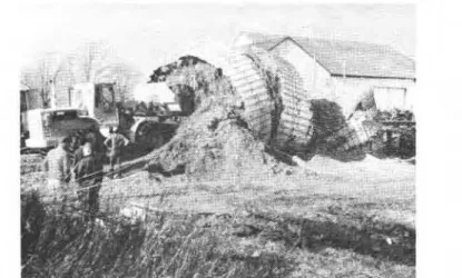
Because it is often impossible to prevent the formation of silage juices, there is a n urgent need to protect the silo walls with special coatings, and t o maintain this protection during the life of the structure. Concrete staves vary from 51 to 64 mm thick, and if deterioration from acid attack occurs, the problem can become critical with respect to loss of structural strength. This ' applies also to cast-in-place concrete silos. The concrete covering the steel reinforcing in the walls of these structures may not be more than the thickness of a concrete stave in front of steel hooping. Since thequality of cast-in-place concrete is often not as high as Figure 14. Port Elgin silo, 7.32 m diameter, 21.34 m high. Collapse due to acid attack on stave sat base factory-produced staves, these structures are of silo, 1978. Photo courtesy H.E. Bellman, OMAF, Walkerton, Ont. equally vulnerable to deterioration from acid attack and to structural collapse in
Figure 15. Port Elgin silo, condition of staves in collapsed silo, showing deterioration from acid attack. Photo courtesy H.E. Bellman, OMAF, Walkerton, Ont.
9.14 m in diameter, 24.38 m high, near Harriston, Ontario, fell over. Visual inspection of the failure indicated that silage acids had attacked the concrete and reduced the effective thickness of some staves at the base of the structure from 51 to about 38 mm (Fig. 13). Structural tests were not performed on the staves, but it is probable that the loss in strength was proportionally greater than the reduction in thickness. The owner reported that some of the staves had buckled and crushed prior to the collapse.
In 1978, a 12-yr-old stave silo 7.32 m in diameter, 21.34 m high, collapsed near Port Elgin about 2 wk after being refilled for the second time (Fig. 14). Visual inspection of the staves near the base of the silo showed that a considerable amount of deterioration had occurred due to chemical attack from silage acids (Fig. 15). The standard 51-mm thick concrete staves were reduced to less than 41 mm thick, and had a n extremely crumbly and porous interior surface. It was practically impossible to locate an unbroken stave in the debris at the base of the silo.
This silo was badly treated early in its life. Silage was placed in a very wet condition, and for about 8 yr hay-crop silage was left in
the bottom 1.2
-
1.5 m of the silo. The interior was not coated at the time of construction or at any later time to protect the walls from acid attack. Consequently the concrete staves deteriorated at such a rate that the silo collapsed from structural failure 12 yr later.Discussion
One of the major problems with concrete silos is the deterioration of concrete walls that are in direct contact with silage juice acids (primarily lactic and acetic) over prolonged periods of time. Juices form when the silage is placed at moisture contents that are too high for the size of the structure and consequently are squeezed out from the ensiling mass. In addition, the pressures forcing the silage acids in contact with the cement walls at the base of a silo increase with increasing height of the silo. These acid juices under pressure etch the concrete walls leading to their deterioration with time. Because the trend over the past decade has been toward larger concrete tower silos, this problem has become very significant. The problem can be controlled in part by ensuring that the moisture content of the
time.
Some research on the suitability of certain coating materials for concrete silos has been done (Jofriet 1977), but more work is required.
SUMMARY AND RECOMMENDATIONS This paper presented six case histories of the performance of tower silos, chosen t o illustrate particular current problems with these structures. These dealt with bearing c a p a c i t y f a i l u r e s ; i n a d e q u a t e a n d unreinforced foundations; omission of drains for silage juices; relaxation of circular steel hoops causing deformation of the silo a n d o v e r s t r e s s i n g o f t h e s t a v e s ; consequences of non-uniform placement of silage during filling; consequences of inadequate site investigations; deterioration of concrete with time; and danger inherent in building larger silos on a site than those dictated by experience, without expert advice.
A review of these problems led to the following recommendations:
1. A soils investigation should be performed by a qualified engineer t o determine t h e allowable bearing capacity of the soil for all large silos. The investigation should include a n engineering appraisal of the site t o detect potential soft spots at the proposed location of the structure. 2. The foundations for tower silos should
be designed for the allowable bearing capacity of the soil. They should be constructed with steel reinforcing and contain drains t o handle the silage juices. A well designed and constructed foundation should support a silo that may be refilled or retopped many times, and resist any eccentric loading that may develop during the lifetime of the structure.
3. The placement of silage during filling should be carefully controlled to eliminate the possibility of creating
high density cores that could shift and ACKNOWLEDGMENTS ASCE. Soil Mech. Found. Div. l(2): 885-902.
deform the structure.
Silo walls should be made of good quality concrete t o resist deterioration from acid attack. Deterioration can be reduced by placing silage at a moisture c o n t e n t n o t g r e a t e r t h a n t h a t recommended for the size of the structure to prevent the formation of silage juices. The interior walls should also be coated for protection from acid attack.
A regular maintenance program should be instituted to: (a) check o n the deterioration of the concrete; (b) check on the tension of the steel hoops which provide the structural strength of the silo.
The Ontario Silo Association, the Ontario Ministry of Agriculture and Food, and the farmers involved kindly supported the study and permitted the information to be published. Special thanks are due to H.E. Bellman, OMAF, Walkerton, Ontario, who provided the statistics and the information on the deterioration of concrete tower silos from acid attack. This paper is a contribution from the Division of Building Research, National Research Council of Canada, and is published with the approval of the Director of the Division.
ANDRESEN, A. and L. BJERRUM. 1956. Vane testing in Norway. ASTM, Spec. Tech. Publ. 193. pp. 54-60.
BOZOZUK, M. 1972. Foundation failure of the Vankleek Hill tower silo. Proc. Spec. Conf. Earth and Earth-Supported Structures,
BOZOZUK, M. 1977. Evaluating sh.dngth tests from foundation failures. Proc. 9th Int. Conf. Soil Mech. Found. Eng. 1: 55-59.
DAYNARD, T.B., R.F. ARNOLD, and H.E. BELLMAN. 1978. Density-pressure seepage relationships of whole-plant corn (Zea mays
L.) silage. Can. Agric. Eng. 20: 45-52. EDEN, W.J. and M. BOZOZUK. 1962.
Foundation failure of a silo o n varved clay. Eng. J . 45(9): 54-57.
JOFRIET, J.C. 1977. Corrosion protection for concrete farmsilos. Can. Agric. Eng. 19(2): 59- 64.
LAMBE, T. W. 1951. Soil testing for engineers. The Massachusetts Institute of Technology, New York, N.Y. John Wiley and Sons. 165 pp. SKEMPTON, A. W. 195 1. The bearing capacity of clays. Proc. Build. Res. Congr., London. pp. 180-189.
This publication is being distributed by the Divisionof Building Research of the National Research Council of Canada. It should not be reproduced in whole or in part without permission of the original publisher. The Division would be glad t o be of assistance in obtaining such permission.
Publications of the Division may be obtained by mailing the appropriate remittance (a Bank, Express, or Post Office Money Order, or a cheque, made payable to the Receiver General of Canada, credit NRC) t o the National Research Council of Canada, Ottawa. K I A 0R6. Stamps are not acceptable. A list of all publications of the Division is available and may be obtained from the Publications Section, Division of Building Research, National Research Council of Canada, Ottawa. K I A OR6.