HAL Id: tel-02152248
https://tel.archives-ouvertes.fr/tel-02152248
Submitted on 11 Jun 2019HAL is a multi-disciplinary open access
archive for the deposit and dissemination of sci-entific research documents, whether they are pub-lished or not. The documents may come from teaching and research institutions in France or abroad, or from public or private research centers.
L’archive ouverte pluridisciplinaire HAL, est destinée au dépôt et à la diffusion de documents scientifiques de niveau recherche, publiés ou non, émanant des établissements d’enseignement et de recherche français ou étrangers, des laboratoires publics ou privés.
Application to Aerospace Electro-Mechanical Actuation
Systems
Scott Delbecq
To cite this version:
Scott Delbecq. Knowledge-Based Multidisciplinary Sizing and Optimization of Embedded Mecha-tronic Systems - Application to Aerospace Electro-Mechanical Actuation Systems. Mechanics of ma-terials [physics.class-ph]. INSA de Toulouse, 2018. English. �NNT : 2018ISAT0034�. �tel-02152248�
THÈSE
En vue de l’obtention du
DOCTORAT DE L’UNIVERSITÉ DE TOULOUSE
Délivré par:
Institut National des Sciences Appliquées de Toulouse (INSA Toulouse) Discipline ou spécialité:
Génie mécanique, mécanique des matériaux
Présentée et soutenue par
Scott DELBECQ
le: 29 novembre 2018 Titre:
Knowledge-Based Multidisciplinary Sizing and Optimization of Embedded Mechatronic Systems – Application to Aerospace Electro-Mechanical Actuation Systems
École doctorale:
Génie mécanique, mécanique des matériaux (MEGEP) Unité de recherche:
Institut Clément Ader (UMR CNRS 5312) Directeur de thèse:
Marc BUDINGER Jury:
Craig LAWSON, Senior Lecturer, Cranfield University, Rapporteur Johan ÖLVANDER, Professor, Linköping University, Rapporteur Nathalie BARTOLI, Ingénieur de recherche, ONERA Toulouse, Examinatrice Marc BUDINGER, Maître de Conférences (HDR), INSA Toulouse, Examinateur
Jean-Charles MARÉ, Professeur, INSA Toulouse, Examinateur
Frank THIELECKE, Professor, Hamburg University of Technology, Examinateur
Benjamin DAGUSÉ, Expert Conception Moteurs Électriques, Safran Electronics & Defense, Invité Jérôme PIATON, Expert Systèmes Électromécaniques, Safran Electronics & Defense, Invité
Acknowledgements
First, I would like to thank the members of the jury for accepting to examine my work. I particularly would like to thank Prof. Craig Lawson and Prof. Johan Ölvander for accepting to review the work presented in this thesis. The quality of their reviews and their suggestions have significantly helped me improve the quality of this dissertation. I am also very thankful to Dr. Nathalie Bartoli and Prof. Frank Thielecke for their relevant remarks and the interesting discussions we had during the oral defense. I wish to thank Prof. Jean-Charles Maré for doing me the honor of presiding this jury.
L’accomplissement de cette thèse n’aurait pas été possible sans l’initiative et l’accompagnement de certaines personnes. Initialement, le sujet de cette thèse a été suggéré par mon ancien tuteur de stage chez Sagem, Nirina Feliste, qui avait identifié très tôt l’intérêt d’une approche système pour le dimensionnement de systèmes d’actionnement. Merci Nirina de m’avoir proposé cette thèse et pour avoir partagé ton expertise en modélisation multi-physique et en automatique appliquée.
Le second initiateur de cette thèse que je souhaite également remercier est mon directeur de thèse, Marc Budinger. Merci Marc pour ton implication naturelle et constante tout au long de cette thèse. Cette implication associée à ta grande expertise technologique et méthodologique ont permis de diriger mes travaux de thèse d’une façon que je trouve exemplaire. Ces trois années de travail sous ta direction ont été particulièrement intenses mais très plaisantes et très enrichissantes à la fois scientifiquement et humainement. J’en garderai un très bon souvenir. J’espère que nous pourrons continuer à collaborer dans le futur.
Je souhaite également remercier mes encadrants industriels, Jérôme Piaton et Benjamin Dagusé. Jérôme, merci de t’être rendu disponible aux moments clés de mes travaux. Tes conseils ont permis de guider ces travaux pour qu’ils répondent à la fois aux problématiques scientifiques et industrielles. Merci également d’avoir partagé une fraction de ta grande expertise et tes expériences en développe-ment de systèmes électromécaniques embarqués. Benjamin, tu as grandedéveloppe-ment contribué à ce que cette thèse CIFRE se déroule de la meilleure des manières. En tant qu’ancien doctorant tu as su me conseiller à la fois scientifiquement et d’un point de vue organisationnel. Merci pour ta pédagogie les fois où j’ai eu besoin d’un expert de la machine électrique ! J’ai pris beaucoup de plaisir à travailler avec vous et j’espère que nous pourrons continuer à collaborer. Je n’aurais pas pu demander de meilleurs directeurs de thèse et encadrants, merci encore.
Il est maintenant temps de remercier mes collègues de Safran Electronics and Defense. Je ne vais pas énumérer chacun d’eux mais je garderai un bon souvenir de l’ambiance et des personnes que j’ai pu rencontrer. Je voudrais quand même remercier le cercle rapproché de collègues issue de la
naissance de l’équipe Asservissement et Puissance. Cette équipe est pour moi un bel équilibre entre expertise multi-domaine et convivialité, j’en garderai d’excellents souvenirs. Merci à Audrey, Badr, Baptiste, Benjamin, Blaise, Hicham, Jérôme, Medhi, Romain et l’ensemble des stagiaires que j’ai pu rencontrer.
Qui dit thèse dit laboratoire, et ici il est question de l’Institut Clément Ader. Ce fut pour moi un très bon environement de travail, j’ai pu y rencontrer des personnes formidables avec qui j’espère garder contact. Merci à Marc, Pierre et Alain de m’avoir proposé d’effectuer des enseignements. Cela m’a permis de découvrir quelque chose de nouveau et que je souhaite continuer désormais. Je souhaiterais remercier les enseignants-chercheurs de l’équipe actionneurs embarqués, Dimitri, Ion et Jean-Charles qui m’ont apporté des conseils dès qu’ils en ont eu l’occasion. Merci Jean-Charles de m’avoir encourager à me lancer une thèse, comme souvent c’était un très bon conseil de ta part ! J’espère qu’on continuera à se voir pour discuter actionneurs et aviation en général ! Je souhaite aussi remercier l’ensemble des doctorants, enseignants-chercheurs et personnels scientifiques de ce laboratoire à taille humaine. Je vais quand même remercier individuellement le cercle rapproché des collègues et amis: Florent, Florian, Adrien, Simon, Victor, Pierre, Aurélien, Jérôme, Nicolas, Battoul, Ahmad, Laure, Guillaume, Louis, et les animaux, Francesco and Silvio. Je voudrais également remercier les stagiaires, Christophe, Thomas et Luis, que j’ai pu encadrer ainsi que les différents étudiants que j’ai eu en projets à l’INSA et l’ISAE. Leurs travaux ont contribué à différentes thématiques de cette thèse. La réussite d’une thèse est sans aucun doute conditionnée par un bon équilibre entre travail et vie personnelle. Je vais donc maintenant remercier mes proches et mes amis qui m’ont apporté un soutien inégalable et d’innombrables opportunités de sortir la tête de cette thèse.
Merci à mes amis et famille du Sporting Club Graulhétois que j’ai décidé d’abandonner pour me consacrer pleinement à cette thèse. C’est toujours un plaisir de venir vous voir jouer et de passer quelques soirées avec vous ! Je n’oublierai jamais ces années magiques dans ce club dont l’ambiance est unique.
Parallèlement, je souhaite remercier les Galactics, la génération de juniors reichel qui a marqué l’histoire du club, pour leur précieux conseils pour mener à bien ces travaux de thèse. Non je plaisante ! Merci pour les retrouvailles annuelles qui ne sont que du bonheur. Un grand merci à notre père spirituel à tous, Christian, qui m’a toujours soutenu rugbystiquement et professionnellement.
Je souhaite remercier également tous mes amis de l’INSA, du rugby mais pas que ! C’est toujours un plaisir pour moi de vous voir et de retrouver cette convivialité notamment lors de l’annuelle Foire au Jambon ou au RIRE ! Un merci particulier à Charles, Florent et Greg (la Dream Team) pour les années d’IS et celles qui ont suivies.
Je remercie également "la bande à Marie-Laure" qui m’ont accueilli chaleureusement dans leur groupe et qui ont su apporter le soutien nécessaire à Marie-Laure pour me soutenir à son tour pour le sprint final.
Je ne peux pas oublier "les bon gars" (Adrien, Baptiste, Beard, Charp’, Fridjof, Guedot, Lucas, La Bete, Le Corse, La Lope, La Monfe et Rabbi), pour avoir presque cru en moi quand j’ai annoncé me lancer dans une thèse, mais surtout pour ces nombreux souvenirs et les autres à venir. Merci pour
7
toutes ces émotions collectives ! Une mention spéciale pour Adrien et ses coups de fil hebdomadaire, tu es notre guide à tous !
Merci également à mes amis de très longue date: Brice, Ferry, Crevette, Gonzo, Mael, Nico et Romain. Les années passent, les souvenirs s’accumulent, que ça continue ! Un merci particulier à Nico (et Marine !), "les collocs", pour m’avoir accueilli chaleureusement durant mes périodes sur Paris qui resteront de très bons souvenirs.
Merci aussi aux membres de ma belle famille qui ont cru en moi et qui m’ont également encouragé tout au long de cette thèse.
Enfin, je remercie ma famille étendue, les Delbecq, les Levavasseur, les Malcolm, les McGlade et les Saunders, pour leurs encouragements et tous les bons moments qui résultent de nos retrouvailles. Je remercie particulièrement "la meute" Delbecq pour leur soutien, notamment mes parents à qui je dois beaucoup. Merci pour tous ces précieux moments ensemble et ceux à venir. Je souhaite remercier pour terminer ma compagne, Marie-Laure. Merci pour ton soutien sans faille, et surtout pour l’amour et le bonheur que l’on partage chaque jour.
Résumé
Un défi à court terme pour les industriels de l’aéronautique est de concevoir des produits sûrs, fiables, compactes, basse consommation et à faible impact environnemental due à la forte concurrence et à l’augmentation des attentes des clients et des autorités de certification. Un défi à plus long terme pour ces organisations est de pérenniser leur savoir-faire et leur expertise qui sont menacés par le départ en retraite de générations d’experts, ingénieurs et techniciens. Relever ces défis n’est pas une tâche facile lorsque les produits concernés sont des systèmes mécatroniques embarqués tel que les systèmes d’actionnement électromécaniques. La conception de ces systèmes complexes nécessite l’intégration de savoirs très hétérogènes dû aux interactions entre de nombreux métiers de l’ingénierie, ainsi qu’entre les différentes lois de la physique qui caractérisent leur comportement. De plus, les systèmes mécatroniques embarqués sont constitués de nombreux composants interdépendants. Gérer les dépendances entre composants reste une tâche non-triviale et fondamentale du métier d’ingénieur. Ceci conduit à des itérations coûteuses durant le cycle de conception et des solutions non-optimisées. Les techniques d’optimisation multidisciplinaire fournissent des fondements théoriques et des outils de calculs permettant l’optimisation de systèmes comportant un grand nombre de variables et des couplages multidisciplinaires. Dans le but d’utiliser ces techniques pour un dimensionnement rapide des produits mécatroniques, des tâches doivent être effectuées : représentation du savoir de conception, décomposition et coordination des modèles pour l’évaluation et l’optimisation des performances du système. Les modèles algébriques ont été choisis pour représenter les différents modèles de conception. Une nouvelle formulation d’optimisation multidisciplinaire est proposée. Elle permet des convergences rapides et s’avère robuste au changement d’échelle. Une approche basée sur la théorie des graphes et le calcul symbolique est proposée pour aider les ingénieurs à la mise en place de problèmes à grand nombre de variables et comportant des couplages multidisciplinaires. Une méthodologie de conception et dimensionnement est présentée ainsi que l’outil logiciel associé. L’objectif principal est de permettre un dimensionnement global des systèmes mécatroniques en insistant sur réutilisation du savoir et la prise de décision rapide. La méthodologie est illustrée sur un cas simple de système d’actionnement aéronautique. Ensuite, des systèmes plus complexes sont abordés. Tout d’abord, la conception d’un système d’actionnement électromécanique de commandes de vol primaire est étudié. Enfin, la méthodologie est appliquée à un système d’actionnement d’inverseur de poussée électrique.
Abstract
The critical short term challenge for contemporary aerospace industrial companies is to design safe, reliable, compact, low power consumption and low environmental impact products, forces driven by economic competition and the increasing expectations of customers and certification authorities. A long-term challenge for these organizations is to manage their knowledge and expertise heritage, which is jeopardized due to forthcoming retirement of the current generation of experts, engineers and technicians. Undertaking these challenges is particularly intricate when it comes to embedded mecha-tronic systems used in electro-mechanical actuation systems. The design of these complex systems involves heterogeneous knowledge due to the interface of multiple engineering specializations and the interacting physical laws that govern their behaviour. Additionally, embedded mechatronic systems are composed of several interdependent components and sub-systems. Dealing with interdependencies remains a non-trivial and fundamental aspect of modern engineering practice. This can result in costly iterations during the design process and final non-optimal solutions. Multidisciplinary System Design Optimization techniques provide theoretical foundations and computational tools for optimizing large and multidisciplinary systems. Tasks must be performed to apply such techniques for rapid initial sizing of mechatronic products: modelling the design knowledge, partitioning and coordinating the models for system performances analysis and optimization. Algebraic analysis functions are chosen to represent the design models. A new Multidisciplinary System Design Optimization formulation for fast and robust analysis is proposed. A theoretic graph approach using symbolic manipulation to assist designers in formulating large and multidisciplinary problems is outlined. A specific design methodology and its associated framework developed are presented. The general objective is to allow holistic sizing of mechatronic engineering systems with emphasis placed on model reusability and rapid decision making. The methodology is illustrated using a simple aerospace actuation system ex-ample. More complex actuation systems are then addressed. First, the design of an electro-mechanical primary flight control actuation system is examined, subsequently; the design methodology is applied to an electrical thrust reverser actuation system.
Table of contents
List of figures 19
List of tables 25
Nomenclature 27
1 Context 1
1.1 The More Electrical Aircraft . . . 1
1.2 Previous Research Projects and Previous Theses . . . 4
1.3 Scope of the Thesis . . . 5
1.3.1 Typical Systems . . . 6
1.3.2 Typical Components . . . 8
1.3.3 Objectives . . . 12
1.3.4 Applications . . . 14
1.4 Dissertation Overview . . . 14
2 The State of the Art for Engineering Design Approaches 15 2.1 Introduction . . . 15
2.2 Challenges of Embedded Mechatronic System Design . . . 16
2.2.1 Reliability . . . 17
2.2.2 Multi-Level and Multi-Engineering Specializations . . . 18
2.2.3 Multi-Physical and Multi-Scale . . . 20
2.2.4 Multidisciplinary Couplings . . . 21
2.2.5 Knowledge Management . . . 22
2.3 Model-Based Design . . . 23
2.3.1 Requirements Engineering, System Architecture and Reliability . . . 24
2.3.2 System Sizing . . . 26
2.3.3 Engineering Specialization Analysis . . . 28
2.3.4 System Virtual Prototyping and Integration . . . 30
2.3.5 Surrogate Modelling . . . 31
2.4.1 Design Representation . . . 33
2.4.2 Design Decomposition . . . 35
2.4.3 Design Coordination . . . 36
2.4.4 System Analysis and Design . . . 37
2.4.5 Design Visualization . . . 38
2.5 Optimal Design . . . 40
2.5.1 Design Optimization . . . 40
2.5.2 Common Gradient-Free Methods . . . 43
2.5.3 Common Gradient-Based Methods . . . 45
2.5.4 Derivatives Computation . . . 47
2.5.5 Multidisciplinary System Design Optimization . . . 51
2.6 Conclusion . . . 53
3 The Normalized Variable Hybrid Formulation and Graph-Based Approach for Effi-cient MSDO 57 3.1 Introduction . . . 57
3.2 MSDO Formulations Definition . . . 58
3.2.1 An Electro-Mechanical Actuator Design Problem . . . 58
3.2.2 The MultiDisciplinary Feasible (MDF) Formulation . . . 62
3.2.3 The Individual Disciplinary Feasible (IDF) Formulation . . . 63
3.2.4 The Hybrid Formulation . . . 64
3.2.5 The Normalized Variable Hybrid (NVH) Formulation . . . 64
3.3 Formulations Benchmarking . . . 67
3.3.1 Optimization Test Results . . . 67
3.3.2 Design of Experiments (DOE) Test Results . . . 68
3.3.3 Robustness to Scale Changes . . . 71
3.3.4 Outcome and Needs for Automated MSDO Formulation . . . 72
3.4 Graph-Based Methods to Assist MSDO Problem Formulation . . . 72
3.4.1 Previous Work . . . 72
3.4.2 Definitions . . . 73
3.4.3 Over-Constraint and Under-Constraint Singularities . . . 75
3.4.4 The Design Loop Problem . . . 76
3.4.5 Matching and Ordering . . . 78
3.5 Graph-Based Approach Summary and Implementation . . . 79
3.5.1 Approach Summary . . . 79
3.5.2 Implementation . . . 81
Table of contents 15 4 Knowledge-Based Multidisciplinary Sizing and Optimization of Mechatronic Systems 87
4.1 Introduction . . . 87
4.2 Requirements, Design Drivers and Sizing Scenarios Definition . . . 89
4.2.1 Requirements, Functions and Operational Modes . . . 89
4.2.2 Component Design Drivers . . . 90
4.2.3 System Design Drivers . . . 91
4.2.4 Sizing Scenarios . . . 92
4.3 Elementary Computational Model Generation . . . 93
4.3.1 Analytic Analysis Functions . . . 94
4.3.2 Algebraic Analysis Functions Based on Reference Components Data . . . . 95
4.3.3 Algebraic Analysis Functions Based on Finite Element Method Simulations Data . . . 99
4.3.4 Algebraic Analysis Functions Based on Time Domain Simulations Data . . . 103
4.4 Decomposition and Coordination of the Sizing Code . . . 104
4.4.1 Decomposition . . . 104
4.4.2 Coordination . . . 107
4.5 Design Optimization and Exploration . . . 110
4.5.1 Analysis and Optimization of the System Sizing Model . . . 111
4.5.2 Design Space Exploration of the System Sizing Model . . . 114
4.5.3 Design and Exploration Models Exportation and Co-Simulation . . . 115
4.5.4 Results of Thrust Vector Control Electro-Mechanical Actuator Sizing . . . . 118
4.6 Methodology and Framework Implementation Summary . . . 120
4.7 Conclusion . . . 123
5 Primary Flight Control Actuation System Design 125 5.1 Introduction . . . 125
5.2 Review of Power-by-Wire Primary Flight Control Actuation System Design Drivers . 127 5.2.1 Primary Flight Control Actuation System Level . . . 127
5.2.2 Actuation Level . . . 129
5.2.3 Summary and Discussions . . . 130
5.3 Proposed Primary Flight Control Actuation System . . . 134
5.3.1 Actuation System . . . 134 5.3.2 Actuator Architecture . . . 136 5.3.3 Design Drivers . . . 137 5.3.4 Sizing Scenarios . . . 139 5.3.5 Summary . . . 140 5.4 Actuator Sizing . . . 140
5.4.1 Sizing Scenarios Models . . . 140
5.4.3 Actuator Sizing Model . . . 153
5.5 Control Surface Sizing and Actuator Integration . . . 154
5.5.1 Integration . . . 154
5.5.2 Control Surface Sizing . . . 157
5.5.3 Wing/Control Surface Attachment Sizing . . . 159
5.5.4 System Sizing Model . . . 160
5.6 Primary Flight Control Actuation System Optimization . . . 161
5.6.1 Optimization and Exploration . . . 161
5.6.2 Results . . . 163
5.6.3 Summary and Discussions . . . 165
5.7 Conclusion . . . 167
6 Electrical Thrust Reverser Actuation System Design 169 6.1 Introduction . . . 169
6.2 Architecture, Design Drivers and Sizing scenarios . . . 172
6.2.1 Architecture . . . 172
6.2.2 Design Drivers . . . 174
6.2.3 Sizing Scenarios . . . 175
6.2.4 Summary . . . 178
6.3 Sizing Scenarios Models . . . 178
6.3.1 Deploy Mission Profile . . . 178
6.3.2 Stow Mission Profile . . . 183
6.3.3 Component temperatures . . . 184
6.3.4 Slider Jamming . . . 186
6.4 Estimation models . . . 187
6.4.1 Brushless Motor . . . 187
6.4.2 Autotransformer . . . 190
6.4.3 Braking Resistor, Inverter and Heat Sink . . . 191
6.4.4 Flexshaft . . . 192
6.4.5 Bevel gear . . . 193
6.4.6 Thrust Bearing . . . 193
6.4.7 Ball Screw . . . 194
6.5 Actuation System Preliminary sizing . . . 194
6.5.1 Sizing Problem Definition . . . 195
6.5.2 System Analysis Model . . . 195
6.5.3 Optimization Problem Formulation . . . 196
6.5.4 Results . . . 198
6.6 Preliminary Trajectory Optimization . . . 199
Table of contents 17
6.6.2 Modelling . . . 199
6.6.3 Optimization Problem Formulation . . . 201
6.6.4 Results . . . 202
6.6.5 Improving Trajectory Smoothness . . . 205
6.7 Trajectory and Electrical Power Chain Sizing Optimization . . . 206
6.7.1 Description . . . 206
6.7.2 Modelling . . . 208
6.7.3 Optimization Problem Formulation . . . 211
6.7.4 Results . . . 213
6.8 Conclusion . . . 213
7 Conclusions 217 7.1 Summary and Perspectives . . . 217
7.2 Contributions . . . 223
7.3 Limitations and Propositions for Future Work . . . 226
References 229
Appendix A Thrust Vector Control Actuation System Case Study 245
Appendix B Primary Flight Control Actuation System Case Study 253
List of figures
1.1 Decomposition of a fixed wing aircraft (Non-exhaustive) . . . 1
1.2 NASA’s Starc-ABL aircraft concept [242] . . . 2
1.3 The two axis of More Electrical Aircraft [87] . . . 2
1.4 Actuation needs on a commercial aircraft [150] . . . 3
1.5 Description of an EHA [240] . . . 3
1.6 Description of an EMA [240] . . . 4
1.7 A typical actuation system functional chain . . . 6
1.8 Linear Aileron Electro-Mechanical Actuator (Safran) . . . 7
1.9 Rotary electro-mechanical Actuator (Safran) . . . 7
1.10 Horizontal Stabilizer Trim electro-mechanical Actuator (Safran) . . . 7
1.11 Engine, nacelle and actuation system (CFM/Nexcelle/Safran) . . . 8
1.12 Two main electrical components of aerospace actuation systems . . . 9
1.13 Example of planar braking resistor . . . 9
1.14 Two main motor typologies for aerospace actuators . . . 10
1.15 Three examples of gear technologies used for aerospace actuators . . . 11
1.16 Compound planetary gear [230] . . . 11
1.17 Two main nut screw technologies for aerospace actuators . . . 11
1.18 Flexshaft are similar to gimbals (S. S. White) . . . 12
1.19 Sequential design process of actuation system . . . 12
1.20 Sequential iterative design process of actuation system . . . 13
2.1 Classification of Aircraft Engineering Design Problems (Non-Exhaustive) . . . 16
2.2 Mechatronics [27] . . . 17
2.3 Examples of Aerospace Actuators with Redundancy [150] . . . 18
2.4 Multi-level aspects of mechatronics systems . . . 19
2.5 Actuator housing heat transfer and fluid mechanics simulation using COMSOL [207] 20 2.6 Multi-physical and multi-scale aspects of mechatronics systems . . . 21
2.7 Example of multidisciplinary coupling for electro-mechanical drive component selection 22 2.8 Different engineering teams and knowledge flows . . . 23
2.10 Secondary power flows for an Airbus A230 type single-aisle aircraft [143, 150] . . . 25
2.11 System sizing principle . . . 26
2.12 Scaling laws example on ball bearing . . . 27
2.13 Detailed load distribution in nut screw device [64] . . . 29
2.14 Integration of different design tools in ModelCenter [13] . . . 29
2.15 Example of bond graph to model contact in nut screw devices [151] . . . 30
2.16 Techniques for surrogate modelling [215] . . . 32
2.17 Block diagram of one system function . . . 32
2.18 Example of Design Structure Matrix [25] . . . 33
2.19 N2 diagram principle [122] . . . 34
2.20 XDSM diagram for the MultiDisciplinary Feasible architecture [158] . . . 34
2.21 Spacecraft representation using an interactive chart [93] . . . 35
2.22 Knowledge-based decomposition of mechatronic systems [195] . . . 36
2.23 Coordination of a hydraulic actuator design problem [195] . . . 37
2.24 Example of a ModelCenter workflow for mars vehicle design [199] . . . 38
2.25 Scatter plot using Trade Space Visualizer . . . 39
2.26 a) Glyph plot, b) Histogram plot, c) Parallel Coordinates, d) Scatter Matrix [223] . . 39
2.27 Correlation Matrix in Excel . . . 40
2.28 Non-convex optimization problem example: Eggholder function . . . 42
2.29 Gradient descent for two different starting points . . . 43
2.30 Effect of number of design variables on number of function evaluations for different optimizers [112] (AN: Analytic, FD: Finite Difference) . . . 43
2.31 Search evolution when minimizing the Rosenbrock function for different gradient-free methods . . . 45
2.32 Comparison of convergence rates for the Rosenbrock function [156] . . . 46
2.33 Relative error in the sensitivity estimates given by the finite-difference and the complex step methods using the analytic result [159] . . . 48
2.34 Equations for computing total derivatives in a general system of equations [157] . . . 49
2.35 Derivation of the analytic methods for direct and adjoint froms [157] . . . 50
2.36 Sub-systems modules with minimized feedback (left) and random (right) ordering (adapted from [20]) . . . 51
2.37 XDSM diagram for the CO architecture [158] . . . 52
2.38 Existing design tools classification and objective sizing tool location (adapted from [101]) . . . 54
3.1 Spectrum of Servoactuation Aerospace Applications in 1978 [160] . . . 59
3.2 High dynamic EMA architecture . . . 60
3.3 XDSM diagram for the EMA design problem . . . 61
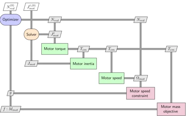
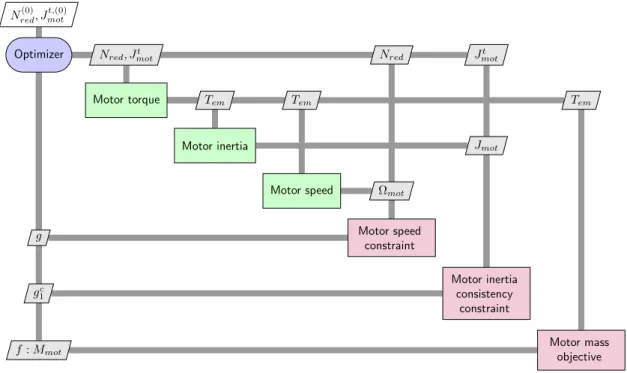
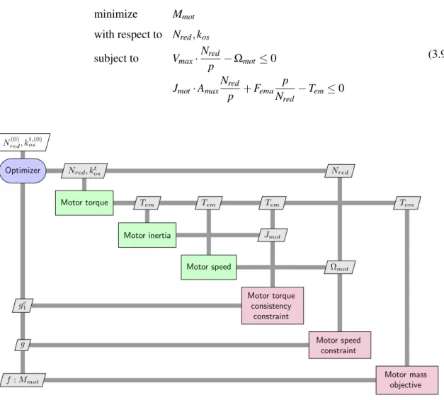
List of figures 21 3.5 XDSM diagram for IDF formulation of the EMA design problem . . . 64 3.6 XDSM diagram for Hybrid formulation of the EMA design problem . . . 65 3.7 XDSM diagram for NVH formulation of the EMA design problem . . . 66 3.8 Relative error vs iteration number for all formulations running the EMA design . . . 69 3.9 XDSM diagram for NVH formulation of the EMA design exploration problem . . . 70 3.10 Bipartite undirected graph of the EMA design problem . . . 73 3.11 Bipartite matched graph of the EMA design problem . . . 74 3.12 Bipartite graph of the EMA design problem after applying Step 3 of Algorithm 1 . . 74 3.13 Bipartite graph of the EMA design problem after applying Step 4 of Algorithm 1 . . 75 3.14 Bipartite directed graph of the EMA design problem with cycle (black) . . . 75 3.15 Bipartite directed graph of the EMA design problem with a cycle (black) and an
over-constrained (red) subgraph . . . 76 3.16 Bipartite directed graph of the EMA design problem with an under-constrained (blue)
subgraph . . . 77 3.17 Bipartite directed graph of the EMA design problem with NVH formulation . . . 78 3.18 A High-Level flow chart representing the global approach . . . 80 3.19 Original high dynamic EMA model implementation . . . 82 3.20 Original high dynamic EMA model implementation with bipartite graph . . . 82 3.21 Introduction of a over-constraint singularity in the high dynamic EMA model
imple-mentation . . . 83 3.22 Introduction of a under-constraint singularity in the high dynamic EMA model
imple-mentation . . . 83 3.23 Post-process high dynamic EMA model implementation . . . 84 4.1 Thrust vector control electro-mechanical actuator integration and architecture . . . . 88 4.2 Systemic design approach through requirements and design drivers . . . 89 4.3 System Breakdown Structure of electro-mechanical actuators with component design
drivers (oval), system design drivers (octagone) . . . 91 4.4 System Breakdown Structure of electro-mechanical actuators with component design
drivers (oval), system design drivers (octagone) and sizing scenarios (hexagone) . . . 92 4.5 System layer and component layer knowledge and associated models (adapted from
[195]) . . . 93 4.6 Actuator attachments positioning and parametrization . . . 94 4.7 Parvex Brushless motors parameters (Parker) . . . 95 4.8 Diameter vs Nominal Torque / Scaling law vs Linear regression . . . 97 4.9 Raw bearing data . . . 98 4.10 Pareto filtering of bearing data . . . 98 4.11 Actuator attachments positioning and parametrization . . . 100 4.12 Parametrization of the FEM analysis of the housing . . . 101
4.13 π0surrogate model validation . . . 103
4.14 Block Generation tab for component level modelling . . . 105 4.15 Sizing Procedure tab for system level modelling . . . 106 4.16 Decomposition of engineering design knowledge . . . 106 4.17 sub-system generation through hierarchical decomposition . . . 107 4.18 Component level coordination using graph-based methods . . . 109 4.19 Sizing procedure of thrust vector control actuator . . . 110 4.20 XDSM diagram of the thrust vector control electro-mechanical actuator optimization 112 4.21 environment of the framework . . . 114 4.22 XDSM diagram of the thrust vector control electro-mechanical actuator DOE . . . . 116 4.23 Exploration environment of the framework . . . 117 4.24 Interaction between optimization model and FMU model [54] . . . 118 4.25 Effect of motor inertia reduction on optimization results . . . 119 4.26 Effect of anchorage positioning . . . 120 4.27 Amount of work for the BOA framework implementation: number of code lines in
parenthesis . . . 123 5.1 Airbus A380 flight controls architecture [234] . . . 126 5.2 The F-35 full Power-by-Wire architecture (MOOG) . . . 127 5.3 Power requirements for an Airbus A320 aileron actuator [153] . . . 128 5.4 Underwing scoops for actuator cooling (EHA of the Airbus A350 aileron) [152] . . . 130 5.5 PFCAS design drivers (rectangle) and actuation design drivers (octagon) . . . 131 5.6 Reliability analysis for different number of mechanical devices in the load path . . . 132 5.7 Aileron control surface splitting on the Airbus A380 [2] . . . 132 5.8 Optimal Control Surface Layout for an Aeroservoelastic Wingbox [220] . . . 133 5.9 Example of on-hinge rotary EMA for future thin wing application: EMA + Power
Electronics (PE) in a same packaging [232] . . . 135 5.10 Rotary EMA architecture . . . 136 5.11 PFCAS sizing problem component design drivers (oval), actuation system design
drivers (octagon) and sizing scenarios (hexagon) . . . 141 5.12 Thermal response of preliminary design over the entire mission . . . 143 5.13 Brushless motor electromagnetic (left) and thermal (right) FEM simulations [207] . . 146 5.14 Harmonic Drive stiffness linear regression with respect to repeatable torque and
reduction ratio . . . 149 5.15 Flexible coupling topology . . . 149 5.16 Aileron rotary EMA integration and thermal configuration schematic . . . 150 5.17 Housing multi-physical FEM simulation . . . 152 5.18 Housing modal analysis . . . 152 5.19 Cut view of the actuator . . . 153
List of figures 23 5.20 XDSM diagram of the actuator sizing optimization problem . . . 155 5.21 Architecture of the system to be sized . . . 156 5.22 Actuator on-hinge integration with housing fixed to the wing . . . 156 5.23 Effect of control surface splitting on structure torsional moments . . . 157 5.24 Control surface FEM structural optimization result for one of five elementary surfaces 158 5.25 Effect of number of surfaces on total control surface structural mass . . . 158 5.26 Wing/Control surface attachment parameters . . . 159 5.27 XDSM diagram of the integrated actuator and aileron control surface optimization
problem . . . 162 5.28 Effect of number of surfaces on optimal overall system mass . . . 164 5.29 Effect of reducing the housing thermal resistance on optimal overall system mass . . 164 5.30 Single EMA mass breakdown for five surfaces configuration . . . 165 5.31 Aileron, elevator and the rudder control surface splitting configuration visualization
using OpenVSP [96] . . . 166 6.1 "Bucket" type thrust reverser [214] . . . 170 6.2 "Clam-shell" type thrust reverser [214] . . . 170 6.3 "Cold stream" type thrust reverser [214] . . . 171 6.4 Cold stream thrust reverser architecture (adapted from [190]) . . . 171 6.5 ETRAS and TRAS integration on a nacelle . . . 173 6.6 ETRAS power architecture . . . 173 6.7 ATO Deploy position dependent load profile shape . . . 176 6.8 Stow position dependent load profile shape . . . 177 6.9 ETRAS design drivers and sizing scenarios (non-exhaustive) . . . 179 6.10 ATO Deploy speed profile principle . . . 180 6.11 ATO deploy mission profile model at transcowl level in Dymola . . . 181 6.12 Power response to ATO deploy profile for 300 [mm/s] actuator maximum speed . . . 181 6.13 Morris sensitivity analysis for ATO deploy for parameters Vactmaxand Jre f . . . 182
6.14 Polynomial response surface for ATO deploy Pgen(left) and Pmot(right) . . . 182
6.15 Normal Stow speed profile principle . . . 183 6.16 Stow mission profile model at transcowl level in Dymola . . . 183 6.17 Power response to stow profile for 300 [mm/s] actuator maximum speed . . . 184 6.18 Morris sensitivity analysis for stow for parameters Vactmax and Jre f . . . 184
6.19 Degree 3 polynomial response surface for stow Pmot . . . 185
6.20 2-body / 2-heat sources motor thermal model . . . 185 6.21 Simplified motor thermal model . . . 185 6.22 Left slider jamming load case illustration . . . 187 6.23 Simplified interactions between design drivers and sizing scenarios of electrical
6.24 XDSM diagram of the ETRAS preliminary sizing model . . . 197 6.25 Comparison of ETRAS preliminary sizing mass breakdown for no jamming and
jamming . . . 198 6.26 Overspeed limit principle . . . 200 6.27 XDSM diagram of the ETRAS trajectory optimization problem . . . 203 6.28 Optimization results for different energy quantities objectives . . . 203 6.29 Optimization results for different objectives . . . 204 6.30 Effect of objective on the trajectory smoothness . . . 207 6.31 Simplified phasor diagram for synchronous electrical machine [47] . . . 208 6.32 Effect of saliency and angle α on electromagnetic torque . . . 209 6.33 Effect of angle α on electromagnetic torque and voltage for a saturated permanent
magnet synchronous motor (PMSM) . . . 210 6.34 XDSM diagram of the ETRAS trajectory and electrical power chain optimization
problem . . . 212 6.35 Optimization results for system level characteristics . . . 214 6.36 Optimization results for motor level characteristics . . . 215 A.1 XDSM diagram of the thrust vector control electro-mechanical actuator optimization 249 B.1 Actuator thermal behaviour investigation parametrization . . . 253 B.2 Actuator dynamic model architecture and interfaces . . . 254 B.3 Actuator dynamic thermal model architecture and interfaces . . . 254 B.4 Overall architecture of the actuator Dymola model . . . 255 B.5 Thermal FEM simulations of the motor (left) and the actuator housing (right) . . . . 255 B.6 Interaction between optimization model and FMU model [54] . . . 256 B.7 Thermal response of preliminary design over the entire mission . . . 256 B.8 Brushless motor electromagnetic (left) and thermal (right) FEM simulations [207] . . 257 C.1 ATO Deploy speed profile principle . . . 264 C.2 ATO Deploy speed and position for medium maximum speed . . . 264 C.3 ATO Deploy speed and position for maximum speed . . . 265 C.4 Normal Stow speed profile principle . . . 265 C.5 Normal Stow speed and position profile for medium maximum speed . . . 266 C.6 Normal Stow speed and position for maximum speed . . . 267 C.7 Overspeed limit principle . . . 268 C.8 Overspeed limit construction . . . 269 C.9 Overspeed limit parameters . . . 270
List of tables
1.1 Applications achieved during the thesis and their references. . . 14 2.1 Function evaluation counts for all architectures solving the Sellar Problem [90] . . . 52 3.1 Mathematical notation for MDO problem data (adapted from [136]). . . 62 3.2 Formulations characteristics for the EMA design problem. . . 66 3.3 Absolute error from known optimum for all formulations solving the EMA design
problem. . . 67 3.4 Number of function evaluations and derivative evaluations for all formulations solving
the EMA design problem. . . 68 3.5 Percentage of success in solving coupling variables consistency for all the
formula-tions exploring the EMA design space. . . 70 3.6 Mean, max., min. number of function evaluations and derivative evaluations for all
formulations exploring the EMA design space. . . 71 3.7 The success percentage in solving coupling variable consistency for all the
formula-tions at a new load requirement. . . 71 3.8 High Dynamic EMA model implementation parameters . . . 81 3.9 Post-process high dynamic EMA model implementation parameters . . . 84 4.1 Methodology summary . . . 122 5.1 Comparison between overall actuator mass, structural mass and total mass of a
conventional single aileron and split aileron configuration. . . 167 A.1 Inputs parameters values for the TVC EMA design . . . 249 A.2 Design variables, constraints and objective of the TVC EMA design . . . 250 A.3 System output values for the TVC EMA design . . . 251
Nomenclature
Acronyms / Abbreviations AAO All At Once
AC Alternating Current AD Automatic Differentiation AE Algebraic Equation
ARP Aerospace Recommend Practice ATC Analytical Target Cascading ATO Aborted Take Off
ATRU Autotransformer Rectifier Unit BFGS Broyden-Fletcher-Goldfarb-Shanno BLI Boundary Layer Ingestion
BLISS Bilevel Integrated System Synthesis
BOA BOA framework: Bind your models, Optimize your system, Accelerate your design CAD Computer Aided Design
CFD Computational Fluid Dynamics
CMA-ES Covariance Matrix Adaptation Evolution Strategy COBYLA Constrained Optimization By Linear Approximation CO Collaborative Optimization
CS Complex Step
DAE Differential Algebraic Equation DC Direct Current
DOE Design of Experiments DSM Design Structure Matrix
EBHA Electro Back-up Hydrostatic Actuator EEC Electronic Engine Controller
EHA Electro Hydrostatic Actuator EMA Electro Mechanical Actuator EMI Electromagnetic Interference
ETRAS Electrical Thrust Reverser Actuation System FCC Flight Control Computer
FD Finite Difference FEM Finite Element Method FMI Functional Mock-up Interface FMU Functional Mock-up Unit FTA Fault Tree Analysis
HSTA Horizontal Stabilizer Trim Electromechanical Actuator HVDC High Voltage Direct Current
IBC Individual Blade Control IDF Individual Discipline Feasible KKT Karush-Kuhn-Tucker
LHS Latin Hypercube Sampling LoC Lines of Code
MAUD Modular Analysis and Unified Derivatives MBSE Model-based Systems Engineering
Nomenclature 29 MDA Multidisciplinary Design Analysis
MDAO Multidisciplinary Design Analysis and Optimization MDF MultiDisciplinary Feasible
MDO Multidisciplinary Design Optimization
MOSFET Metal-Oxide-Semiconductor Field-Effect Transistor MSDO Multidisciplinary System Design Optimization
MTBF Mean Time Between Failure
NACA National Advisory Committee for Aeronautics ND Normal Deploy
NSGA2 Non Sorting Genetic Algorithm II NS Normal Stow
NVH Normalized Variable Hybrid ODE Ordinary Differential Equations PbW Power-by-Wire
PCU Power Control Unit
PDE Partial Differential Equation PDU Power Drive Unit
PFCAS Primary Flight Control Actuation System PLS Primary Locking System
PSO Particle Swarm Optimization RSM Response Surface Methodology SAND Simultaneous Analysis and Design SbW Signal-by-Wire
SD Symbolic Differentiation SHA Servo Hydraulic Actuator
SiC Silicon Carbide
SLSQP Sequential Least Square Quadratic Programming SNOPT Sparse Nonlinear OPTimizer
TB Thrust Bearing
THD Total Harmonic Distorsion TLS Tertiary Locking System
TRAS Thrust Reverser Actuation System TRCU Thrust Reverser Controller Unit TRL Technical Readiness Level TRS Thrust Reverser System TVC Thrust Vector Control
UDE Unified Derivatives Equations XDSM Extended Design Structure Matrix
Chapter 1
Context
1.1
The More Electrical Aircraft
Over the last century, aerospace engineering has evolved increasingly complex aircraft architectures. Today’s aircraft are complex systems that can be decomposed into different layers as shown in Figure 1.1.
Actuators Turbine Fuel Metering Unit Side-Stick Computer Electrical Harness Fuel Pump Environmental Control System Thrust Reverser
System
Flight Control
System Fuel System Anti-Icing System
Engine System Avionic System Landing Gear System
Ventilation System Thrust Reverser
Actuation System
Fuel Control
System Navigation System High Lift System
Fuel Supply System Ice Detection System Landing Gear Actuation System Propulsion Aircraft Airframe Aircraft Level System Level Sub-system Level Equipment Level Component Level
Electrical Motor Reducer RVDT Flexible Shaft Servovalve Inverter Compressor
Sub-component Level
Connector Screw Magnet Connecting Rod Pipe Seal Resistor
Fig. 1.1 Decomposition of a fixed wing aircraft (Non-exhaustive)
Environmental protection is a key driver for next generation aircraft as one of the goals of Flightpath 2050 are asked by ACARE European Council [121]. In order to drastically reduce fuel burn, emissions and noise, new aircraft concepts have been proposed. They investigated innovative propulsion systems [184], airframes, propulsion-airframe integration for boundary layer ingestion (BLI), and system and equipment architectures. New carbon alloys for structural components have helped reduce aircraft structural weight (the Airbus A350 and Boeing 787) while the use of winglets
has enabled a decrease in fuel consumption. The hybrid electric propulsion system and aft-mounted BLI concept of NASA’s Starc-ABL aircraft [91], illustrated in Figure 1.2, and Safran’s open-rotor engine architecture [39] illustrate such research trends .
Fig. 1.2 NASA’s Starc-ABL aircraft concept [242]
One research direction consists of electrifying propulsion and associated systems equipment by leveraging the advantages of electrical technologies in terms of integration, maintenance and power efficiency. Increasingly, this "more electrical aircraft" course of action is driving both the research and technological focus of the aeronautical industry and academica. The research on non-propulsive systems can be separated in two main themes as illustrated in Figure 1.3. The first theme investigates the replacement of pneumatic systems by electrical systems. The goals are the increase of the overall gas turbine efficiency, easier physical integration and simplified maintenance. The second theme investigates the concept of hydraulics-free aircraft which consists of replacing hydraulics with electrical systems. Particularly for large aircraft, the main goal is to reduce the overall weight while being easier to integrate and maintain. Furthermore, electrical systems are considered more environmentally friendly than hydraulic systems due to the removal of Skydrol fluid.
Fig. 1.3 The two axis of More Electrical Aircraft [87]
To date, non-propulsive electrical systems applications cover the complete range of Technical Readiness Levels (TRLs). For improving gas turbine efficiency, bleed valves have been replaced by an electrically driven compressor on the Boeing 787 aircraft [175]. This same aircraft also integrates electrical resistance elements that generate heat under the leading edge surface of the wing which promises lower power consumption than other de-icing technologies that bleed hot air from the engine.
1.1 The More Electrical Aircraft 3 Other major non-propulsive systems are actuation systems. Commercial aircraft need different actuation systems to fulfill their needs as illustrated in Figure 1.4.
Fig. 1.4 Actuation needs on a commercial aircraft [150]
They are used to deploy and retract the landing gear or to actuate flight control surfaces. Such systems also tend towards electrification. Electrical Thrust Reverser Actuation Systems (ETRAS) are composed of an electro-mechanical power chain and have been introduced on Airbus A380, Airbus A350 and COMAC C919 nacelles. The electrification of aircraft systems and equipment has also impacted flight controls. Fly-by-wire concepts introduced Signal-by-Wire (SbW) actuators using Servo Hydraulic Actuators (SHA) [152]. The hydraulic power used by SHA is generated by engine driven pumps and distributed by hydraulic networks. Power-by-Wire (PbW) actuators such as Electro Back-up Hydrostatic Actuators (EBHAs) and Electro Hydrostatic Actuators (EHAs), shown in Figure 1.5, were introduced in the back line of primary flight control surfaces on the Airbus A380 which enabled to reduce the aircraft overall weight by removing the tertiary hydraulic network [234].
Fig. 1.5 Description of an EHA [240]
The next step was to introduce PbW Electro Mechanical Actuators (EMAs) which enabled the removal of hydraulic fluid of actuators such as those described in Figure 1.6. This technology is currently in front line of two spoilers control surface of the Boeing 787 and Airbus A350-1000.
Fig. 1.6 Description of an EMA [240]
Furthermore, new electrical distribution systems are currently investigated to supply these non-propulsive electrical loads [87].
The integration of these new technologies can increase risks of unexpected behaviours of these critical systems leading to costly re-designs. In some investigated concepts, practical electrical technologies do not yet meet performances requirements and integration constraints. Despite being more efficient, these electrical technologies still generate losses. This heat excess has to be managed locally or else it could result in non-acceptable life time degradation or outright failures of boundary equipment and components. Additionally, these new electrical systems have to prove that they meet the stringent reliability and availability requirements of contemporary commercial aircraft. Therefore, one of the challenges for developing a more electrical aircraft is to master the design and integration of the next-generation mechatronic systems for actuation and other needs. For this purpose, several European and French research projects have investigated design methodologies and the development of physical prototypes.
1.2
Previous Research Projects and Previous Theses
Several research projects around the More Electrical Aircraft concept have driven research teams at both Institut Clément Ader in Toulouse and the Safran company.
The first were Electrically Powered Integrated Control Actuators – EPICA1 (1993-1997) and
Electrical Innovative Surface Actuation – ELISA1(1999-2001) which concerned alternative power
architectures for actuation systems. In the beginning of the 21st century, Power Optimized Aircraft – POA1 : 2002-2006 seeked ways to optimize the aircraft power architecture. Then projects like
More Open Electrical Technologies – MOET1(2006-2009) focused on developing methodologies
and technologies to enable better flexibility and use of electrical equipments. "Concept Innovant de Systémes d’Actionnement de Commandes de vols secondaires et de Servitudes" – CISACS1(2008
-2012)1,2and DRESS on the other hand concerned the electrification of landing gear actuation systems.
1Institut Clément Ader projects
1.3 Scope of the Thesis 5 COVADIS2(2008-2011) was a project between Airbus and Safran which resulted in flight tests of
electro-mechanical primary flight control actuators for ailerons [58]. SYRENA1,2 (2010 - 2013)
was a research project that involved industrial partners such as Safran and research laboratories. FRACASS2(2011-2014) investigated the concept of control surface splitting with rotary on-hinge
electro-mechanical actuators. It also investigated new architectures for regulation functions of gas turbines. Actuation 20151,2(2012-2016) involve a larger number of industrial and academic partners
and focused on the standardization of aerospace actuators and power electronics from landing gears to flight control. CORAC Genome2(2013-2018) funded by French research funds, had for objective
to develop future electrical equipment and systems. SYRENA II1,2(2014 - 2018), the successor of
this first project is currently under development.
In parallel of the previous research projects, many PhD thesis were involved. Some took place in the Actuation System team of Institut Clément Ader and greatly contributed to the work done in this thesis.
Liscouet-Hanke investigated aircraft power architectures and proposed a design methodology to better size them and enable aircraft level trade-offs [143]. Liscouet was the first PhD student in the laboratory to use scaling laws for the preliminary sizing of actuators [141]. Hospital focused on developing sizing models based on inverse simulation [109]. Giraud developed a methodology for the sizing of aircraft electrical networks [86]. Reysset developed preliminary design tools such as specification generation based on mission profile analysis [194]. Coic proposed a bond-graph based modelling approach to support the design of high dynamic hydraulic servo-actuators [43]. Sanchez proposed a methodology to generate algebraic analysis functions based on Finite Element Method simulations in order to utilize them during the preliminary sizing of actuation systems [207]. Monsimer investigated methods for enabling radical innovation during early preliminary design phases of fuel regulation systems [170]. Thauvin used design exploration of regional hybrid electrical aircraft concepts using multidisciplinary design and optimization methods [229].
On the other side of the atlantic, alternatives for more electrical systems and actuators have early been identified early [139]. Investigations of these alternatives were supported by US research programs such as Electrically Powered Actuator Design (EPAD) which leaded to the development of a primary flight control electro-mechanical actuator [130]. The final outcome was flight tests of the prototype on the F-22 [117]. Significant US military programs have provided the introduction of new technologies such as the F-22 [16] and the F-35 [197]. On the civil program side, the Boeing 787 more electric subsystems introduced the need for higher electrical power generation [19] as well as new electric drive technologies [34].
1.3
Scope of the Thesis
The eco-system and context where this thesis has emerged were previously outlined. They have greatly influenced the investigations in this thesis as well as other research work discovered over three
years. This part describes the scope of this thesis in terms of the studied systems, components and objectives.
1.3.1 Typical Systems
The systems studied in this thesis are in most cases actuation systems of Safran’s portfolio. Nev-ertheless, the methods and approaches developed in this thesis can be applied to other kinds of embedded mechatronic systems but will be here applied to aerospace actuation systems. An example of functional actuation chain is given in Figure 1.7.
Transf. Rectifier Motor DC Bus Filter Inverter Digital electronics Multiplication Transmission Reduction Limitation Ball screw On-board Network Motion
Functional electrical chain Functional mechanical chain
Functional actuation chain
Fig. 1.7 A typical actuation system functional chain
An actuation system functional chain can be decomposed into functional electrical and mechanical chains. The purpose of such systems are to move specific mobile structures such as control surfaces or, for example, a thrust reverser transcowl. The interfaces of such electrical systems are an electrical interface, generally an electric power supply, and mechanical interfaces which generally support where the system is integrated to the mobile structure. The electrical chain is used to transform the aircraft 3-phase electrical network into a local Direct Current (DC) electrical network. It is also in charge of distributing and controlling the required motion. The mechanical chain is there to adapt and distribute the power so that it is capable of the required motion. The electrical motor permits linking the electrical and the mechanical chain by transforming electrical power into rotational mechanical power.
Flight Controls Applications
The purpose of primary flight control systems is to control the aircraft trajectory by acting on movable surfaces. Ailerons are the primary flight control surfaces that act for roll control. They can be actuated by a linear electro-mechanical actuator like Figure 1.8 [58].
Other electro-mechanical topologies have been developed such as rotary electro-mechanical actuators like Figure 1.9.
Secondary flight controls are used to change the aerodynamic configuration of the aircraft during a particular flight phase. For example, the Horizontal Stabilizer Trim electro-mechanical Actuator (HSTA), illustrated in Figure 1.10, ensure the overall equilibrium of the aircraft during the given flight phases (e.g. climb, cruise or approach) [150].
1.3 Scope of the Thesis 7
Fig. 1.8 Linear Aileron Electro-Mechanical Actuator (Safran)
Fig. 1.9 Rotary electro-mechanical Actuator (Safran)
Thrust Reverser Application
Thrust Reversers are used to reverse the engine thrust just after touchdown during the landing phase in order to enhance wheel brakes sustainability, and land on shorter, wet or icy runways. Electrical thrust reverser actuation systems are one technology for actuation nacelle thrust reversers (Figure 1.11).
Fig. 1.11 Engine, nacelle and actuation system (CFM/Nexcelle/Safran)
The challenges linked to the design of these system examples are given and studied in this thesis.
1.3.2 Typical Components
These typical electro-mechanical systems are composed of mechatronic components required to fulfil the specified functions. The main design drivers (system level) of these components are outlined. Power Electronics
Power electronics are one main component of electrical actuation systems. The autotransformer is an electrical component that transforms an alternative electrical network into two alternative electrical networks with different voltage and current but the wave form and frequencies remain the same. The 3-phase autotransformer is widely used in aeronautics because of its compactness and is low Total Harmonic Distorsion (THD). They are often associated to rectifier that transform the two 3-phase electrical network into one DC network. In some case, interphase inductors are added to smoothen current pulses on the DC network. Inverters composed of semi-conductors are then used to transform the DC voltage into 1-phase or 3-phase voltage sources depending on the load they have to drive. Figure 1.12 shows pictures of common power electronic components.
The main design drivers of autotransformers and interphase inductors are the magnetic saturation of the core and the maximum temperature of the windings. For inverters, the main design drivers
1.3 Scope of the Thesis 9
(a) Example of autotransformer unit (Thales) (b) Example of Silicon Carbide (SiC) power core mod-ule (Microsemi)
Fig. 1.12 Two main electrical components of aerospace actuation systems
are the switching frequency and the maximum temperatures of diodes and transistors. Generally as the main design drivers include the thermal behaviour of components, the power electronic design includes the cooling system (heat sink, liquid...).
Another power electronics component used in regenerative energy devices is the braking resistor. Whereas as in some systems like electrical vehicles the regenerative energy is stored, some system use this device to transform the energy into heat that must be dissipate. One topology of this component is the planar resistance illustrated in Figure 1.13.
Fig. 1.13 Example of planar braking resistor
The main design drivers of this component are its resistance value and its maximum temperature capability.
Electrical Machines
The function of an electrical motor is to transform electrical power into mechanical power. Most types can operate reversibly as generators and transform mechanical power into electrical power. The most common technology used for embedded actuation systems is the permanent magnet brushless motor because of their reliability and high torque density obtainable [120]. For the power range (100 W -50 kW) of aerospace actuation systems, the armature is the stator and the inductor is the rotor with its permanent magnets. Applying an alternative voltage to the stator winding terminals produces an
electromagnetic field that interacts with the rotor magnet field which produces an electromagnetic torque that leads to the rotation of the non-fixed part (generally the rotor). Two motor typologies exist for the power range of aerospace actuation systems:
• High torque motor – They generally are capable of generating high torque at low speed. Their ratio factor (Length/Diameter) is low (0.25-1) and the number of pole pairs is large (> 10). They are well suited for direct-drive architectures.
• High speed motor – They are used for high speed applications with high reduction ratios to the load. Their ratio factor (length/diameter) is high (1-3) and the number of pole pairs is small to medium (2 - 10).
(a) Example of high torque motor (Kollmorgen) (b) Example of high speed motor (Parker)
Fig. 1.14 Two main motor typologies for aerospace actuators
The main design drivers of brushless motors are maximum torque, torque ripple, maximum winding temperature, inertia, maximum speed and flux weakening strategy.
Mechanical Transmission
Mechanical gears or reducers sets adapt the mechanical power from one shaft to another. Multiple technologies of gears are available in aerospace applications with some examples shown in Figure 1.15.
Spur gears are the most common gears with both shafts in parallel. Bevel gears on the other side the two shafts are not parallel but form an angle which is in most cases is equal to 90◦as shown in
Figure 1.15a. More complex gear such as planetary gears are used for high torque application as it is transmitted through different planet gears but also to have the same input and output shaft axis. Their main design drivers are tooth bending stress and contact stress which respectively lead to tooth breakage and pitting. Contact stress has an effect on the pinion size whereas tooth bending stress has an effect on the tooth shape and size. Other selection parameters such as maximum/fatigue torque and reduction ratio are also design drivers. Harmonic Drives, represented in Figure 1.15c, have advantages such as lack of backlash, compactness and high reduction ratio (30 – 150) compared to classical gears (2.5 – 8).
1.3 Scope of the Thesis 11
(a) Example of straight bevel gear (b) Example of planetary gear (c) Example of Harmonic Drivegear
Fig. 1.15 Three examples of gear technologies used for aerospace actuators
Compound gears were first developed for aircraft flap systems and can take really high torques due to the fact that the torque is shared between two large teeth. Despite their better torque capacity compared to planetary gears, they have lower direct efficiency. Magnetic gears are also investigated because of their torque limitation function but are not yet flying [111].
Fig. 1.16 Compound planetary gear [230]
In order to transform a rotational power into a translational power, nut screw devices can be used (Figure 1.17). These devices have four degrees of freedom [123]. Two parts of the device have to be fixed in order to provide the function, either the nut translation or rotation combined with the screw rotation or translation. Roller screws are one main technology of nut screw and have the particularity to handle high torques but with small pitches. On the contrary, ball screws handle smaller torques but can be designed for higher pitches and at lower cost.
(a) Example of roller screw (SKF) (b) Example of ball screw (Umbra)
The main design drivers of nut screws are the maximum/fatigue axial load and buckling load. Pitch is also a design driver and often leads to the technological choice between roller screw and ball screw.
Flexible shafts transmit rotary motion through their high rotational stiffness whilst allowing misalignment between input and outputs shafts, as shown in Figure 1.18.
Fig. 1.18 Flexshaft are similar to gimbals (S. S. White)
Their main designs drivers are maximum speed, stiffness, fatigue and peak torque.
1.3.3 Objectives
The design of actuation systems at Safran is a collaborative process between different teams of the design office: embedded software, digital electronics, power electronics, electrical machine, control, mechanics, system architecture and modelling.
This thesis mainly focuses on the sizing aspects of actuation systems which has implications for the power electronics, electrical machine, control, mechanics, system architecture and modelling teams.
Different design process approaches can be used for teams to interact during the development of actuation systems. The sequential design process illustrated in Figure 1.19 relies on strong hypothesis on subsystems interactions generally based on project post-mortem and designer experience. Such process does not guarantee system performances optimality and has no degree of freedom along the design process. System specifications Mechanical transmission Electrical machine Power electronics
Fig. 1.19 Sequential design process of actuation system
The sequential iterative design process, given in Figure 1.20, enables interactions between subsystem design teams. This process is more efficient that the sequential process but often results in costly human iterations. Additionally, it does not offer enough degree of freedom to obtain system
1.3 Scope of the Thesis 13 performances optimality as design decisions are still made without seeing the global effect on the system. System specifications Mechanical transmission Electrical machine Power electronics
Fig. 1.20 Sequential iterative design process of actuation system
The sequential iterative process is similar to the approaches used in Safran’s design office. This process is not optimal for system performance and development costs. There is an industrial need to change this process in order to be more competitive and sustain the design office know-how. Hence, the industrial objectives of this thesis have be explicitly defined:
IO1. Develop a holistic sizing methodology and an associated software tool.
IO2. The methodology shall enable knowledge capitalization and collaboration.
IO3. The software tool shall handle analysis and optimization of coupled systems.
IO4. The software tool shall provide reasonable analysis and optimization times.
IO5. The methodology and software tool shall be tested on a realistic industrial product.
Therefore, these can be summarize in one main objective which is to propose a practical and more integrated design approach for electro-mechanical actuation systems supported by a software tool which can be deployed in an industrial design office. However, these objectives raise some important research questions:
RQ1. How should this sizing methodology be incorporated in the overall design process?
RQ2. Who will be the users of such software tool?
RQ3. How to capitalize knowledge and collaborate in a multidisciplinary design office?
RQ4. How to interface different engineering specialization design tools?
RQ5. Can Multidisciplinary Design Optimization techniques be made available to unexperienced users?
RQ6. What is a reasonable computation time in a design office? What are the potential solutions to reach it?
1.3.4 Applications
The work achieved during this thesis has contributed to different applications and publications that are not all mentioned in this manuscript. Table 1.1 gives a synthesis of these contributions.
Table 1.1 Applications achieved during the thesis and their references.
System Key topics References
Fuel Metering Pump Thermal/Hydraulic [170]
DC/DC Buck Converter Thermal/Electric [208, 207] Aileron linear EMA Thermal/Co-simulation [54] Thrust Vector Control EMA High dynamic/Vibrations Chapter 4
Aileron Rotary EMA with lever arm Control [51]
Aileron Rotary EMA Thermal [210]
Primary Flight Control Actuation System Structure Chapter 5 and [53] ETRAS Power chain/Mission profile Chapter 6 and [52]
1.4
Dissertation Overview
Chapter 1 introduced the context of this thesis in terms of working environment, previous work, typical systems and components. It also outlined the needs which led to the creation of this collaboration between Safran and Institut Clément Ader and the objectives that were defined.
Chapter 2 is a state of the art of engineering design approaches which is then used to determine the methods that can be used during sizing activities. First, intrinsic challenges of mechatronic systems are outlined. The methods and tools used in Model-based Design are studied. Systemic approaches used in engineering design are then presented. Finally, different design optimization methods are investigated.
Chapter 3 proposes a new multidisciplinary system design optimization formulation adapted to sizing optimization problems, and compares it to existing formulations. Graphs and algorithms which help designers in the formulation of design optimization problems are described.
The core of this thesis is the development of a sizing methodology and its associated framework. A detailed description is provided in Chapter 4.
Chapter 5 is a flight control case study. The design of a primary flight control actuation system is achieved. The actuation system is composed of rotary electro-mechanical actuators and control surface structure. The concept of control splitting is investigated.
Chapter 6 is a design case study that concerns an electrical thrust reverser actuation system. First, a conceptual design is achieved. Finally, a more detailed design is performed for mission profile and motor control strategy optimization.
Results and lessons learned are summarized in Chapter 7. Conclusions are made and perspectives are outlined.
Chapter 2
The State of the Art for Engineering
Design Approaches
2.1
Introduction
The field of aerospace covers a large variety of products, disciplines and domains. Consequently, aircraft engineering activities cover many design problems. It is proposed to outline four categories of problems, their associated problem indicators and an associated example. The nature of the interfaces between disciplines is considered. The considered nature of disciplinary models throughout the thesis are:
• 3D models correspond to detailed geometry analysis using Finite Element Method (FEM), Computer Aide Design (CAD)
• 1D models represent transient time domain simulations • 0D models correspond to algebraic modelling
The objective of aircraft conceptual design is to define a specification of aircraft sub-systems and equipment. This requires the participation of four fundamental disciplines: aerodynamics, flight dynamics, propulsion and structures. Furthermore, it must consider a sizable number of specialist dis-ciplines like sizing scenarios (maneuvers, mission profiles, ...) or analysis (aerodynamics, propulsion, ...). It involves high number of empirical models representing the inputs from different disciplines, with a relatively low fidelity based on, previous designed and manufactured aircraft. The nature of the couplings are typically 0D/0D between fundamental discipline analyses and 0D/1D for mission profiles.
Sub-system design has an objective to deliver equipment and component level specifications. For example, the aircraft electrical network design involves a very large number of sizing scenarios (thousands [87]) due to many failure cases (short circuit, fire, ...) and many components (static converters, commuters ...). The nature of couplings is mostly 0D/0D.
The purpose of equipment design is to generate an accurate specification of components. For example, electro-mechanical flight control actuator design requires a relatively high number of disciplines. Sizing scenarios come from operational and failure modes (continuous torque, wind gust, ...) and design drivers at the components level (mechanical stress, maximum temperature capability, ...). They can be represented using differential algebraic equations (0D-1D) or algebraic equations (0D). They require also estimation of component characteristics (inertia, thermal resistance, ...) which can be evaluated using estimation models like scaling laws or surrogate models of FEM simulations (0D) or directly detailed simulations (3D). The nature of couplings range from 0D/0D, 0D/1D, 1D/1D to 0D/3D.
The objective of component design is to justify detail component needs. For example, high fidelity wing design involves some twenty design drivers (wing span, twist, rib thickness, ...) which are represented by the two fundamental disciplines of aerodynamics and structural mechanics. They are evaluated using complex structural mechanics FEM models and aerodynamic Computational Fluid Dynamics (CFD) models [126]. Here the coupling is achieved through commonly held boundary conditions of the FEM and CFD simulations and therefore represents a 3D/3D coupling. Figure 2.1 classifies a non-exhaustive list of problems in terms of number of disciplines, model fidelity and nature of couplings. El ectr ic al ne tw ork de sign (0 D)
High fidelity wing design (3D) Number of disciplines Model fidelity
Fig. 2.1 Classification of Aircraft Engineering Design Problems (Non-Exhaustive)
This introduction has outlined that aircraft design introduces a large variety of potential couplings at many levels. Hence, there is a need for design methodologies to deal such multidisciplinary problems.
2.2
Challenges of Embedded Mechatronic System Design
Mechatronics are the synergic and systemic regroupment of mechanical engineering, electronics, control, computer science and systems engineering as illustrated in Figure 2.2. A mechatronic system

![Fig. 2.10 Secondary power flows for an Airbus A230 type single-aisle aircraft [143, 150]](https://thumb-eu.123doks.com/thumbv2/123doknet/11459182.291039/56.892.226.680.358.606/fig-secondary-power-flows-airbus-single-aisle-aircraft.webp)
![Fig. 2.34 Equations for computing total derivatives in a general system of equations [157]](https://thumb-eu.123doks.com/thumbv2/123doknet/11459182.291039/80.892.141.775.544.983/fig-equations-computing-total-derivatives-general-equations.webp)
![Fig. 2.35 Derivation of the analytic methods for direct and adjoint froms [157]](https://thumb-eu.123doks.com/thumbv2/123doknet/11459182.291039/81.892.114.761.418.893/fig-derivation-analytic-methods-direct-adjoint-froms.webp)
![Fig. 2.38 Existing design tools classification and objective sizing tool location (adapted from [101])](https://thumb-eu.123doks.com/thumbv2/123doknet/11459182.291039/85.892.218.657.632.1012/existing-design-tools-classification-objective-sizing-location-adapted.webp)