HAL Id: tel-01958553
https://tel.archives-ouvertes.fr/tel-01958553
Submitted on 18 Dec 2018HAL is a multi-disciplinary open access archive for the deposit and dissemination of sci-entific research documents, whether they are pub-lished or not. The documents may come from teaching and research institutions in France or abroad, or from public or private research centers.
L’archive ouverte pluridisciplinaire HAL, est destinée au dépôt et à la diffusion de documents scientifiques de niveau recherche, publiés ou non, émanant des établissements d’enseignement et de recherche français ou étrangers, des laboratoires publics ou privés.
Xuan Huynh Pham
To cite this version:
Xuan Huynh Pham. Oxidative pyrolysis of biomass pellets in a fixed bed. Other. Université de Perpignan, 2018. English. �NNT : 2018PERP0029�. �tel-01958553�
Délivré par
UNIVERSITE DE PERPIGNAN VIA DOMITIA
Préparée au sein de l’école doctorale Energie et
Environnement- ED 305
et de l’unité de recherche BioWooEB-CIRAD
Spécialité :
Sciences de l'Ingénieur
Présentée par
Xuan-Huynh PHAMSoutenue le 22 Octobre 2018 devant le jury composé de
M. Gilles FLAMANT, Professeur, PROMES, Perpignan Président
M. Hervé JEANMART, Professeur, UCL, Louvain-la-Neuve, Belgique Rapporteur
M. Yann ROGAUME, Professeur, ENSTIB/LERMAB, Epinal Rapporteur
Mme. Capucine DUPONT, Docteur, HDR, UNESCO-IHE, Delft, Pays-Bas Examinateur
M. Sylvain SALVADOR, Professeur, IMT Mines, Albi Examinateur
M. Bruno PIRIOU, Docteur, CIRAD, Montpellier Encadrant
TITRE DE LA THESE
À mes chers parents To my beloved parents Dành tặng bố mẹ kính yêu
As quoted in a Vietnamese proverb:
“Không thầy đố mày làm nên”
I dare you to achieve success without a teacher
To complete this dissertation, first, I would like to express my great thanks to my “teachers” (my supervisors) Dr. Laurent Van de Steene and Dr. Bruno Piriou. A “MERCI BEAUCOUP” to Laurent not only for assisting in my dream of pursuing a PhD in France and for taking the time to support me in all aspects of my work, but furthermore also for supporting me to join to a great research network in both countries France and Vietnam. His rigorous supervision provided me a logical and effective methodology of doing research that I constantly apply in my current work. For example, planning for tests; publications and writing; and taking minutes for meetings. In this dissertation, he always provided me new insightful suggestions on structure, content, even some scientific terms and patiently explained me until I get the picture of everything. To Bruno, I would say thanks for all the patience he had with me at all times and for taking care of me as a brother along with my family. For all the troubles concerning equipment, experiments, measurements and administrations, whenever I was in need, he worked his magic and then everything went smoothly. He always arrived “tombe a pic” as the French people say. He taught and encouraged me that “everything is possible” and now I believe this is true. I feel very lucky to have worked with two wonderful supervisors!
A third supervisor that I would like to express my gratefulness and my respect to is Pr. Sylvain Salvador. Many thanks Sylvain for your time and your attention for me during the last three years. Your directions, comments and remarks always provided me new insight to raise my reports and communication documents up to a higher level.
A special thanks to all the members of the steering committee Dr. Gilles Vaitilingom, Dr. Jean Michel Commandré, Dr. Capuccine Dupont, and Dr. Christelle Perilhion for “piloting” the ship named “Huynh’s thesis” and helping the ship to dock at the SUCCESS port.
Other special thanks to the excellent technicians Jérémy Valette, Laurent Martin, Eric Martin, and Charline Lanvin, without their help this work could have never been performed and finished.
In addition, during my thesis I received great helps for the administrative works from Nathalie Troalen, Isabelle Châlon, and later Coline Brau. Thank you all.
cultural environment where you always treated me as a part of this family. Thank you Dr. Sylvie Mouras, Dr. François Pinta, Dr. François Broust, Dr. Joël Blin, and Dr. Anthony Benoist for your advices and encouragement for my work. Thank you to all the PhD students, intern students and post-doctorats at the BioWooEB, especially the three sounding boards Luke Stover, Gwendal Vonk, and Dr. Sébastien Wahl. And merci beaucoup Jérôme Singla pour les expériences “after work” exceptionnelles.
Besides the people in my institution, I would like to thank the rest of my dissertation jury for having accepted to attend my dissertation defense as well as their insightful comments, which motivated me to complete my research from various perspectives. Merci à vous Pr. Gilles Flamant, Pr. Yann Rogaume, et Pr. Hervé Jeanmart.
In addition, I would like to say thank to all my colleagues in the CleanED laboratory, University of Science and Technology of Hanoi, who helped me a lot to achieve the scholarship as well as encouraging me during my thesis.
Finally, I would like to thank my family, friends, my darling Hang and my daughter Bơ (Karine Tu Anh) for all their support, their love and their trust in me.
This work has been financially supported by CIRAD, French and Vietnamese governments.
Merci à toutes et à tous !
Chân thành cảm ơn mọi người !
Montpellier 2018 PHẠM Xuân Huỳnh
La gazéification étagée est une technologie innovante pour la production d’énergie renouvelable de petite et moyenne puissances, pour laquelle l'élargissement de la gamme de biomasses utilisables constitue un enjeu majeur de développement. Cette thèse porte spécifiquement sur la pyrolyse oxydante en lit fixe, première étape clé du procédé, qui conditionne fortement la performance et la fiabilité de cette technologie. Trois types de biomasses – pin, miscanthus, et paille – conditionnées sous forme de granulés ont été étudiés. Une étude expérimentale a été réalisée sur un réacteur pilote à lit fixe de 20 cm de diamètre et 1.6 m de hauteur permettant de reproduire des conditions opératoires proches de celles rencontrées durant l'étape de pyrolyse dans les gazéifieurs industriels. Le fonctionnement du procédé pour les trois biomasses a été caractérisé par la mesure du ratio air/biomasse, des températures, des rendements en charbon, gaz permanents et condensables et de leurs compositions.
Une attention particulière a été portée à la zone d'oxydation qui se propage verticalement vers le haut dans le lit de biomasse. Une méthodologie a été développée pour mesurer la vitesse de propagation, l'épaisseur et le tassement de cette zone et étudier l'impact de la nature de la biomasse. Dans un lit de granulés de bois, la vitesse et l'épaisseur de la zone d'oxydation est 25 % plus faible que dans un lit de granulés de paille ou miscanthus. L'effet catalytique des matières minérales sur les réactions de pyrolyse primaire et secondaire et son impact sur le fonctionnement du procédé, ont également été mis en évidence.
ii
Staged gasification is an innovative technology for small and medium renewable energy production. The expansion of the range of usable biomass remains a major obstacle to development. This thesis focuses specifically on the oxidative pyrolysis in a fixed bed, the first step of the process that strongly influences the performance and reliability of this technology. Three types of biomass- pine, miscanthus and wheat straw - in form of pellets were studied. An experimental study was carried out in a pilot fixed bed reactor of 20 cm diameter and 1.6 m height allowing the reproduction of similar conditions to those existing in the pyrolysis step of an industrial gasifier. The process operation for the three biomasses was characterized by measuring the air/biomass ratio, bed temperature, yields and compositions of char, permanent gases and condensates.
A particular attention was paid on the oxidation zone which propagates upward towards the raw biomass. A method was developed to measure the propagation velocity, thickness and the compaction of the oxidation zone and to study the impact of the biomass nature. Velocity and thickness of this zone were 25 % lower in a fixed bed of wood pellets than in beds of wheat straw or miscanthus. Catalytic effect of the mineral matters on primary and secondary pyrolysis reactions and their impact on the process operation have been highlighted.
RÉSUMÉ ... i
ABSTRACT ... ii
TABLE OF CONTENTS ... iii
GENERAL INTRODUCTION ... 1
CHAPTER I BIOMASS-TO-ENERGY ... 5
I.1. General context ... 5
I.1.1. Biomass ... 5
I.1.2. Biomass potential and worldwide usage ... 7
I.1.3. Biomass conversion processes ... 10
I.1.3.1. Physicochemical and biochemical conversion ... 11
I.1.3.2. Thermochemical conversion ... 12
I.2. Lignocellulosic biomass and thermochemical processes ... 13
I.2.1. Lignocellulosic biomass: structure, composition and properties ... 13
I.2.1.1. Structure of lignocellulosic biomass ... 13
a. Polymer constituents ... 14
b. Minoritary constituents ... 16
I.2.1.2. Composition of lignocellulosic biomass feedstock ... 17
a. Elemental analysis ... 18
b. Proximate analysis ... 19
c. Summary of expressing biomass composition ... 21
d. Energy content ... 21
I.2.1.3. Properties of lignocellulosic biomass ... 22
a. Physical properties ... 22
b. Thermochemical properties ... 23
I.2.2. Thermochemical conversion processes ... 26
I.2.2.2. Gasification technologies ... 30
a. Fixed bed gasifiers ... 31
b. Fluidized bed gasifiers ... 34
c. Entrained flow gasifier ... 34
I.2.2.3. Pyrolysis technologies ... 36
a. Carbonization for charcoal production ... 37
b. Fast pyrolysis for bio-oil production ... 38
I.3. Conclusion ... 39
CHAPTER II OXIDATIVE PYROLYSIS OF BIOMASS IN A FIXED BED ... 41
II.1. Biomass pyrolysis ... 41
II.2. Fundamentals of biomass pyrolysis ... 43
II.2.1. Primary pyrolysis reactions ... 43
II.2.2. Secondary pyrolysis reactions ... 47
II.2.2.1. Homogeneous reactions ... 48
II.2.2.2. Heterogeneous reactions ... 51
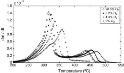
II.2.2.3. Influence of oxygen on the pyrolysis reactions ... 52
II.3. Oxidative pyrolysis in a fixed bed ... 54
II.3.1. Propagation of the oxidation zone in a fixed bed. ... 55
II.3.2. Structure of the oxidation zone ... 57
II.3.3. Oxidative pyrolysis products ... 60
II.4. Positioning and objectives of the thesis ... 61
II.4.1. Positioning of the PhD thesis ... 61
II.4.2. Biomass pellets for valorization of new biomass sources ... 62
II.4.3. Industrial challenges and PhD scientific objectives ... 63
II.4.4. Methodology ... 64
CHAPTER III MATERIALS AND EXPERIMENTAL METHODOLOGY ... 67
III.2. Fixed bed reactor ... 69
III.2.1. Two operating mode: batch and continuous ... 70
III.2.2. Reactor chamber ... 71
II.2.3. Biomass feeding ... 73
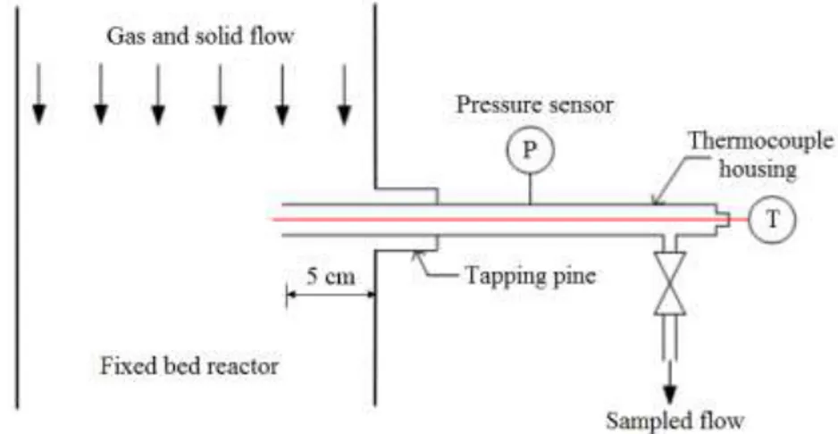
III.3. Analysis and instrumentation ... 74
III.3.1. Sampling system ... 74
III.3.2. Permanent gases ... 76
III.3.3. Char ... 78
III.3.4. Condensates ... 79
III.3.5. Temperature measurement ... 80
III.3.6. Bed height measurement ... 82
CHAPTER IV OXIDATIVE PYROLYSIS OF BIOMASS IN CONTINUOUS OPERATING CONDITIONS ... 85
IV.1. Experimental procedure ... 86
IV.1.1. Transient period ... 86
IV.1.2. Stationary period ... 87
IV.2. Bed temperature ... 88
IV.3. Air/biomass ratio and equivalent ratio ... 89
IV.4. Compositions of the oxidative pyrolysis products ... 90
IV.4.1. Composition of the char ... 90
IV.4.2. Composition of the permanent gases ... 91
IV.4.3. Composition of the condensates ... 92
IV.5. Mass and energy balance ... 93
IV.5.1. Mass balance ... 93
IV.5.2. Repartition of energy in the products ... 96
IV.6. Detailed enthalpy balance establishment ... 98
IV.6.1. Methodology ... 99
IV.6.1.3. Determination of the heat losses ... 102
IV.6.2. Results ... 104
IV.6.3. Sensitivity analysis of the enthalpy balance ... 107
IV.6.3.1. HHV of biomass ... 107
IV.6.3.2. HHV of condensates ... 108
IV.6.3.3. Composition of biomass... 108
IV.6.3.4. Composition of condensates ... 108
IV.6.3.5. Water fraction in the condensates ... 109
IV.6.3.6. Heat capacity of the condensates ... 109
IV.7. Conclusions ... 110
CHAPTER V OXIDATIVE PYROLYSIS OF BIOMASS BATCH OPERATING CONDITIONS .... 113
V.1. Experimental procedure ... 114
V.2. Methods for the characterization of the oxidation zone ... 114
V.2.1. Bed compaction ... 114
V.2.2. Propagation velocity ... 115
V.2.3. OZ Thickness ... 119
V.2.4. Temperature profile ... 119
V.2.5. Data processing ... 121
V.3. Results and discussion ... 122
V.3.1. Air/biomass ratio and equivalent ratio ... 122
V.3.2. Bed compaction rate ... 122
V.3.3. Propagation velocity of the oxidation zone ... 124
V.3.4. Thickness of the oxidation zone ... 126
V.3.5. Temperature field ... 127
V.3.6. Product yields and mass balance ... 128
V.3.7. Oxidative pyrolysis products ... 130
V.3.7.1. Char ... 130
V.3.7.3. Organic condensates ... 133
V.3.8. Repartition of energy in the products ... 133
V.4. Conclusions... 135
GENERAL CONCLUSION ... 137
REFFERENCES... 139
APPENDICES ... 149
A. Wood chips- raw biomass material and difficulties ... 149
B. Standard enthalpy of formation of water and permanent gases ... 152
C. Heat capacity as function of temperature ... 153
D. Detailed enthalpy balance for the case of pine oxidative pyrolysis ... 154
E. Detailed enthalpy balance for the case of miscanthus oxidative pyrolysis ... 155
F. Detailed enthalpy balance for the case of wheat straw oxidative pyrolysis ... 156
G. Numerical tools for the experimental data treatment ... 157
LIST OF FIGURES ... 161
-GENERAL INTRODUCTION
Reliance on fossil fuels and their derived products by mankind raises many tremendous concerns on economy and environment such as energy shortages and global warming. Consequently, seeking an alternative source for the fossil fuels is necessary to overcome these problems. Along with other renewable energy sources such as wind, solar, hydropower, etc, biomass has been receiving an increased attention. Known as an abundant and reliable source, biomass plays an important role in the renewable energy domain nowadays. Depending on the type and properties of biomass, there are various types of technology for the biomass conversion into energy and material including biochemical, thermochemical and physicochemical conversion. Among them, the thermochemical processes are the most suitable technology for the conversion of the most common type of biomass, i.e. lignocellulosic biomass, into various convenient energy forms such as heat, electricity and gaseous, liquid or solid fuel. In recent years, gasification has emerged as an innovative technology to produce the synthesis gas or syngas from biomass, which is then used as fuel in an engine, electricity generator or a preliminary material to synthesize other chemical compounds.
In this manuscript, we focused on an advanced technology called air staged gasification. It shows the advantage over other gasification technologies of producing a higher efficiency and a clean syngas. The key solution of this technology lies on its specific design with two separated reactors: one pyrolyzer and one gasifier. Thus, the main stages of the biomass gasification process are separated physically that enable better control the whole gasification process. Moreover, pyrolysis stage in the pyrolyzer is particularly important as it produces the char, permanent and condensable gases that are subsequently cracked, reformed, oxidized, and gasified in the next stages in the gasifier. Understanding and controlling the pyrolysis stage was the main focus of this study.
Indeed, in the staged gasifiers, pyrolysis occurs in a continuous fixed bed. The energy needed for the heating, drying, and endothermic reactions of the conversion is provided by partial oxidation of the biomass. The pyrolysis process is said autothermal and referred here as “oxidative pyrolysis”. During oxidative pyrolysis in continuous downdraft reactors, the biomass and air are fed at the top of the reactor and char and pyrolysis gases are removed from the bottom. An Oxidation Zone (OZ) separates the unreacted biomass from the char and is the
location of several complex and coupled transformations or reactions. The stabilization of the OZ inside the bed is of particular interest for operators for two reasons:
- The top of the bed is maintained at a low temperature, thereby facilitating the control of the process and limiting the production and deposition of tar;
- A higher temperature zone is created below the OZ that favors tar cracking when crossing it.
The control of this OZ is complex as it depends on many parameters such as air and biomass flux as well as density and composition of the biomass. However, this control has been mastered by operators and constructors for a few years but only for wood chips with relatively low moisture content.
Extension of the biomass nature in such processes is clearly a big challenge for biomass gasification. Indeed, biomass with highest potential, from agricultural residues or herbaceous crop, causes technical problems due to their low density and high ash content when compared to wood chips ones. Such low-density and fibrous materials are not favorable to regular vertical flows in the reactor and are known to be responsible for bridging or channeling in the reactors and particularly when thermochemical transformations occurs. High ash content biomass affects the reactor behavior because of the inert mass of the ashes as well as its catalytic role on the transformations.
Densification is clearly the solution to meet the low-density technical issue just described regarding oxidative pyrolysis in continuous fixed beds. However, high density of biomass pellets will behave of course differently than wood chips due to significant difference in volumic energy density, heat and mass transfer mechanisms, and in a lesser extent vertical flow in the reactor. These issues have been investigated in the previous PhD [1], by comparing the behaviors of wood pellets and wood chips during oxidative pyrolysis. Furthermore, pelletization can above all open fixed bed gasification technologies to new high potential biomasses such as agricultural residues and energy crops.
In this work, we focused on the behaviors during oxidative pyrolysis of wheat straw and miscanthus pellets as the best representative of agricultural residues and herbaceous energy crops. The behavior of pine pellets as classical biomass for such process was used as reference. Thus, the objective of this PhD was to provide practical answers to process designers and operators regarding the oxidative pyrolysis stage of a global process. In particular, we have done our best to measure some important physical quantities such as:
- Equivalence ratio (ER);
- Yields and compositions of the pyrolysis products; - Temperature field.
The impact of the biomass nature on these quantities was another major industrial concern that we investigated.
For this purpose, in the first step, we used a pilot fixed bed reactor enabling operation in continuous mode as representative of an industrial two-stage gasifier. Process performance in terms of temperature, air/biomass ratio, equivalence ratio were quantified. Yields and compositions of pyrolysis products including char, condensates and permanent gases were determined. Mass and energy balances were established. A sensitivity study on the accuracies and impacts of some experimental and thermodynamic data on the energy balance was performed.
In the second step, we operated the reactor in batch operation mode to finely characterize some specific features of the OZ that we could not perform in continuous mode: propagation velocity, thickness, and compaction. A new methodology accompanied with data treatment tools were set up. Influence of biomass nature on such process, especially ash content and composition, was discussed through the oxidative pyrolysis of three biomasses.
This manuscript is divided into five chapters. Chapter I provides general context related to biomass-to-energy via thermochemical conversion. Chapter II highlights the most significant contributions from the literature on biomass oxidative pyrolysis. It ends with the positioning and objectives of the PhD thesis. Chapter III deals with the materials and methods. It covers three aspects: characterization of the biomass pellets; descriptions of the experimental apparatus; sampling and analyzing pyrolysis products. Chapter IV and V present the detailed experimental studies in continuous and in batch modes.
-CHAPTER I
BIOMASS-TO-ENERGY
The world energy demand is currently satisfied mainly by fossil fuels including coal, crude oil and natural gas. However, these resources are limited and non-renewable. In addition, reliance on fossil fuels and their derived products forces human being to face with many tremendous concerns on economic development and environment such as energy shortage and global warming. Consequently, seeking for renewable energy sources is necessary, and biomass has been receiving increased interest as an alternative to fossil fuels.
Biomass is a renewable energy source as it is derived of living organic compounds including dedicated materials and wastes. Compared to other common forms of renewable energy sources, i.e. wind, solar, biomass is the world largest and most sustainable energy resource [3]. In addition, considering the cost effectiveness and availability factor, biomass-based technologies are becoming popular as they have edge over other renewable energy technologies. Moreover, they have a high flexibility to adapt existing fossil-fuel-based systems. They allow converting biomass into various convenient energy forms such as heat, electricity, as well as solid, liquid and gaseous fuels. Depending on the needs and the biomass properties, various technologies for the conversion were proposed.
In recent years, the development of biomass to energy processes has played an important role in easing the transition of using biomass as alternatives to the fossil fuels. For this purpose, two challenges remain essential: (i) understanding biomass conversion processes to better control the operation and optimize the performance; and (ii) expanding sources of usable biomasses. This section aims at presenting first some basic features related to biomass and its properties, focusing on the lignocellulosic biomass. Then, the chapter describes principles of different biomass conversion processes. Finally, the main thermochemical technologies available for lignocellulosic biomass conversion are detailed.
I.1. General context
I.1.1. Biomass
Biomass includes the organic materials originating from plants, animals and microorganisms. It can be classified into three categories:
Lignocellulosic biomass
The name "lignocellulosic" refers to the main constituents of this type of biomass: cellulose, hemicellulose, and lignin. Lignocellulosic biomass feedstocks are classically divided into three sub-categories:
- Agricultural residues, that include food grain, bagasse, corn stalks, straw, seed husks, nutshells, and manure from cattle, poultry, and hogs;
- Forest residues, from harvesting or wood processing, such as branches, foliage, roots, wood waste, sawdust, timber slash, and mill scrap;
- Herbaceous and woody energy crops, from perennial grasses such as miscanthus, willows, switchgrass and some short rotation forest species such as eucalyptus, poplars and robinia.
Non-lignocellulosic biomass
Non-lignocellulosic biomass includes cereals, fruits, vegetables, which are a source of carbohydrates, lipids, proteins, starch, and sugar. Compared to lignocellulosic biomass, non-lignocellulosic biomass is relatively easier to convert to liquid fuels through extraction or fermentation process. Nevertheless, the production of energy from these sources must be considered carefully as it may compete with food supply.
Organic wastes
Wastes are derived from different stages of biomass/food production and use. They include municipal solid treatment, sewage sludge, animal and human wastes. They contain both lignocellulosic and non-lignocellulosic biomass. Food processing wastes are the effluents from a wide variety of industrial processes ranging from cereal bar manufacturers to fresh and frozen vegetable manufacturers or alcohol breweries. These residues and wastes can be in the form of either dry solids or watery liquids. Municipal solid waste is the main source of waste biomass, and much of it comes from renewable processes like food scraps, lawn clippings, leaves, and papers. Sewage sludge containing human excreta, fat, grease, and food wastes is a significant biomass source. Animal and human wastes are important biomass sources for many biological processes.
Figure 1. Main sources of biomass [4]
I.1.2. Biomass potential and worldwide usage
The estimates of the global potential of biomass energy vary widely in the literature. The variability arises from the different sources of biomass and the different methods for determining estimates for those biomasses. Fischer and Schrattenholzer [5] estimated the global biomass potential between 91 and 675 EJ.year-1 for the years 1990 to 2050. Their biomass included crop and forestry residues, energy crops, and animal and municipal wastes. Parikka [6] estimated the total worldwide energy potential from biomass on a sustainable basis to be 104 EJ.year-1, of which woody biomass, energy crops and straw constituted 40, 36 and 17 %, respectively. Currently, according to the World Bioenergy Association factsheet: global technical biomass potential towards 2035 [7], the global supply of biomass in 2012 was 56.2 EJ compared to global energy supply of 560 EJ. This amount is expected to increase to 150 EJ by 2035. The distribution of each biomass types in the total biomass energy is shown in Table 1. Following that, agricultural residues and forestry residues are predicted to be the main biomass sources in the near future. The contribution of agricultural residues will increase ten times and forestry residues will double in 2035 compared to their values in 2012 [7].
Main sector Sub sector 2012 2035
Agriculture Dedicated crops 3.5 30
By products and residues including manure 2.1 34
Total agriculture 5.6 64
Forestry 48.9 78
Organic waste 1.7 8
Total 56.2 150
Table 1. Global technical potential of biomass in 2012 and 2035 (in EJ) [7]
The contribution of biomass in primary energy varies widely depending on the geographical and socio-economic conditions [8] (Table 2). For large portions of the rural populations of developing countries, and for the poorest sections of urban populations, biomass is often the only available and/or affordable source of energy for basic needs such as cooking and heating. In Europe, North America, and the Middle East, the share of biomass averages 2–3 % of total final energy consumption. In Africa, Asia and Latin America, which together account for three-quarters of the world’s population, biomass provides a substantial share of the energy needs: one-third on average. In some of the poorest countries of Africa and Asia (e.g., Angola, Ethiopia, Mozambique, Tanzania, Democratic Republic of Congo, Nepal, and Myanmar) the share of biomass is 80–90 %.
Region Share of biomass in final energy consumption Africa (average) 62.0 Burundi 93.8 Ethiopia 85.6 Kenya 69.6 Somalia 86.5 Sudan 83.7 Uganda 94.6
South Asia (average) 56.3
East Asia (average) 25.1
China 23.5
Latin America (average) 18.2
Europe (average) 3.5
North America (average) 2.7
Middle East (average) 0.3
Table 2. The importance of biomass for energy purpose in different world regions [8]
However, along with the development of technologies on biomass conversion, the share of biomass in total energy consumption will increase dramatically, especially in Europe since some strong policies to encourage renewable energy are issued. For example, on the 29th of May 2011, the German government announced that it would close all of its nuclear power plants by 2022 to encourage the development of renewable energies, including biomass. France government has proposed to end sales of petrol and diesel vehicles by 2040 to promote biofuel. Table 3 presents the current and future potential bio energy contributions in 2030 for some member states of the EU [9]. As can be seen in the table, France, Germany, Italy, Poland, Spain, and UK are the countries that have the highest biomass potential. These reports highlighted the important role of biomass in the transition to a new energy system based on renewable energy.
2010 2020 2030 Austria 6.9 7.8 8.7 Belgium 2.3 2.3 2.3 Cyprus 0.3 0.3 0.3 Czech Republic 3.8 4.5 5.0 Denmark 2.8 2.5 2.5 Estonia 1.5 2.2 2.6 Finland 9.6 9.8 9.4 France 31.4 37.2 47.4 Germany 26.2 33.8 43.2 Greece 1.6 3.4 3.8 Hungary 3.6 5.5 5.6 Ireland 1.1 1.2 1.3 Italy 16.2 18.7 24.8 Latvia 1.3 1.9 2.4 Lithuania 4.1 7.6 9.9 Malta 0.05 0.05 0.04 Netherlands 2.6 2.2 2.4 Poland 23.8 33.0 39.3 Portugal 3.6 3.9 4.1 Slovak Republic 2.2 2.4 3.6 Slovenia 1.8 1.7 1.8 Spain 16.5 22.0 25.1 Sweden 11.7 13.0 13.5 UK 13.5 19.0 24.5
Table 3. Bio-energy potential in some member states of the EU (unit 25*Mtoe) [9]
I.1.3. Biomass conversion processes
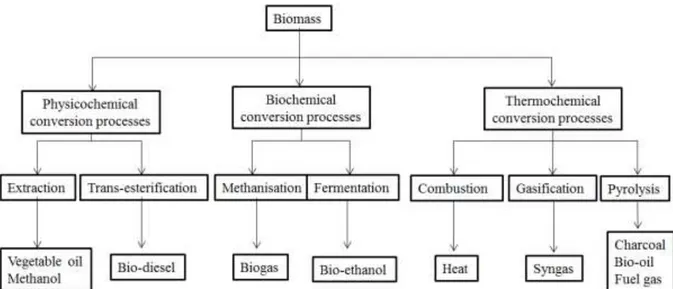
The bulky and inconvenient heterogeneous form of biomass are major barriers to a rapid shift from fossil to biomass fuels. There are many available technologies to overcome these barriers. For example, low energy density of biomass due to its high moisture content, low bulk density, high oxygen content, is dealt with pretreatment processes such as drying, densification (pelletization or briquetting) and torrefaction. In addition, various technologies aim at converting biomass into more convenient forms such as gas or liquid for transportation and use with high efficiency. These technologies can be divided into physicochemical, biochemical and thermochemical conversion processes (Figure 2).
Figure 2. Simplified illustration of the three biomass conversion pathways and their final products
I.1.3.1. Physicochemical and biochemical conversion
Physicochemical conversion includes extraction and trans-esterification. Extraction is based on the separation of useful chemical compounds with physicochemical methods such as cold press extraction, supercritical fluid extraction, and microwave extraction. In the recent years, cavitation assisted (e.g. ultrasound assisted) extraction process has been utilized for the biomass pretreatment, delignification and hydrolysis, extraction of oil, fermentation and synthesis of bioalcohol.
Trans-esterification of plant or algal oil is a standardized process by which triglycerides react with methanol in the presence of a catalyst to deliver fatty acid methyl esters and glycerol. The extracted vegetable oils or animal fats are esters of saturated and unsaturated monocarboxylic acids with the trihydric alcohol glyceride (triglycerides) which can react with alcohol in the presence of a catalyst, a process known as transesterification.
Biochemical processes includes methanisation and fermentation
Methanisation or anaerobic digestion is the natural biological process, which stabilizes organic wastes in the absence of oxygen and transforms them into bio-fertilizer and biogas. Biogas from this process mainly consists of methane (about 60 %) and carbon dioxide (approximately 40 %). Anaerobic digestion is a reliable technology for the treatment of wet organic waste. Alcoholic fermentation refers to the conversion process of biomass containing sugar or starch to obtain bioethanol (or butanol) with assistance from the enzymatic treatment. Pretreatment of the biomass is followed by enzymatic hydrolysis to produce simple sugars, fermentation of sugars to produce biofuels, and then product separation.
I.1.3.2. Thermochemical conversion
Thermochemical is an important pathway for conversion of lignocellulosic biomass into energy. The three main of processes are combustion, pyrolysis and gasification (Figure 3).
Figure 3. Details of the three types of biomass thermochemical conversion
Depending on the used amount of oxygen and on temperature, decomposition degree and/or oxidation degree are different, resulting in different products in the three processes:
- Combustion is the complete oxidation of complex hydrocarbon molecules of biomass to form carbon dioxide, water vapor. It is an exothermal process and heat releases from combustion can reach 800-1200°C. The combustion process can be used easily for heat applications, such as drying, cooking, lighting, etc... or for producing electricity.
- Gasification is the partial oxidation of biomass feedstocks under high temperature (500-1200°C) in the presence of an oxidizing agent. Oxidizing agents are typically air, steam, carbon dioxide, oxygen or a combination of them. In the presence of an oxidizing agent at high temperature, the large polymeric molecules of biomass decompose into lighter molecules and eventually to permanent gases (CO, H2, CH4 and lighter hydrocarbons), solid and liquid residues. The gaseous product from gasification process called synthesis gas or syngas can be used directly in gas engines for electricity production or upgraded into richer liquid or gas fuels. - Pyrolysis is a thermochemical decomposition of biomass molecules at moderate temperature (250-700°C) without oxidizing agent or with a limited amount of oxidizing agent. During pyrolysis, large complex hydrocarbon molecules of biomass are broken down into relatively smaller and simpler molecules in gas, liquid, and solid form. The products of pyrolysis process are used as bio-char (through carbonization process) or bio-oil (through fast pyrolysis) or in subsequent stages of gasification or combustion processes.
In addition, torrefaction and liquefaction are commonly associated to low temperature pyrolysis. Torrefaction, a process different from carbonization, is a mild pyrolysis process carried out in a temperature range of 180- 300 °C in the absence of oxygen. This thermal pretreatment of biomass improves its energy density, grindability as well as reduces its oxygen-to-carbon (O/C) ratio and hygroscopic nature. Liquefaction is the direct conversion of biomass into liquid phase at low temperatures (around 300oC), high pressures (of 200 bars) and in the presence of catalysts. This method achieves a better efficiency of the process and a good quality of the fluid produced. The main objective of these processes is to obtain a liquid with high-energy value (up to 35 MJ.kg-1) and more stable.
Despite the clear classification above, pyrolysis can occur in almost all thermochemical processes and thus it is of particular interest and the objective of this study.
I.2. Lignocellulosic biomass and thermochemical processes
I.2.1. Lignocellulosic biomass: structure, composition and properties
Biomass composition and properties have a great impact on the performance of biomass conversion processes. A proper understanding of the physical and the chemical properties of biomass feedstock is essential for the process control and optimization. This section provides different points of view on lignocellulosic biomass from biomass structural constituents of cell walls to its composition and main properties related to the thermochemical process.
I.2.1.1. Structure of lignocellulosic biomass
Biomass is a complex mixture of organic materials with small amounts of minerals such as sodium, potassium, calcium, and iron. The main components of plant biomass are fibers or
cell wall components, extractives and inorganic materials (
Figure 4). In general, lignocellulosic biomass is composed 20-60 % of cellulose, 15-40 % of hemicellulose, 10-40 % of lignin, 0-15 % of extractives and 0-20 % inorganic matters (Table 4.) [10].
Cellulose Hemicellulose Lignin Extractive Ash Softwood biomass Pinus armandii Franch 48.4 17.8 24.1 9.5 0.2 Pine 46.9 20.3 27.3 5.1 0.3 Spruce 45.6 20.0 28.2 5.9 0.3 Spruce 43.0 29.4 27.6 1.7 0.6 Fir 45.0 22.0 30.0 2.6 0.5 Japanese cedar 38.6 23.1 33.8 4.0 0.3
Eastern Red cedar 40.3 17.9 35.9 5.6 0.3
Hardwood biomass Alder 45.5 20.6 23.3 9.8 0.7 Aspen 52.7 21.7 19.5 5.7 0.3 Willow 41.7 16.7 29.3 9.7 2.5 Poplar 49.0 24.0 20.0 5.9 1.0 Cherry wood 46.0 29.0 18.0 6.3 0.5 Beech 45.0 33.0 20.0 2.0 0.2 Beech 44.2 33.5 21.8 2.6 0.5 Japanese beech 43.9 28.4 24.0 3.0 0.6
Herbaceous and agricultural biomass
Rice straw 37 16.5 13.6 13.1 19.8 Rice straw 34.5 18.4 20.2 10.1 13.3 Rice husk 37.0 23.4 24.8 3.2 17.3 Wheat straw 37.6 18.2 20.2 4.1 3.7 Corn straw 42.7 23.2 17.5 9.8 6.8 Corn leaves 26.9 13.3 15.2 22.0 11.0 Corn cob 34.6 15.2 18.2 10.6 3.5 Bamboo 39.8 19.5 20.8 6.8 1.2 Miscanthus 34.4 25.4 22.8 11.9 5.5 Switchgrass 40-45 31.35 6-12 5-11 5-6 Hazelnut shell 25.2 28.2 42.1 3.1 1.4
Table 4. The constituents of selected lignocellulosic feedstocks adapted from [10]
a. Polymer constituents
Cell walls are the major component of plants and lignocellulosic biomass, including cellulose, hemicellulose, and lignin (Figure 5). The compositions of cell walls vary widely among species, depending on the cell type or environmental conditions.
Figure 5. Spatial arrangement of cellulose hemicellulose and lignin in the cell walls of lignocellulosic biomass adapted from [11]
Cellulose
Cellulose is an organic compound with the formula (C6H10O5)n, a polysaccharide consisting of a linear chain of several hundred to many thousands of β(1→4) linked D-glucose units. It has a high degree of polymerization (up to 10,000 units of glucose) as well as strong interactions due to the numerous intra- and intermolecular hydrogen bonds, which give cellulose a crystalline structure. These characteristics give cellulose a good mechanical strength and chemical stability [11]. A representation of cellulose is given in Figure 6.
Figure 6. Structure of single cellulose molecule [11]
Lignin
Lignin, is the most complex natural polymer. Unlike cellulose, lignin has an amorphous structure with phenylpropane units as the predominant building blocks. Its composition are dependent on the species and environmental conditions prevailing during the growth of the plant. Despite its apparent complexity, lignin is mainly composed of three similar aromatic hydroxylated monomers: p-coumaryl alcohol, coniferyl alcohol and sinapyl alcohol [11]. They are presented in Figure 7.
Figure 7. Three aromatic hydroxylated monomers of lignin [11]
Hemicellulose
Hemicellulose is a heterogeneous group of branched polymers of various sugars having a large natural variability. Hemicellulose surrounds the cellulose fibers and stands as a connecting link between cellulose and lignin. Hemicellulose includes xylan, glucuronoxylan, arabinoxylan, glucomannan, and xyloglucan. Hemicellulose is composed of both hexose and pentose sugars: the C6 sugars glucose, mannose, galactose and the C5 sugars xylose and arabinose (Figure 8). The degree of polymerization of hemicelluloses is low (50 to 200). While cellulose has a hydrolysis-resistant crystalline structure, hemicellulose is amorphous due to the highly branched structure and the presence of acetyl groups connected to the polymer chain. Thus, hemicellulose is more susceptible to depolymerisation than cellulose (especially in acidic conditions) [11].
Figure 8. The hexoses and pentoses typically found in hemicellulose [12]
b. Minoritary constituents
Inorganic materials
Inorganic elements are the mineral material naturally present in plants. They represent between 0.1 and 2 % for wood, and up to more than 10 % for certain agricultural residues (Table 5). The main elements are K, Na, Ca, Mg, P and Si. They exist in the form of ions or are linked to the organic structure. During the combustion of biomass, most of the inorganic elements are found in oxidized form in the ashes.
Straw (winter wheat) Cereals (triticale) Bark (spruce) Wood chips (spruce) CaO 7.8 7.1 42.2 44.7 MgO 4.4 4.3 6.5 4.8 K2O 14.5 14.2 5.1 6.7 Na2O 0.4 0.5 0.8 0.6 P2O5 2.2 9.8 1.7 3.6
Table 5. Average concentrations of inorganic metal oxides of various biomass fuels (wt% db) [13].
Extractives
Extractives are a complex mixture of organic compounds that can be removed from the wood by solvents such as petrol ether, ether, dichloromethane, benzene, acetone, ethanol and water. They are divided into two groups: primary metabolite including low-molecular weight sugars, inositol, amino acids, simple fats and carboxylic acids and secondary such as metabolite terpenes and phenolic compounds.
I.2.1.2. Composition of lignocellulosic biomass feedstock
Lignocellulosic biomass composition are characterized by elemental and proximate analyses. Table 6 shows the composition of various biomass types.
Biomass
Proximate analysis, % db Ultimate analysis, % daf HHV
Ash VM FC C H N S O MJ/kg (db) Beech 0.60 84.87 14.53 49.68 6.21 0.28 0.01 43.81 19.32 Birch 0.20 94.73 5.07 47.7 6.01 0.1 0.03 45.59 18.21 Poplar 1.22 85.07 13.71 50.03 6.07 0.23 0.05 43.6 19.50 Fir 2.20 84.80 13.00 51.53 5.93 0.1 0.10 42.02 20.05 Oak 1.40 85.60 13.00 49.67 6.13 0.15 0.02 44.10 18.65 Spruce 0.20 89.60 10.20 47.40 6.30 0.07 0.00 46.20 19.30 Pine 0.35 83.83 15.82 53.15 6.20 0.13 0.24 40.26 20.71 Wheat straw 8.24 75.54 16.22 49.06 6.17 1.00 0.2 43.29 17.68 Corn stover 5.06 80.86 14.08 49.31 6.04 0.70 0.11 43.56 18.10 Rice husk 20.60 54.40 25.00 39.60 6.00 0.70 0.00 53.70 13.40 Rice straw 20.15 65.62 14.23 49.15 6.23 1.59 0.13 42.13 14.74 Miscanthus 2.73 91.70 5.57 49.66 6.07 0.59 0.11 43.39 19.31 Switchgrass 5.40 81.50 13.10 50.74 5.71 0.49 0.17 43.76 17.61 MSW 56.00 18.00 26.00 57.27 3.64 1.36 5.00 42.27 8.18 Sewage sludge 49.70 44.15 6.15 52.70 8.15 6.28 2.21 30.72 11.44 Cattle manure 41.60 47.30 11.10 56.42 8.39 1.18 1.34 29.93 15.12 Table 6. Typical proximate (db, %) and ultimate analyses % (daf) and higher heating values for
various biomass types [14]
a. Elemental analysis
From the elemental point of view, biomass is essentially composed of carbon, oxygen, hydrogen, nitrogen, sulfur and a low content of inorganic compounds. These elemental composition are provided by the elemental or ultimate analysis. The elemental composition results can be illustrated by Van Krevelen diagram, which cross-plot the hydrogen: carbon atomic ratios as a function of the oxygen: carbon atomic ratios of organic materials. This diagram provides a comparison between biomass and other fuels as well as between different biomass feedstocks (Figure 9).
Figure 9. Van Krevelen diagram for various solid fuels
In many applications at high temperature, the elemental analysis is important in evaluating feedstocks with regarding potential pollution concerns. Nitrogen content in biomass is carefully paid attention as it shows the potential of pollution by formation of nitrogen oxide (NOx) during conversion. Moreover, in some biomass materials such as municipal solid waste and animal waste, the determination of chlorine and sulfur is particularly important because it shows possible pollutants and corrosive agents to gasification and combustion system.
b. Proximate analysis
Proximate analysis provides the amount of moisture, volatile matter, ash, and fixed carbon of biomass samples.
Moisture
The moisture in biomass can remain in two forms: (i) free or external and (ii) inherent. Free moisture is that above the equilibrium moisture content. It generally resides outside the cell walls. Inherent moisture, on the other hand, is absorbed within the cell walls. When the walls are completely saturated, the biomass is said to have reached the fiber saturation point, or equilibrium moisture. Equilibrium moisture content is a function of the relative humidity and temperature. High moisture content results in low net energy content in biomass feedstocks. Thus, moisture content affects the logistics system (scale and cost) such as storage, handling and transport. In addition, moisture content must be driven off before the oxidation reactions of the hydrocarbon of biomass can start. It requires a significant energy to evaporate and thus can reduce the conversion efficiency.
Volatile matter
The volatile matter of a fuel is the condensable and non-condensable vapors released when the fuel is heated to moderate temperatures, above about 150°C. The quantity of volatile depends on the type and origin of biomass (Table 6). In general, volatile matter content in biomass is higher than that in coal.
Ash
Ash is the inorganic solid residue left after the fuel is completely burned. Its primary ingredients are silica, potassium, aluminum, iron, and calcium; small amounts of magnesium, sodium, and titanium maybe present. Ash is the important parameter to estimate the potential risk of slagging and fouling issues during biomass combustion or gasification. Slagging and fouling are the problems that occur when the ash begins to melt, causing deposits inside the combustion equipment. Under some conditions, the combustion ash can partially melt, forming deposits on the combustor surfaces (fouling) or hard chunks of material in the base of the combustion chamber (slagging/clinkering). Certain mineral components in biomass fuels, primarily silica, potassium, and chlorine, can cause these problems to occur at lower temperatures than might be expected. However, some alkaline metals have a positive impact on the biomass thermochemical process as they act as catalysts.
Ash content depends on the origin of biomass. In general, the ash content of herbaceous biomass is higher than that of woody biomass. Ash weight content in herbaceous biomass is in range from less than 2 % up to 10 % or even up to 20 % for rice husks while that is around 1 % for woody biomass. In waste fractions, the ash content may often be as high as 30-50 % and is only scarcely less than 10 % (Table 6).
Fixed carbon
Fixed carbon is the solid combustible residue that remains after biomass is heated and the volatile matter is released. Thus, fixed carbon content in biomass is calculated value, which is determined from the following equation:
FC = 1- M - A -VM (1)
Where FC, M, A and VM are the fixed carbon, moisture, ash and volatile matter contents in biomass on the same basis of analysis.
c. Summary of expressing biomass composition
In practice, there are four types of bases of analysis commonly used for expressing biomass analysis results, i.e., as-received basis, air-dried basis, dry basis, and dry ash-free basis (Figure 10).
Figure 10. Bases of expressing biomass composition [15]
As-received basis is the mean of expressing an analytical result based on the total weight of
sample as it arrived at the laboratory and prior to any pre-treatment.
Air-dried basis is the means of expressing an analytical result based on the condition in which
the sample is in equilibrium with atmospheric humidity. Air-dried basis neglects the presence of moisture other than inherent moisture.
Dry basis (db) is the means of expressing an analytical result based on the condition in which
biomass is free from moisture. Dry basis leaves all moistures including external and inherent moistures.
Dry ash-free (daf) basis is the means of expressing an analytical result based on a condition
in which the sample is considered to be free from both all moistures and ash. This is frequently used in ultimate analysis to show the contents of elements in the organic fractions of the biomass sample.
d. Energy content
Results of ultimate and proximate analysis allow the calculation of an important characteristic of a fuel, energy content. Energy content of biomass indicates the amount of energy stored in a given unit of a biomass sample. It is measured as the heat of combustion, which is the total energy released as heat when it undergoes complete combustion with oxygen under standard
conditions. Calorific value (or heating value) is common used to express the energy content. There are two types of heating value: higher heating value and lower heating value.
Higher heating value (HHV) is defined as the amount of heat released by the unit mass or volume of fuel (initially at 25 °C) once it is combusted and the products have returned to a temperature of 25 °C. It includes the latent heat of vaporization of water.
Higher heating value can be measured by a bomb calorimeter or can be estimated from the results of the ultimate and proximate analysis following the equation of Chaniwala and Parikh [16].
HHV= 0.3491C + 1.1783H - 0.10S - 0.0134O - 0.0151N - 0.0211A (2) This correlation is valid within the range:
0 < C < 92 %; 0.43 < H < 25 % 0 < O < 50 %; 0 < N < 5.6 % 0 < A < 71 %;
4745 < HHV < 55,345 kJ.kg-1
Lower heating value (LHV), also known as the net calorific value, is defined as the amount of heat released by fully combusting a specified quantity less the heat of vaporization of the water in the combustion product.
The relationship between HHV and LHV is given by:
𝐿𝐻𝑉 = 𝐻𝐻𝑉 − ℎ𝑔( 9𝐻 100+
𝑀
100) (3) where LHV, HHV, H, and M are lower heating value, higher heating value, hydrogen percentage, and moisture percentage, respectively, on an as-received basis. Here, hg is the latent heat of water 2260 kJ.kg-1.
I.2.1.3. Properties of lignocellulosic biomass
a. Physical properties
Granulometry
Woody and herbaceous biomasses are of irregular shapes. Shape and size of biomass feedstocks affect the flow behavior in transport and storage system and surface area for heat and mass transfers. The feedstock is usually pretreated to meet the requirement of different
thermochemical conversion technologies. For example, fast pyrolysis requires biomass with smaller particle size than slow pyrolysis. For that, grindability can be considered as one of the important properties of biomass. The grindability of a material is a measure of its resistance to grinding. The lignocellulosic components of biomass, especially cellulose and lignin, are very fibrous and difficult to grind. The grindability of biomass can be greatly improved due to increased brittleness and a reduction of the cellulose fiber length through torrefaction.
Density
There are three types of density: true density, apparent density and bulk density.
True density is defined as the ratio of total mass of biomass to the solid volume in biomass. It is measured with a Helium pycnometer.
Apparent particle density is defined as the ratio of total mass of biomass to the volume of the particle (solid and internal pores). Apparent volume can be calculated from the measurement of the main dimension (diameter, side) using a micrometer.
Bulk density is the ratio of the mass of a stock of biomass particles to the total volume occupied by particles, thus including the pore space volume between and within the biomass particles. Bulk density is a key physical property in designing the logistics system for biomass handling and transport. It depends on the biomass particle size and shape, moisture content, particle density, and surface characteristics. Table 7 shows the bulk densities of several biomass feedstocks.
Fuel Characteristic dimension (m) Bulk density (kg.m-3)
Sawdust 0.0003-0.002 300
Chopped straw 0.005-0.025 60
Green wood chips 0.025-0.075 500
Wood pellets 0.006-0.008 600
Biomass briquettes 0.025-0.01 600
Cordwood 0.3-0.5 400
Table 7. Typical size and density of several biomass fuels
b. Thermochemical properties
This section presents several important thermodynamic properties of biomass that influences thermochemical conversion.
Thermal conductivity
When a solid particle is heated in thermochemical conversion processes, it is subjected to heat conduction along and across its fiber, which in turn influences its thermochemical conversion behavior. Thus, the thermal conductivity of the biomass is an important parameter in this context. Di Blasi [17] reported in her extensive review on wood and biomass pyrolysis modeling that density and thermal conductivity cause the highest sensitivity of the model predictions.
Several works on thermal conductivity can be found in literature thanks to the literature survey of Hankanin et al [18]. Most studies on thermal conductivity focus on wood as a common biomass. They showed that wood is an anisotropic material, and its thermal conductivity depends on heating direction, moisture, porosity, density and temperature. In detail, Harada et al. [19] developed the following correlation for wood thermal conductivity based on their flash method experiments at a temperature range of 293 – 513 K.
𝜆𝑤 = 0.00249 + 0.000145 𝜌𝑤 0.000184 (T − 273) (4) where 𝜆𝑤 is wood thermal conductivity, 𝜌𝑤 density and T temperature in K. The correlation indicates that thermal conductivity is linearly proportional to temperature and increases 50 % at a temperature range of 293 – 513 K.
Another correlation from Koufopanos et al. [20] is also commonly used in literature:
𝜆𝑤 = 0.13 + 0.0003 (T − 273) (5)
Specific heat
Specific heat, an indication of the heat capacity of a material, is another important thermal property of biomass, required for thermodynamic calculations. It depends on the moisture content of biomass and temperature.
Within the temperature range of 0 to 106 °C, the specific heat of a large number of wood species (dry) can be expressed as (Jenkins [21]):
𝐶𝑝θ= 0.266 + 0.00116θ (6)
where temperature θ is in °C.
𝐶𝑝 = 𝑀𝑤𝑒𝑡𝐶𝑤𝑒𝑡 + (1 − 𝑀𝑤𝑒𝑡)𝐶𝑝θ (7) where 𝑀𝑤𝑒𝑡 is the moisture fraction on a wet basis, and 𝐶𝑤𝑒𝑡 is the specific heat of water. Recently, Dupont et al. [22] correlated the relationship between the specific heat and temperature of 21 biomass types including wood, agricultural residue and energy crop samples with particle size below 200 µm.
𝑐𝑝𝑇 = 5.34 𝑇 − 299 (8)
Standard Enthalpy of Formation
Standard Enthalpy of Formation is the enthalpy change when one mole of compound is formed at standard state (25 °C, 1 atm) from its constituting elements in their standard state. All elements in their standard states have a standard enthalpy of formation of zero, because there is no change involved when they are formed from themselves. For example, hydrogen and oxygen are stable in their elemental form, so their enthalpy of formation is zero. If the compound is formed through multiple steps, the standard enthalpy is the sum of the enthalpy change in each process step. Table 8 shows the standard enthalpies of some common compounds.
Compound H2O CO2 CO CH4 O2 CaCO3 NH3
Standard enthalpy of
formation at 25°C (KJ.mol-1) -241.5 -393.5 -110.6 -74.8 0 -1211.8 -82.5
Table 8. Standard enthalpy of formation of some common compounds [23]
Enthalpy of Reaction
Enthalpy of Reaction is the amount of heat released or absorbed in a chemical reaction with no change in temperature. In the context of combustion reactions, it is called heat of combustion, ΔHcomb, which can be calculated from the standard enthalpy of formation (SEF) as:
ΔHcomb = [Sum of SEF of all products]- [Sum of SEF of all reactants] (9) The ΔHcomb for a fuel is also defined as the enthalpy change for the combustion reaction when balanced:
Self-Ignition Temperature
Self-Ignition Temperature (SIT) is an important property of any fuel because it shows that the combustion reaction of the fuel becomes self-sustaining only when temperature reaches a value above it. In a typical gasifier, a certain amount of combustion is necessary to provide the energy required for drying and pyrolysis and finally for the endothermic gasification reaction. In this context, it is important to have some information on the ignition characteristics of the fuel. However, SIT is not a unique property of a fuel. It depends on several other factors like oxygen partial pressure, particle size, rate of heating, and particle’s thermal surroundings. Table 9 shows the SIT of some common biomass feedstocks.
Sample Volume in cm3 SIT in °C
Wood chips 100 210 Wood chips 200 204 Wood chips 400 196 Wood chips 800 188 Wood pellets 100 184 Wood pellets 200 180 Wood pellets 400 172 Wood pellets 800 168 Wood briquettes 200 180 Wood briquettes 400 176 Waste wood 400 188 Waste wood 800 176 Waste wood 1600 176
Table 9. Self-ignition temperature (SIT) of several biomass feedstocks [24]
I.2.2. Thermochemical conversion processes
Before going into the details for each process, we analyze an example of the conversion process efficiencies when converting one ton of a dried wood into heat and then electricity through combustion, carbonization and gasification (Figure 11).
Figure 11. Quantity of thermal and electricity energies from wood conversion via different thermochemical processes [25].
The results presented in Figure 11 propose, in the technical point of view, that: - for heat production purposes, direct combustion of wood is the best solution;
- for electricity production purpose, gasification shows the highest efficiency, followed by two other pathways: carbonization-gasification and combustion-steam engine. Thus, the choice of thermochemical processes depends on the usage purpose and levels of the technology development.
The following sections detail these technologies.
I.2.2.1. Combustion technologies
Combustion is the most common and the oldest use of biomass. It covers a wide range of applications, including:
- Domestic use for cooking and heating by various stove and boiler systems.
- Waste treatment such as incineration for municipal solid waste or cleaning and preparing agricultural land by burning wastes and by-products.
In principle, combustion technologies can be classified into fixed bed combustion, fluidized bed combustion, pulverized fuel combustion [26] (Figure 12).
Figure 12. Overview of different combustion technologies [26]
Fixed bed combustion includes grate furnaces and underfeed stokers. Primary air passes through a fixed bed, in which drying, gasification and charcoal combustion take place. The combustible gases are burnt after secondary air injection. Fixed bed combustion system has a large flexibility concerning moisture content (10-60 %) and particle size (5 mm-10 cm). The capacity of this type of combustion technology is between 10 kW to 50 MW.
Within a fluidised bed reactor, biomass fuel is burnt in suspension of gas and solid bed materials. Depending on the fluidisation velocity, there are two kinds of fluidised bed combustion: bubbling fluidised bed and circulating fluidised bed combustion. Fluidised bed furnaces offer a large flexibility concerning moisture content (10-55 %) and fuel mixing, but a low flexibility concerning particle size (<80 mm). The boiler capacity range covers 20 MW to several hundred MW.
Pulverized fuel combustion is suitable for fuels with small particle size. A mixture of fuel and primary combustion air is injected into the combustion chamber. Combustion takes place while the fuel is in suspension and gas burnout is achieved after secondary air addition. The moisture content is usually below 20 % and particle size is limited up to 20 mm. The boiler capacity ranges from 500 kW to several hundred MW (for co-firing systems).
- Small-scale biomass combustion systems: capacity range <100 kWth.
- Medium-scale combustion systems: capacity range from 100 kWth to 20 MWth. - Large-scale combustion systems: capacity range > 20 MWth.
- Co-firing of biomass in coal fired power stations: capacity range several 100 MWth.
Figure 13. Wood pellets are metered directly on a coal conveyor before the mills at Wallerawang Power Station, Australia [27]
Figure 13 shows an example of co-firing of biomass in coal-fired power station.
In addition, combustion technologies can be also classified based on the application domains or type of feedstocks (Table 10).
Combustion systems (Capacity ) Small-scale <100 kWth Medium-scale 100 kWth to 20 MWth Large-scale > 20 MWth Co-firing Several 100 MWth Applications Residential heating District heating Process heating and cooling CHP production CHP production Power production CHP production Power production Biomass feedstocks Log wood Wood pellets Wood pellets Wood pellets Bark Forest residues Waste food Straw Bark Forest residues Domestic wastes Straw Fruit stones, kernels, husks, shells Forest residues Sawdust Wood pellets Wood pellets Straw Fruit stones, kernels,
husks, shells Technologies Wood stoves Fire-place inserts Heat storing stoves Wood boilers Underfeed stokers Grate-fired systems Dust burners Grate-fired systems Fluidized beds Co-firing of finely milled biomass mingled with coal Biomass co-firing in
fluidized bed combustion systems Co-firing in separate combustion units and junction of steam Biomass gasification and utilization of the product gas as fuel in a coal combustion
system
Table 10. Application domains, feedstocks and available technologies for the combustion systems [28]
I.2.2.2. Gasification technologies
Gasification converts biomass into convenient gaseous fuels, along with liquid residues (condensates) and a solid residue (char). Produced gas from the biomass gasification can be used in gas turbine, gas burner, fuel cell, or in CHP (Combined Heat and Power) systems. Technologies for biomass gasification can be classified into three main categories: fixed bed; fluidized bed and entrained flow gasifiers. Their specification are listed in Table 11.
Reactor type Fixed bed Fluidized bed Entrained flow
Power < 5MWth > 10 MWth > 20 MWth
Particle sizes > 1 cm 1-80 mm < 1 mm
Water content < 20 % 10-40 % < 15 %
Temperature 120-1200°C 800-900°C > 1300°C
Heating rate low very high high
Solid residence time > 1h < 1 min < 1s
Gas residence time > 2s < 2s < 1s
Application Cogeneration Cogeneration,
Methanation
Methanation, Hydrogen Fisher Tropsh
synthesis Table 11. Typical conditions in biomass gasifiers [29]
a. Fixed bed gasifiers
There are many types of fixed bed reactors, but they can be grouped into updraft, downdraft, and multi-staged gasifiers.
Updraft gasifiers are characterized by an upward gas flow inside the reactor. Biomass is fed from the top while air is introduced from the bottom (Figure 14). Gas is produced in a high temperature zone close to the grate, travels up to cooler zone of pyrolysis and drying of biomass and then leaves out from the top of the reactor. The produced gas accompanied with tar (condensates) travels upward through cooler regions and therefore has no opportunity for conversion into gases and secondary tar. For this reason, updraft gasifiers generate the highest amount of tar compared to other fixed bed gasifier types, typically 10 to 20 % by weight of the initial feedstock.
Figure 14. Updraft gasifier configuration and temperature profile [15]
In downdraft gasifiers, the pyrolysis zone is above the combustion zone and the reduction zone is below the combustion zone (Figure 15). Fuel and gas travel downward. Tar and gas produced in the pyrolysis zone pass through the highest temperature zones: combustion and reduction zones. Thus, this configuration allows the tar cracking easily, resulting in a very low tar production (<1 g.Nm-3).
Multi-staged gasifier include two-staged gasifiers or three-staged gasifiers such as the NOTAR® reactor developed by Xylowatt® or the Viking gasifier developed by the DTU (Danish Technical University).
Here, we introduce a typical example of the two-staged fixed bed gasifier, the NOTAR® (300 kWe or 600 kWth) (Figure 16), previously described in [29].
Figure 16. The staged fixed bed gasifier NOTAR® developed by Xylowatt®
This type of gasifier allows the separation of the different stages in a gasification process: - The pyrolysis of biomass takes place in a fixed bed reactor. Biomass and air are fed into
the first reactor on top. Partial oxidation of biomass and the pyrolysis products allows the autothermal operation and temperature can reach 500-700°C. A reaction zone in the first reactor of pyrolysis, which produces char, volatile matters and tends to propagate upward, is maintained stable by extracting char from this reactor to the second reactor of gasification.
- The volatile pyrolysis products are passed into the second reactor where they are oxidized (and/or cracked) by adding the secondary air injection. A part of the produced char from the first reactor can also be oxidized here. Temperature in this combustion zone can reach about 1200 °C.
- The gasification of the char takes place in a second reactor downstream of the combustion zone, at a temperature of about 1000 °C. The synthesis gas leaves the reactor at about 700 °C.
b. Fluidized bed gasifiers
In a typical fluidized bed (bubbling or circulating) air enters from the bottom, but fuel is fed from its sides or top (Figure 17).
Figure 17. Schematic diagram of (a) bubbling fluidized bed gasifier and (b) circulating fluidized bed gasifier [15]
In a bubbling fluidized bed gasifier, when the gas velocity is increased (1-2 m.s-1), a situation is reached when the particles are suspended by the upward flowing gas. Gas moves through the bed in voids and in bubbles with higher velocity. Particles are entrained into the freeboard along with these fast moving bubbles. Some fine particles are transported with the produced gas and leave the reactor at the top. However, most of the entrained particles fall back and can be continuously removed from the fluidized bed with the remaining ash at the bottom. A uniform temperature zone can be reached. The produced gas can be characterized by high particulate loadings and medium tar contents [15].
In a circulating fluidized bed gasifier, when the gas velocity is increased beyond the bubbling fluidized bed regime (5-10 m/s), the solid is distributed across the whole volume and entrained by the gas at the top of the gasifier. Particles are separated from the gas in a cyclone and are returned to the fluid bed near the bottom. This configuration allows a longer overall residence time. Circulating fluidized bed gasifiers are normally used for large applications. It has enhanced flexibility over bubbling fluidized bed gasifier for firing multi-fuels with high moisture content and significantly higher efficiency [15].
c. Entrained flow gasifier
Entrained flow gasifier (Figure 18) requires a very small biomass particle such as dust fuels or slurry. It works at high temperatures (>1200°C) and the gasification reactions end within a few
![Figure 11. Quantity of thermal and electricity energies from wood conversion via different thermochemical processes [25]](https://thumb-eu.123doks.com/thumbv2/123doknet/14043943.459345/42.892.116.785.104.616/figure-quantity-electricity-energies-conversion-different-thermochemical-processes.webp)
![Figure 26. Relative composition of pyrolysis oils by tar class as a function of cracking temperature [51]](https://thumb-eu.123doks.com/thumbv2/123doknet/14043943.459345/66.892.227.676.113.367/figure-relative-composition-pyrolysis-class-function-cracking-temperature.webp)
![Figure 36. Reaction zone thickness inside the bed as a function of moisture content in the fuel [79]](https://thumb-eu.123doks.com/thumbv2/123doknet/14043943.459345/74.892.221.689.634.922/figure-reaction-zone-thickness-inside-function-moisture-content.webp)
![Figure 37. Distribution of pyrolysis products; yields are calculated on the basis of dry wood chips [59]](https://thumb-eu.123doks.com/thumbv2/123doknet/14043943.459345/75.892.208.685.418.715/figure-distribution-pyrolysis-products-yields-calculated-basis-chips.webp)
![Figure 38. Product distribution of pinewood 500 °C pyrolysis under different oxygen concentrations [77]](https://thumb-eu.123doks.com/thumbv2/123doknet/14043943.459345/76.892.241.663.107.455/figure-product-distribution-pinewood-pyrolysis-different-oxygen-concentrations.webp)