HAL Id: tel-01729093
https://tel.archives-ouvertes.fr/tel-01729093
Submitted on 12 Mar 2018HAL is a multi-disciplinary open access archive for the deposit and dissemination of sci-entific research documents, whether they are pub-lished or not. The documents may come from teaching and research institutions in France or abroad, or from public or private research centers.
L’archive ouverte pluridisciplinaire HAL, est destinée au dépôt et à la diffusion de documents scientifiques de niveau recherche, publiés ou non, émanant des établissements d’enseignement et de recherche français ou étrangers, des laboratoires publics ou privés.
Effect of the support on the activity and morphology of
hydrodesulfurization catalysts
Elizabeth Dominguez Garcia
To cite this version:
Elizabeth Dominguez Garcia. Effect of the support on the activity and morphology of
hydrodesulfurization catalysts. Organic chemistry. Normandie Université, 2017. English. �NNT : 2017NORMC258�. �tel-01729093�
THESE
Pour obtenir le diplôme de doctorat
Spécialité CHIMIE
Préparée au sein de l’ENSICAEN et de l’UNICAEN
EFFECT OF THE SUPPORT ON THE ACTIVITY AND MORPHOLOGY OF
HYDRODESULFURIZATION CATALYSTS
Présentée et soutenue par
Elizabeth DOMINGUEZ GARCIA
Thèse dirigée par Laetitia OLIVIERO et Françoise MAUGÉ, Laboratoire Catalyse et Spectrochimie (LCS)
Thèse soutenue publiquement le 19 Décembre 2017 devant le jury composé de
M. Fréderic RICHARD Maître de Conférences, HDR / Université de Poitiers Rapporteur
M. Jeppe V. LAURITSEN Professeur / Université d’Aarhus / Danemark Rapporteur
Mme. Barbara GARCIA PAWELEC Directrice de recherche / Université de Madrid Rapporteur
Mme. Carole LAMONIER Professeur des Universités / Université de Lille Examinateur
M. Arnaud TRAVERT Professeur des Universités / Université Caen Normandie Examinateur
Mme. Françoise MAUGË Directrice de recherche CNRS / Université Caen Normandie Codirecteur de thèse
“All geniuses are crazy but not all crazies are geniuses”
Acknowledgement
This section is dedicated to all people who in one or another way have been part of this long journey.
Firstly, I would like to thank my supervisors, Dr. Laetitia Oliviero and Dr. Françoise Maugé for giving me this great opportunity that has made me grow professionally and personally. I would also like to thank Dr. Jianjun Chen and Luz Zavala. Next, I would like to thank the members of the jury, Dr. Fréderic Richard, Dr. Carole Lamonier, Dr. Jeppe V. Lauritsen, Dr. Arnaud Travert and Dr. Bárbara Garcia Pawelec for agreeing to be participants of this moment.
Secondly, I would like to thank all LCS members where I have spent these three years. And especially I would like to thank those people who have been like my family during my stay in Caen, the members of the "Trappist team". Shashu, Juju, Dudu, Eddu, Kaka and of course my Paloma. Thanks to them, I did not feel alone being so far from my loved ones. Also I would like to thank Gitana because he was standing with me in the craziest moment and Stijn for the great moments on sulfur room.
Thirdly, I would like to thank all those people who have strongly influenced my professional life before the thesis. Dr. José Antonio Odriozola, Dr. Francisca Romero, Dr. Maribel Dominguez and Dr. Svetlana Ivannova. They do chemistry in a special way. Of course, I did not forget Dr. Cecilio Carreras. Finally I would like to thank some of the people, who unknowingly influenced me and thanks to their chemistry devotion, I started this long journey thanks to you, Federico Habela.
And finally, but not less extent, I would like to thank my family for their support and unconditional love during these three years and throughout our lives. Especially I would like to thank my parents for the education they taught me. Thanks to that I have overcome all the obstacles that have arisen along the way and will be presented in the future. Last but not least, I wanted to thank Manuel, for his great support, understanding and affection throughout all this time. And, Isabel Rodriguez who is always there for me.
Esta sección de la memoria va dedicada a todas aquellas personas que, de una u otra manera, han formado parte de este largo camino.
En primer lugar, me gustaría agradecer a mis directoras de tesis, Dra. Laetitia Oliviero y Dra. Françoise Maugé por darme esta gran oportunidad que me ha hecho crecer profesional y personalmente. También me gustaría agradecer al Dr. Jianjun Chen y a Luz Zavala. Seguidamente, me gustaría agradecer a los miembros del tribunal, Dr. Fréderic Richard, Dra. Carole Lamonier, Dr. Jeppe V. Lauritsen, Dr. Arnaud Travert y Dra. Bárbara Garcia Pawelec por aceptar ser partícipes de este momento.
En Segundo lugar, me gustaría agradecer a todos los miembros del LCS dónde he pasado estos tres años. Y especialmente a aquellas personas que han sido como mi familia durante mi estancia en Caen, los miembros del “Trappist team”. Shashu, Juju, Dudu, Eddu, Kaka y por supuesto mi Paloma. Ellos han hecho que no me sintiera sola estando tan lejos de mis seres queridos. También me gustaría agradecer a Rafa por soportarme incluso cuando estaba rozando la locura y a Stijn por los grandes momentos vividos en “sulfur room”.
En tercer lugar, me gustaría agradecer a todas aquellas personas que han influido fuertemente en mi vida profesional antes del doctorado. Dr. José Antonio Odriozola, Dra. Francisca Romero, Dra. Maribel Domínguez y Dra. Svetlana Ivanova. Ellos hacen química de una forma especial. Por supuesto al Dr. Cecilio Carreras en la que su pasión por la enseñanza hizo que realmente disfrutara trabajando. Por último, me gustaría agradecer a unas de las personas, que sin saberlo, más me influyó y que gracias a su devoción por la química hizo que comenzara este largo camino, Federico Habela.
Y finalmente, pero no en menor medida, me gustaría agradecer a mi familia por su apoyo y amor incondicional durante estos tres años y toda la vida. Especialmente me gustaría agradecer a mis padres por la educación que me inculcaron, gracias a ello he sabido superar todos los obstáculos que se han presentado en mi vida. Y finalmente, quería darle las gracias a Manuel, por su gran apoyo, comprensión y cariño a lo largo de todo este tiempo. Y a Isabel Rodríguez quien siempre ha confiado que conseguiría todas mis metas.
Table of contents
General Introduction ... 1
Chapter I: INTRODUCTION ... 9
Chapter II: CHARACTERIZATION TECHNIQUES ... 39
Chapter III: SUPPORT EFFECT ON NON-PROMOTED CATALYSTS .... 69
Chapter IV: SUPPORT EFFECT ON PROMOTED CATALYSTS ... 113
Chapter V: METAL LOADING EFFECT ON NON- AND PROMOTED
CATALYSTS USING SILICA AS SUPPORT ... 151
Chapter VI: DRYING AND CALCINATION EFFECT ON THE
STRUCTURE AND ACTIVITY OF SULFIDE (Co)Mo CATALYTS ... 189
Annex I: SUPPORTED DATA FOR SUPPORT EFFECT ON
NON-PROMOTED CATALYSTS ... 219
Annex II: Mo LOADING EFFECT ON HDS CATALYSTS SUPPORTED ON
MCM-41 AND TOF CALCULATIONS FOR Mo/SiO
2CATALYSTS ... 227
Annex III: EFFECT OF Mo LOADING AND TITANIA STRUCTURE ON
THE MoS
2MORPHOLOGY OF Mo/TiO
2CATALYSTS ... 245
Annex IV: DECOMPOSITION ... 261
1
General introduction
Nowadays, a lot of efforts are put into the development of energy with low environmental impact. The energy sources can be classified into renewable as solar, hydraulic, wind or biomass and non-renewable as nuclear and fossil (coal, oil and natural gas). The fossil fuel is still the most largely used currently, since it constitutes around 87% of the total energy consumed in the world [1]. Although crude oil contains the same principal components i.e. hydrocarbons and to a lesser extent, heterocompounds (sulfur, nitrogen, oxide compounds…) and metals (Table 1), it can present different characteristics depending of its geographic origin.
Table 1. Elements in crude oil [2]
Element in fuel Percentage in wt%
Carbon 82 – 87
Hydrogen 12 – 15
Sulfur 0.1 - 5.5
Nitrogen 0.1 - 1.1
Oxygen 0.1 - 4.5
Crude oil can be classified into light or heavy oil following some important properties such as (i) API gravity (inverse of density) which is thus directly linked with the density of the crudes and (ii) sulfur percentage, since a greater amount of heterocompound is found in heavy oils.
Table 2. Properties of crude oils (API and sulfur amount) [10]
Crude oil class Property Range
Gravity (ºAPI) Sulfur (wt. %)
Light 35-60 > 0.5
Medium 26-35 > 1.1
2 The negative impact on environment of fuel combustion is a very big concern. In addition to global warming due to CO2 release, emissions of particles and toxic gases as NOx
and SOx lead also to drastic consequences on air quality, human health and environmental
preservation. Hence, in most of the countries, governments implement or make more drastic the regulations as the regulations for the sulfur amount in land transportation fuel. Regulations of the sulfur amount in the sea transportation fuel will be also implemented in the coming years.
Hence, improvement of hydrotreatment processes as hydrodesulfurization (HDS), hydrodenitrogenation (HDN), hydrodeoxygenation (HDO), and hydrodemetallization (HDM), that are the main process for removal of sulfur, nitrogen, oxygen and metal, are of crucial importance. Conventional hydrotreatment catalysts are formed by molybdenum sulfide supported on alumina carrier with cobalt or nickel added as promoter. Nowadays, considering that crude oil tend to get heavier and heavier, meaning that the heterocompound containing molecules are bigger and bigger and thus more refractory, research is going on to still improve the hydrotreating catalyst activity. Thus, understanding the formation of active sites, their structures as well as their role in the reaction is necessary.
The present PhD thesis deals with a deep molecular insight into oxidic and sulfided phase of hydrotreatment catalyst. In this work, a special effort was made to understand the factors that affect the sulfided phase morphology and the consequence of the morphological changes on the catalytic activity. The main parameters we analyzed are:
- the influence of the support nature - Mo and CoMo catalysts deposited on alumina, silica and titania with a constant Mo and Co coverage were studied in Chapter III and IV
- the effect of Mo and Co loading on silica (Chapter V and Annex II), and titania (Annex III)
- the effect of pretreatment as drying and calcination, on sulfided catalysts supported on silica, alumina and titania (Chapter VI)
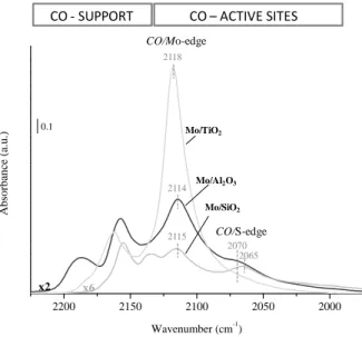
In this work, the catalysts are deeply (but not exclusively) characterized by CO adsorption at about 100K followed by FTIR spectroscopy (IR/CO). Indeed, it was previously shown that IR/CO is a very powerful tool that accounts for the nature, the amount of sulfided sites as well as their structure (M-edge or S-edge, sulfur coordination) and thus account for
3 the morphology of sulfided phase. Parallel were done between spectroscopic data and thiophene HDS activity.
References
[1] Http://euanmearns.com/global-energy-trends-bp-statistical-review-2014/, (n.d.). [2] A. Strahler, Physical Geology, Omega, Barcelona, 1992.
[3] A. Stanislaus, A. Marafi, M.S. Rana, Catal. Today 153 (2010) 1–68. [4] I. V Babich, J.A. Moulijn, Fuel 82 (2003) 607–631.
[5] S. Brunet, D. Mey, G. Perot, C. Bouchy, F. Diehl, Appl. Catal. a-General 278 (2005) 143–172.
[6] P. Grange, X. Vanhaeren, Catal. Today 36 (1997) 375–391. [7] I. Mochida, K.H. Choi, J. Japan Pet. Inst. 47 (2004) 145–163. [8] C.S. Song, Catal. Today 86 (2003) 211–263.
[9] H. Topsoe, B.S. Clausen, N.Y. Topsoee, E. Pedersen, Ind. Eng. Chem. Fundam. 25 (1986) 25–36.
5
Table of contents – I Chapter
I. CHAPTER ... 7
1.1 Hydrodesulfurization catalysts ... 8
1.1.1 Active sites on HDS non-promoted catalysts ... 10
1.1.1.1 MoS2 structure ... 10
1.1.1.2 MoS2 morphology ... 11
1.1.2. Active sites on HDS promoted catalysts ... 15
1.1.2.1 Co promotion: CoMoS morphology ... 17
1.1.3. Support effect in HDS catalysts ... 19
1.1.3.1. Anchorage nature on support surface ... 20
1.1.3.1.1. Aluminum oxide (ϒ-Al2O3)... 20
1.1.3.1.2. Silicon oxide (SiO2- silica gel) ... 21
1.1.3.1.3. Titanium oxide (anatase- and rutile-TiO2 phases) ... 22
1.1.3.2. Anchorage mode ... 23
1.1.3.3. Support effect on the MoS2 morphology ... 24
1.1.3.4. Support effect on the activity ... 25
1.2 Hydrodesulfurization model reactions ... 26
1.2.1 Mechanism of hydrodesulfurization of Thiophene ... 27
1.2.2 Mechanism of hydrodesulfurization of Dibenzothiophene ... 28
1.3 Scope of the thesis ... 29
I. CHAPTER
INTRODUCTION
I. Chapter. Introduction
8
1.1 Hydrodesulfurization catalysts
Typical hydrodesulfurization (HDS) catalysts are formed by transition metal sulfide (molybdenum or tungsten) supported on alumina and promoted by a second metal, normally cobalt, nickel or both together to improve the catalytic activity. The conventional preparation procedure for Co-promoted HDS catalyst supported on alumina may be divided in two different stages as shows Figure I.1: metal oxide dispersion on the support surface and the oxide species transformation to sulfide species. The metal deposition on the support surface normally is performed by wetness impregnation method. The impregnation solution is formed by metal precursors dissolved in water with a volume equal to the pore volume of the support. The metallic species diffuse inside the support pores and interactions occur between these species and the support surface sites. Finally, the sulfide species are created by the transformation of the metal oxides under H2S /H2 flow.
However, these transformation phenomena are not so simple, and there are several influences during the different steps as:
i) Physicochemical phenomena during the impregnation: metal diffusion into pores, acid-base reaction (controlled by acid constant of the species in solution and support surface), adsorption, complexation or precipitation, etc.
ii) Formation of different oxide species during drying and calcination process from the species presents in the initial solution.
iii) The temperature and the ratio between H2S and H2 in sulfidation procedure,
which can modify the sulfide species nature.
Figure I.1. Scheme of preparation from oxide to sulfide in a conventional HDS catalyst
For that reason, the studies of HDS catalysts in “so-called” oxide form, as well as, the transition products during sulfidation procedure are fundamental to understand sulfide species formation.
Al2O3 Al2O3
I. Chapter. Introduction
9 It is well known that active CoMoS sites are obtained by sulfidation of oxidic species, which are well dispersed on the surface of the support, whereas the bulk oxide crystallites are difficult to sulfide or give rise to phase segregation. The bulk oxide crystallites present on promoted catalyst surfaces are MoO3, Co3O4, and CoMoO4. The activation stage enabling the
transition from oxidic precursors to the active catalyst is considered as a key step. It has a direct influence on the level of activity of the catalysts and on their stability during the reaction. Therefore, obtaining catalysts with higher performances by controlling this stage requires a deep understanding of the transition from the oxide state to the sulfide state. It is well accepted that the majority of the CoMoS active sites may only be obtained from optimized oxidic precursors, i.e. having Co2+ and Mo6+ ions perfectly dispersed on the surface of the support (in 2D arrangement rather than in 3D).
The oxide surface on promoted catalyst is more complex than on monometallic catalyst. CoMo /Al2O3 oxide catalyst is formed by molybdenum oxide (MoOx), cobalt oxide
(Co3O4), mixture of cobalt and molybdenum oxide (CoMoO4), and cobalt in interaction with
alumina surface forming CoAl2O4 spinel. There are several molybdenum oxidic species
reported in the literature that can be presented on Al2O3 surface as Mo7O246-, Mo2O72-,
Mo6O192- or isolated Molybdate, MoO42-. All these oxomolybdate structure are collected in
Figure I.2. Normally, molybdenum oxide species have been detected with two different coordinations: fourfold coordinated (MoO4) or sixfold coordinated (MoO6) [1]. Fourfold
coordinated are linked to isolated molybdenum oxide (detected for low molybdenum loading dispersed on alumina), while sixfold coordinated are characteristic of polymerized molybdenum oxide species (detected for high molybdenum loading dispersed on alumina) [2].
Figure I.2. Structures of molybdenum oxidic species
Mo7O24
6-MoO42- Mo2O72- Mo6O192- MoO 3
I. Chapter. Introduction
10
1.1.1 Active sites on HDS non-promoted catalysts
The active sites in non-promoted catalyst are formed by molybdenum atoms at the edge of MoS2 clusters in interaction with the support surface.
1.1.1.1 MoS2 structure
The structure of MoS2 clusters is described as the one of the most stable ionic MoS2
crystal. Thus, molybdenum disulfide is a layered compound consisting of stacks of S-Mo-S slabs held together by van der Waals interactions. Each slab is composed of two hexagonal planes of S atoms and an intermediate hexagonal plane of Mo atoms, which are trigonal prismatically coordinated to S atoms (Figure I.3). MoS2 particles can show different length,
from 2 to 6 nm, and different stacking of MoS2 slabs, from 1 to 5 [3,4].
Figure I.3. Structure crystalline of MoS2 clusters
Figure I.4 shows the MoS2 clusters viewed by above, the most stable edges being
formed by direct cleavage of the basal plane without considering further rearrangement. The structure of MoS2 slabs leads to distinguish Mo located in different regions: basal plane, edge
sites, corner sites or brim sites. All parts are clearly showed in Figure I.3, which do not represent the MoS2 slabs taking in consideration the different sulfur coverage that the edges
can adopt. In a general point of view, the basal plane is formed by Mo (IV) hexacoordinated with sulfur atoms, i.e. these atoms are perfectly stable, and therefore inactive from a catalytic insight [5]. However, edge part is formed by Mo (IV) penta- or tetracoordinated with sulfur atoms depending on the sulfur coverage. Thus, Mo atoms in the corner are characterized by being formed by a coordination number smaller than the Mo on the edge. And finally, brim sites are the ones located between Mo-edge and Mo-basal. This way, Mo located on the edge or on the corner participates in the catalytic activity due to the creation of some CUS sites [6–
I. Chapter. Introduction
11 11]. However, the implication of brim sites in the catalytic activity is a recent hypothesis proposed by Topsøe et al. and coworkers [12,13]. They determine that brim sites are formed by a more metallic edge state [14]. STM combined with DFT studies showed that these sites may play a role in adsorption, hydrogenation, and C-S scission even if they are fully S saturated.
.
Figure I.4. Representation of MoS2 slab with hexagonal shape.Sulfur atoms are represented by yellow
balls and molybdenum atoms by blue balls
1.1.1.2 MoS2 morphology
Kasztelan et al. was the first to propose a geometric model for the slabs morphology
that is by unanimity accepted by the scientific community [15]. Several morphologies were proposed: chain, triangular, hexagonal, and orthorhombic, as shows Figure I.5 a. The particle geometries show an influence in molybdenum edge dispersion (Moedge/Moslab) as depicted in
Figure I.5 b. Therefore, these particle geometries have shown an influence in the catalytic activity, i.e. there is correlation between introduced molybdenum, number of molybdenum located on the particle edges, and the catalytic activity. Then, the Mo edge dispersion depends on the slabs morphology and the slabs length as shows Figure I.5 b, getting less Mo edge when the particle size increase [10].
Mo on S-edge
Mo on M-edge
Mo corner
I. Chapter. Introduction
12 Figure I.5. Different geometry for MoS2 slabs (a) and edge dispersion in each morphology (b) [15].
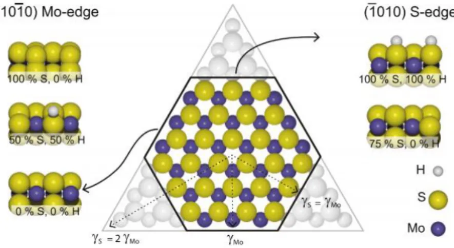
The morphology of the active phase is best described starting from a model consisting of the so-called single-layered MoS2. The hypothetical model serves to illustrate the fact that
hexagonal MoS2 nanoparticles are expected to be terminated by two different types of
low-index edge terminations. From a crystallographic insight, two plans are thermodynamically stable: the (10-10) Mo edge and the (-1010) S edge. These planes is generated by “cutting” Van der Waals interaction ensuring the cohesion of the stacked layers in the bulk structure [1]. The equilibrium shape of the MoS2 nanoparticles is determined by the relative free-edge
energies of these edges. These edge energies have been shown to be sensitive to atom incorporation, sulfidation temperature and H2S / H2 partial pressure ratio, which affect the
slab morphology [16–18]. For instance, the observation of triangular MoS2 nanoparticles with
all three edges terminated by the same type of edge implies that the expressed edge termination is considerably more stable than the other. Hexagonal or truncated triangular nanoparticles, on the other hand, imply that the edge energies are comparable. The dispersion of the two types of edges can be quantified in detail in terms of the two dimensional Wulff construction. In this model, the shape that minimizes the total edge energies is given by the inner envelope of a surface constructed by drawing tangent lines to vectors extending from the same origin with a length proportional to the edge energies[19]. Triangular nanoparticles will result whether the free energy of one edge exceeds the other by a factor of two or more, perfect hexagon is constituted by the same vectors for both edges as shows Figure I.6. Truncated triangular nanoparticles arise for the intermediate situation, e.g. difference between edges is between one and two. Additionally to the proportion of S- and M- edge exposed, both M-edge and S-edge can show different configurations with different sulfur coverage. When the sulfur coverage on M-edge and/or S-edge is less than 100%, sulfur vacancies are created
b) a)
I. Chapter. Introduction
13 on the edges[20–22]. Accordingly, the Mo atoms on M-edge and/or S-edge are coordinatively unsaturated sites (CUS). Thus, the morphology of MoS2 slabs, i.e. the type and quantity of the
edges exposed, is of great importance to the catalytic performance, as well as for Co-promoted MoS2/Al2O3 catalyst because it was further suggested that Co atoms have different
affinities towards M-edge and S-edge [23-24].
Figure I.6. Wulff construction for a hypothetical bulk-truncated MoS2 nanoparticle with the exposed (1
0 ī0) Mo-edge and the (ī0 1 0) S-edge termination. For ƳMo = ƳS the particle will be a perfect
hexagon, while a triangular particle with the Mo edge termination is obtained if ƳS> 2ƳMo[19]
The morphology of MoS2 slabs has been investigated by several methods. One of them
is density functional theory (DFT) calculations that were used by Raybaud et. al [22, 23, 27] to predict MoS2 morphology under different sulfidation conditions. The stability of edge
energy sites under sulfo-reductive condition were investigated by a thermodynamic model combined with DFT calculations. This thermodynamic DFT approach leads to the determination of the local structures of both edges, M- and S-edge, as a function of the chemical potential of sulfur. The chemical potential of sulfur depends on the sulfidation condition, i.e. temperature and partial pressure of H2S and H2. The variation of chemical
potential was detailed studied for different sulfidation conditions. Thus, for typical sulfidation condition (673K and P(H2S)/P(H2) ~ 0.05), the chemical potential calculated is between -1
and -0.8 eV [18]. The edge energies for M- and S-edge with different sulfur coverage (0, 50 and 100%) were also calculated depending on the chemical potential of sulfur; indicating that the energy on M-edge is lower than the energy of S-edge in the wide chemical potential range, which reveals that M-edge is the most stable edge. Thus, triangular-shaped MoS2 terminated
I. Chapter. Introduction
14 pure), while the single-layer nanoparticles can become truncated with both M-edge and S-edge under sulfo-reductive conditions (PH2S/PH2 0.05). Other technique is Scanning
Tunneling Microscopy (STM) that was recently introduced by Lauritsen et al.[23] to study the MoS2 nanoparticles supported on Au substrate prepared by a special procedure under
ultra-high vacuum (UHV) condition. The pure metal Mo was deposited on the Au(111) surface by an e-beam evaporator in the H2S atmosphere of 1x10⁻⁶ mbar at 400K.
Subsequently, the obtained crystal is annealed at 673K for 15 min in the same H2S
atmosphere and single-layered MoS2nanoparticles were formed with the basal (001) plane
parallel to the Au (111) surface. It was imaged that the morphology of MoS2 nanoparticles
can vary from a triangle to a hexagon with sulfo-reductive conditions as shows Figure I.7.
Figure I.7. STM images of single-layered MoS2 nanoparticles synthesised under two different
sulfidation conditions: a) H2S/H2=500 that gives triangular shape and b) H2S/H2=0.07 that forms
hexagonal shape [23]
Finally, Chen et al. using CO adsorption at low temperature followed by FTIR (IR/CO) also detected the change of MoS2 morphology. Recently, the development of IR/CO
method allowed the distinction of Mo located on M- and/or S-edge. Thus, the effect on the morphology of some parameters was studied using this method. The variations of parameters carried out were Mo loading, sulfidation temperature, high pressure, even chelating agent addition. The increase of molybdenum loading and sulfidation temperature, chelating agent addition and high pressure sulfidation modify the morphology from triangular to hexagonal shape [24–27]. Such effect of various parameters could be rationalized considering that a decrease of metal-support interaction leads to change in morphology from triangular to hexagonal shape.
I. Chapter. Introduction
15
1.1.2. Active sites on HDS promoted catalysts
The industrial MoS2-based HDS catalysts contain the so-called “promoters”, which
cause a substantial enhancement of catalytic activity and changes in the selectivity between hydrogenation (HYD) and direct desulfurization (DDS) pathways. The promoters are small amounts of other transition metals (Co or Ni), which are introduced during the impregnation step of the molybdenum salt (co-impregnation) or on the molybdenum oxidic precursor but generally before the sulfidation step. Several models were proposed to account for the formation of CoMoS sites in a conventional catalyst (CoMo /Al2O3) as the contact synergy
model, intercalation model, and decoration model. Delmon proposed the promotion role like a synergic effect between Co9S8 and MoS2 that is called the contact synergy model [28–30].But
this is in contradiction with other studies that propose high addition of promoter (Co/Mo>1) results in a high number of Co9S8 species, which decrease the activity. Instead, Co/Mo ratio
between 0.3-0.4 is well defined to reach the maximum activity in this kind of catalyst [31]. The Co intercalation between MoS2 slabs model was proposed by Voorhoeve and Stuiver
[32,33]. This model was followed by the pseudo-intercalation model proposed by Farragher
and Cossee [34]. They distinguished Co in interaction with the edge and Co in interaction
with the slab bulk, and they observed that energetically the Co in interaction with the bulk was not favorable. Ledoux also proposed another model supported by Co NMR where Co9S8
species are hung to the MoS2 slab by octahedral Co species [35]. In fact, the model considers
a chemical interaction between the Co9S8 particles and the MoS2 slabs by a covalent bond
between the sulfide atoms of the MoS2 particles and the Co included in Co9S8 particles.
Finally, other model and the most generally accepted, was proposed by Topsøe et al [31,36– 41]. In this model (Figure I.8), the Co-Mo-S phase was shown to be MoS2like structures with
the promoter Co atoms located at the edge of MoS2 called CoMoS model or decoration model.
But Co is not only decorating MoS2 particles, some Mossbauer spectroscopy experiments
show three different locations of Co: i) Co in interaction with Al2O3 forming a kind of spinel
CoAl2O4, ii) cobalt sulfide (Co9S8) that is formed for Co addition in excess, and iii) Co in
promotion on MoS2-edge slabs as shows Figure I.8.From this point, the Co-Mo-S model is
similar with the pseudo-intercalation model. It should be noted that the Co-Mo-S structure is not a single bulk phase with a fixed overall CoMoS stoichiometry. Rather, it should be regarded as a family of structures with a wide range of Co concentrations, ranging from pure MoS2 up to full coverage of the MoS2 edges by Co. The Co atoms in Co-Mo-S may not have
I. Chapter. Introduction
16 identical properties due to such effects as different edge-site geometries, Co-Co interactions, and changes in sulfur coordination.
Figure I.8. Schematic view of the different speciespresent in a conventional HDS catalyst CoMo/Al2O3
[39]
It is reported that several factors, such as the sulfidation temperature and pressure or support nature, can influence the structure of CoMoS sites. In particular, the formation of different types of Co-Mo-S structures, namely type I or type II, having different catalytic properties has been proposed. Indeed, in 1984, Candiaet al.[38] proposed that if the chemical bonds between CoMoS structures and the alumina support could be eliminated, the resulting structures would have an increased intrinsic activity. These new structures were termed type II Co-Mo-S. Type-II Co-Mo-S is usually considered as a totally sulfided phase which has a higher activity than type-I (by a factor 2) [10–12]. However, for a long time, there have been limited reports on the difference between type I and type II Co-Mo-S structures. Hinnemannet
al. showed by DFT calculations that in type I structure very specific Mo-O-Al bonds exists
between the Co-Mo-S structures and support. Breaking the Mo-O-Al bonds will transform the type I into the high active type II. The difference in stacking of both Co-Mo-S structures is still controversial until now. Shimada et al. [44] claimed that single-layered MoS2 slabs with
Co at their edges are Co-Mo-S type I, whereas multi-layered MoS2 slabs with Co, except the
bottom layer, are Co-Mo-S type II (Figure I.9). However, Topsøeet al.[45] insisted that the multi-stacking may just be a “by-product” of the weak Metal-Support Interactions and that it is possible to produce single slab Co-Mo-S type II structure.
Figure I.9. Type I and II active sites as proposed by [44]
Al
2O
3CoMoS MoS2
Co9S8
Co
Mono-stacking Multi-stacking Basal bonded MoS2slabs
Catalytically active sites Catalytically inactive sites Catalytically active sites with steric hindrance
I. Chapter. Introduction
17
1.1.2.1 Co promotion: CoMoS morphology
The main effect of Co introduction on the morphology is seen by the fact that Co promoted MoS2 nanoparticles present truncated hexagonal equilibrium morphology, i.e.,
exposing both Mo and S edges. Indeed, DFT calculations similar to the ones exposed previously for MoS2were also performed for Co promoted MoS2slabs. The affinity of Co
promoter for the S-edge and for M-edge can be studied comparing the edge energies with different Co/Mo promotion ratio versus sulfidation conditions. Similar energies for both edges were obtained for high chemical potential of sulfur. On the other hand, the decrease in chemical potential in sulfur by either lowering the partial pressure of H2S or increasing the
sulfidation temperature lead to the enhancement of the affinity of Co for the S-edge at the expense of the one for M-edge site as shows Figure I.10.a[16,21,22,41]. Accordingly, the total promotion of the S-edge is favorable. In addition, Co partial decoration on M-edge (50%) leads to a significant reduction in the calculated edge energy that becomes close to the S-edge value for the same Co content. However, the partial Co decoration on S-edge becomes energetically more favorable than the total Co decoration only for chemical potential of sulfur less than -1.0 eV (conditions out of the HDS range). The calculations were performed also simulating alternated or paired configurations, i.e. Co-Mo-Co-Mo or Co-Co-Mo-Mo bonding, and similar energies were obtained. Then, in typical HDS conditions, the M-edge structure exhibits mixed Co-Mo sites (50% substitution) with 25% of sulfur coverage, the S-atom being preferentially on the top of the Mo atom, and non substituted Mo edge stabilized with 50% of sulfur coverage. The S-edge structure under HDS conditions is 100% Co substituted with 50% of sulfur coverage, Co atoms being in a tetrahedral environment. The various domains of promoter edge content and sulfur coverage are represented in Figure I.10.b with the proportion of each edge. CoMoS nanoparticles close to HDS reaction condition show to be formed by 50% of M-edge, i.e. hexagonal shape
I. Chapter. Introduction
18 Figure I.10. a) Edge energy diagram as a function of ΔµS for Co-promoted M-edge and S-edge and the
most stable sulfur coverages for each edge are reported on the bar charts at the bottom of the diagrams, and b) morphology diagram for the CoMoS nano-crystallites as a function of ΔµS[21]
Additionally, the morphology of Co promoted MoS2 particles were studied by
Scanning Tunneling Microscopy. The STM experiment was carried out on molybdenum deposited on an Au (111) sheet under H2S atmosphere, leading to small Mo particles. These
were then capped in a mixture of Co and Mo by co-deposition of the two metals to ensure efficient mixing of the metal. These particles were then annealed in a H2S atmosphere to 723
K to facilitate crystallization. STM images showed truncated triangular shape for these nanoparticles. Co presence was only revealed at S edge by the detection of protrusion at this edge [19].
Figure I.11. STM image of Co-Mo-S nanoparticles [46] a)
I. Chapter. Introduction
19 Compared to un-promoted MoS2 nanoparticles, where the S-edge is fully saturated
with 100% S even under HDS conditions, Co promoted S edge has a reduced 50% S coverage. The reduced S coverage is a result of the preferred valence state of Co (II) compared to Mo (IV). Co promoted S-edge can therefore be thought as an active edge with already formed vacancies (CUS) with the ability to bond S containing compounds during HDS reactions, i.e. without the first requirement of vacancies formation as in the case of non promoted edge. Dealing with the selectivity, Moses et al. conclude that both CoMoS S-edge and unpromoted M-edge may participate in hydrogenation, whereas the CoMoS S-edge is primarily responsible for the promotion of the DDS pathway [47,48].
1.1.3. Support effect in HDS catalysts
The properties that characterize a good support can be classified in:
i) Great textural properties such as high surface area and developed porosity relative to stable mesoporous.
ii) High thermal stability,
iii) Intermediate support-metal interaction that lead to good metal dispersion. iv) Low cost and scalability.
Several metal oxides such as Al2O3, SiO2, TiO2, ZrO2, etc, were used as support for HDS
catalysts [7,49–60]. The most used support in hydrodesulfurization catalysts is alumina, because of its great textural properties, good metal dispersion, and low cost.
The different surface properties that are characteristic of each support surface influence the metal-support interaction in the oxidic and sulfided forms and hence, the resulting metal dispersion, slab stacking, slab length and MoS2 morphology which lead to different catalytic
activity [52]. Thus, the differences in activity obtained on different support are explained in a general view by the different support-metal interaction [24,61–63]. One general way to characterize such interaction is to consider it as strong or weak according to the support. A weak interaction was reported for carbon or silica supports [19], while strong interaction was detected for MgO or TiO2 [64,65]. This interaction can be reduced by chelating agent addition
as citric acid (CA) or nitrilotriacetic acid (NTA), and increased by the addition of some additives as phosphorous. However, the interaction can be discussed according to several precise points of view: the anchorage point on the support (OH, Lewis acid sites), the
I. Chapter. Introduction
20 anchorage mode (edge or parallel anchorage), the nature of the anchorage (physical anchorage or chemical anchorage), the morphology of the anchored slab (with existence or not of epitaxy phenomena)… Such effects can be generalized in term of geometric effects. Also, the effect of the support can be considered as electronic… [66,67]. In this work, we have selected the usual support (Al2O3), a weak (SiO2) and strong (TiO2) interacting support. The main
differences between these supports are described more precisely thereafter.
1.1.3.1. Anchorage nature on support surface
The isoelectric point (IEP) characteristic of each support and the pH of the impregnation solution of Mo play an important role in molybdenum oxide species formation and in the absorption of Molybdate anions. The impregnation solution is required to have a pH lower to the support IEP to obtain an optimum species absorption. The isoelectric point characteristic of Al2O3, TiO2, and SiO2 are 8, 6, and 2 respectively [68]. Hence, catalysts prepared using
different supports but with same impregnation condition and the same metal loading cannot have the same dispersion.
1.1.3.1.1. Aluminum oxide (ϒ-Al2O3)
Gamma alumina is the most used support in HDS catalyst. There are several interesting factors that makes the alumina the support of choice: high surface area (100-400 m2/g), porous with meso- size, thermal stability, high capacity to catalyst regeneration and good metal dispersion. The alumina surface is composed by acid Lewis sites, Al3+, and hydroxyl group which can have basic, neutral or acid character as represented in Figure I.12. Since alumina is the most used catalyst support in many applications, the well understanding of the surface is required. For that, many studies have been performed to know the characteristic of it surface and its interaction with the metal precursors. Thus, many studies show the alumina-molybdate interaction is first with basic hydroxyl group from alumina surface [2,66,69]. However, some interactions with neutral or acid hydroxyl group and Lewis acid sites (Al3+) are also detected for higher metal loading. Moreover, gamma alumina surface were study by DFT calculations to predict the more stable planes, and study some influences in its chemistry properties to later study the interaction between MoS2
nanoparticles and the alumina surface. For that, four different plans were studied and two were obtained energetically stable under HDS condition, (110) and (100) surface. Ƴ-alumina (100) surface was not hydroxylated under HDS conditions. Moreover, the Ƴ-alumina (110) surface was hydroxylated with 8.8 OH/nm2 and both not sulfided [70].
I. Chapter. Introduction
21 Figure I.12. Scheme of adsorption sites and molybdate adsorption mode [66,69]
1.1.3.1.2. Silicon oxide (SiO2- silica gel)
Silica is an inert material that presents high thermal stability (higher than 1000°C) and high surface area (300-1000 m2/g). These qualities make interesting the use of silica as support for HDS catalysts. Silica surface is formed by acid hydroxyl group as is represented in Figure I.13. Silica surface is really sensitive to heating treatment, since it is formed by OH groups and it can be dehydrated to form siloxane. On the other hand, the surface can be hydrated forming germinal silanol and vicinal silanol interacting through H bonding [71]. The presence of only hydroxyl groups on the surface leads to weak interaction with the metal and then to a poor metal dispersion as revealed by the formation of MoO3 species after calcination
treatment [72].
Figure I.13. Scheme of silica surface [71]
1.1.3.1.3. Titanium oxide (anatase- and rutile-TiO2 phases)
Titanium dioxide crystallizes in three different structures: brokite (rhombohedrical, a=5.436 Å, b=9.166 Å, c=5.135 Å), rutile (tetragonal, a=b=4.584 Å, c=2.953 Å) and anatase (tetragonal, a=b=3.782 Å, c=9.502 Å). But, of these three only rutile and anatase structures are
I. Chapter. Introduction
22 used in catalysis application, and they are the ones used in this work as support of HDS catalysts. Anatase is a metastable structure; hence it has a low thermal stability (maximum temperature, around 400ºC). At high temperatures (600ºC), anatase becomes rutile which is a stable structure.
Anatase and rutile unit cells are shown in Figure I.14.a. In both structures, the basic building block consists of a titanium atom surrounded by six oxygen atoms in a more or less distorted octahedral configuration. In each structure, the two bonds between the titanium and the oxygen atoms at the apices of the octahedron are slightly longer. In both structure, the stacking of the octahedra results in threefold coordinated oxygen atoms [73]. Ramamoorthy et
al. calculated the total energy of periodic rutile TiO2 slabs using a self-consistent ab initio
method where the (110) surface has the lowest surface energy (0.31 J/m2), and (001) the highest [74]. However, (101) face is the thermodynamically most stable surface in anatase TiO2 (0.44 J/m2) [75].
The principal reason that makes TiO2 an interesting material in catalysis is its surface. It
is full of defects and it can be categorized in step edges, oxygen vacancies, line defects, common impurities, and the manifestation of crystallographic shear planes (CSPs) at surfaces [73]. The bulk structure of reduced TiO2-x crystals is quite complex with a various types of
defects such as doubly charged oxygen vacancies, Ti3+ and Ti4+ interstitials, and planar defects such as CSPs. The defect structure varies with oxygen deficiency which depends on temperature, gas pressure, impurities, etc.
Generally, the most used titania powders are formed by pure anatase or by the mixture of rutile and anatase as the commercial titania denoted Degussa P25 which is composed by 80-90% of anatase and the complement of rutile. Since, Titania is mostly formed by anatase phase, it is interesting to study the anatase-TiO2 surface. Thus, Costa et al. performed the
study about the more stable planes in order to predict the interaction between anatase-TiO2
surface and MoS2 nanoparticles by DFT calculations. For that, the two principal
crystallographic surfaces of anatase-TiO2 were considered. Under HDS conditions, the (101)
surface of anatase was considered dehydrated and not sulfided. The (001) anatase was found hydroxylated and partially sulfided, with a hydroxyl coverage of 3.5 OH/nm2 and S coverage of 1.7 S/nm2. The OH groups are Ti5c (fivecoordinated) and OH monocoordinated (µ1-OH)
I. Chapter. Introduction
23 Figure I.14. a) Unit cells for anatase and rutile structure [73] and b) Wulff construction for both
structures
Thus, finally, MoOx species or MoS2 nanoparticles can be differently anchorage in the
support surface and it strongly depends on the surface nature. Gamma-Al2O3 surfaceshows
different anchorage point as hydroxyl group with different acidity and Lewis acid sites, Al3+. Similar anchorage can be predicted by TiO2 surface due to it is formed by hydroxyl groups
and Lewis acid sites, Ti4+ although this material shows a specific behavior due to the high defects numbers. And controversially SiO2 surface shows the main anchorage with hydroxyl
group.
1.1.3.2. Anchorage mode
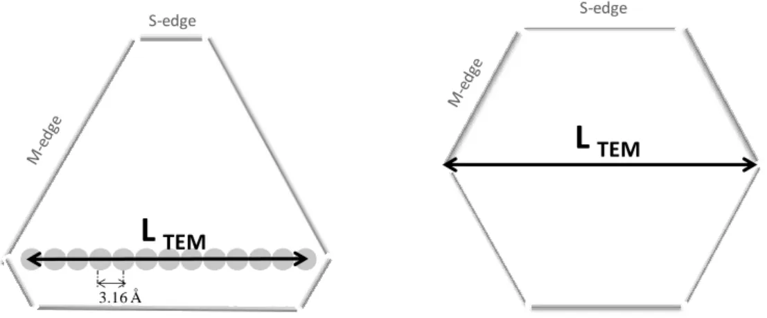
One important aspect of the metal-support interaction is the way the slab is anchored to the surface i.e. through basal plane interaction (parallel anchorage) or through the edges (edge anchorage). Indeed, from TEM image observations, while MoS2 was uniformly dispersed
mainly through parallel anchorage on the surface of SiO2 and Al2O3. Specific slab
edge-anchoring were found for TiO2 catalysts [44,76,77]. Thus, several studies were carried out by
DFT calculation on the MoS2-support interaction considering two supports Al2O3 and TiO2
[78–80]. First, the interaction of Mo6Sn clusters represented with M-edge termination
(triangular shape) with the support was investigated [80]. Various possible types of interactions were considered which are susceptible to be formed when the particles are anchored through the edge or the corner via H bonds and van der Walls interactions, both of which may be responsible for the parallel orientation of single MoS2 slab. In addition, an
epitaxial relationship of the M-edge of MoS2 with anatase (110) or (001) surface was found.
When size effects are taken into account, particles up to 90 Å in diameter may be anchored
Anatase Rutile [010] [001] [100] [001] [010] Anatase Rutile a) b) (001) (101) (01
ī
) (10ī
) (001) (101)(011) (110) (ī
10) (1 0 0 )I. Chapter. Introduction
24 through the M-edge on the anatase surface. Such a strong interaction is not evidenced for alumina. Only particles with M-edge length less to 15 Å are found to interact strongly with the support and particles of larger size parallel to the surface. For this epitaxial relationship, two factors may explain the increased catalytic activity of MoS2/anatase versus MoS2/alumina: the
stabilization of small anchored particles and the existence of a stable S-vacancy at the edge of those anchored particles. DFT calculations predicted that M-edge was energetically more stable than S-edge termination over a wide range of chemical potentials, and for this reason firstly the Medge termination was studied. But the study about the Sedge interaction with -OH group by Hinnemann et al. [37] leads to the study of the interaction of S-edge termination with alumina and titania supports [78]. Wetting effect was also studied for the alumina and titania supports. The edge wetting of MoS2 particles showed an important effect for
anatase-TiO2; instead, this effect was not so strong for alumina catalyst. Then, for Mo/Al2O3 catalyst,
MoS2 nanoparticles exhibit chemical interaction as Mo-O-Al bonds for M- and S-edges in
small particles sizes (< 15 Å). Besides the particles showed parallel orientations stabilized by H bonds and van der Waals interactions for normal particles size, i.e. higher than 15 Å. On the other hand, Mo/TiO2 catalyst showed an epitaxial relationship between M-edge of MoS2
nanoparticles and the support surface at (101) and (001) plans with the formation of Mo-O-Ti-S-Mo rings. This epitaxy is not possible between the S-edge and titania surface. The wetting effect in anatase-TiO2 leads to the formation of trapezoidal MoS2 morphology, with two
predominant M-edge and one single S-edge.
1.1.3.3. Support effect on the MoS2 morphology
The MoS2 morphology supported in different supports were studied by Scanning
Tunneling Microscopy (STM). Lauritsen et al. was the pioneer to obtain an image from MoS2
nanoparticles supported on Au (111) [81]. This study was continued using carbon or (110) rutile-TiO2 as support using the same technique [82]. Triangular or truncated-triangular shape
was obtained for MoS2 supported on Au (111) depending on the sulfidation condition, thus
hexagonal shape was detected for MoS2 supported on graphite, and elongated hexagonal
I. Chapter. Introduction
25 Figure I.15. STM images for MoS2 slabs supported on Au (111), graphite and rutile-TiO2 (110)
1.1.3.4. Support effect on the activity
The study of the support effect on the catalytic activity revealed equally that Mo/TiO2
catalyst shows four times higher intrinsic activity than Mo/Al2O3 catalyst [53,58,83–86]. As
well, Mo/SiO2 catalyst shows also higher intrinsic activity than Al2O3. These changes in
activity can be explained by the total sites available, metal-support interaction, specific MoS2
orientation and high stacking degree. The high intrinsic activity recorded for Mo/TiO2 catalyst
can be explained by the edge-bonding interaction between the MoS2 and the support [44], that
lead to the specific epitaxial configuration detected by DFT calculations. Moreover, some authors also explained the high activity by a electronic effect, or indirect promotion by Ti [83,85,87]. Moreover, the high intrinsic activity detected for Mo/SiO2 catalyst is explained
due to the high slab stacking number forming the so-called type II active sites consequence of the weak metal-support interaction. However, the synergy between Ni(Co) and Mo in the catalysts prepared by conventional co-impregnation technique appears to be lower for TiO2
than Al2O3 catalysts, and afterwards less active. Controversially, CoMo supported on silica
showed be more active than CoMo supported on alumina catalyst due to the formation of CoMoS phase with high stacking number that are called CoMoS type II [88]. Instead, CoMo supported on Al2O3 and TiO2 lead to the formation of CoMoS type I.
In conclusion, it is expected that a weak metal-support interaction leads to form hexagonal MoS2 shape and highly stacked slabs on carbon and silica supports. In contrast,
strong metal-support interaction should lead to form triangular MoS2 shape and monolayer
slabs [89]. Titania catalysts have a specific behavior due to the metal-support interaction Au (111) support Graphite support Rutile-TiO2(110) support
I. Chapter. Introduction
26 explained by the wetting effect or the so called strong ligand effect that lead them to have high intrinsic activity.
1.2 . Hydrodesulfurization model reactions
The hydrodesulfurization (HDS) reaction consists in removing sulfur from sulfur-containing molecules. This reaction is carried out using hydrogen in excess and high temperature between 623 and 673 K. The fundamental transformations in HDS are the same for all mechanisms: i) adsorption of the sulfur compound to the active site, ii) hydrogenation of unsaturated C=C bonds, iii) cleavage of two carbon-sulfur bonds, iv) addition of hydrogen to the broken bonds of both sulfur and carbon, v) release of the hydrocarbon product from the catalytic site, vi) release of the H2S from the site. The sequence of these transformations can
be varied, and depends on the sulfur-containing molecule. Fuel feeds can be formed by different sulfur-containing molecules from thiols (R-S-R), which are characterized by its small molecule size, to polycyclic aromatic compounds such as methyldibenzothiophenes that present big molecule size. The high steric hindrance presented by large molecules makes more difficult to carry out the HDS reaction as shows Figure I.16 in particular in the case of methyl substituted compounds. For that reason, catalyst enhancement is necessary since mostly these compounds form actual fuel feedstock.
Figure I.16. Sulfur compounds feed and different reaction rate[52]
Generally, the HDS reaction takes place by the following two mechanisms: direct desulfurization pathway (DDS), in which the C-S bond is broken without preliminary hydrogenation step; and hydrogenation pathway (HYD)[90–92]. These two mechanisms occur in different ways depending on the sulfur-containing molecules, even each pathway can be performed in different active sites as the literature predicts.
I. Chapter. Introduction
27 Since sulfur elimination is more difficult for aromatic compounds than for linear sulfur compounds, in the present work, two different aromatics sulfur compounds were chosen as model molecules, to study the catalytic activity for HDS reaction: thiophene and dibenzothiophene. The HDS reaction scheme for thiophene and dibenzothiophene are shown below.
1.2.1 Mechanism of hydrodesulfurization of Thiophene
Thiophene is a sulfur-containing molecule with medium size. This molecule is the conventional one to study HDS reaction since it is an aromatic compound without high steric hindrance.
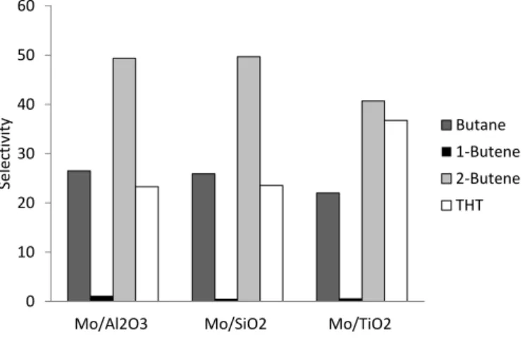
Thiophene molecule undergoes first a pre-hydrogenation of one of the double bond. Therefore, thiophene becomes dihydrothiophene that normally is just a transition product. Then, two different pathways can be carried out, hydrogenation (HYD) or direct desulfurization (DDS). DDS pathway form 1,3-Butadiene, which is a transition product is not detected because it is not a stable product. It is hydrogenated forming 1-Butene or 2-Butene, products that can be formed by both pathways direct desulfurization and hydrogenation. Moreover, HYD pathway leads to the formation of Tetrahydrothiophene, which is detected as reaction product. Then, the hydrogenation can continue forming 1-Butene or 2-Butene. The limitation of thiophene as model molecule is clearly shown, both pathways, HYD and DDS, lead to the formation of 1-Butene and 2-Butene as reaction products. Thus, Tetrahydrothiophene (THT) can be considered as hydrogenation product, and 1-Butene, 2-Butene and Butane as products of the mixture of hydrogenation and direct desulfurization pathway.
Moses et.al studied the thiophene reaction mechanism by DFT calculations for MoS2
nanoparticles. The reaction selectivity was studied taking into account both M- and S-edge active sites. The product energies in reaction with M- or S-edge sites were calculated and the implication of different active sites in the different pathway was detected, i.e. C-S scission was predicted to be carried out in S-edge, while hydrogenation pathway was going on M-edge sites[93]. Additionally, the same calculations were performed for CoMoS sites, considering that Co decorates only S-edge sites. Thus, Cobalt located on S-edge showed to be the responsible of C-S scission while M-edge non-promoted was the responsible of hydrogenation pathway[94].
I. Chapter. Introduction
28 Figure I.17. Scheme of Thiophene reaction and pathway [95]
1.2.2 Mechanism of hydrodesulfurization of Dibenzothiophene
The kind of HDS model molecule has an influence in the active site behaviors, i.e. the active sites do not react in the same line for all sulfur compounds. The molecule with high steric hindrance cannot be adsorbed at single edge sulfur vacancies; likewise the hydrogenation (HYD) pathway may become the dominant route since it is less sensitive to steric effects. Thus, the HYD activity is becoming increasingly more important for heavy crude oils. For that reason, a molecule with high steric hindrance as dibenzothiophene (DBT) is considered to study the catalytic activity for some catalysts in the present work.
The Dibenzothiophene mechanism for HDS reaction is shown in Figure I.18. Two different pathways are characteristic of this reaction: Direct desulfurization (DDS) and Hydrogenation (HYD). Unlike Thiophene molecule, products from DDS or HYD can be detected after reaction, allowing a selectivity study for the active sites in HDS reaction. Biphenyl is the stable product obtained after DDS reaction pathway, while cyclohexylbenzene is the product obtained of hydrogenation pathway. It is normally considered that DDS reactions take place by sulfur removal on the so-called sulfur vacancies formed on the edges of the MoS2 nanoparticles in interplay with edge sulfydryl groups (S–H). For the HYD
pathway, on the other hand, the situation is under much more in debate [96]. Several studies have proposed a two-site model, where one or more hydrogenation steps occur on a certain type of site where adsorption is less sterically hindered prior to sulfur removal on a regular edge sulfur vacancy[97,98].In particular, it was proposed that the so-called brim sites in close
H2 623K Catalyst Thiophene Dihydrothiophene Tetrahydrothiophene THT DHT 1,3-Butadiene Trans-2-Butene Cis-2-Butene 1-Butene Butane H2S H2S H2
I. Chapter. Introduction
29 vicinity to edge S-H groups presents a favorable geometry as active sites for the hydrogenation step during the HYD pathway [12,13].
Figure I.18. Pathways of hydrodesulfurization reaction for Dibenzothiophene (DBT)
1.3 . Scope of the thesis
The investigation of the active phase-support interaction is of paramount importance to make new progress in understanding the effect of the support in active phase formation and therefore its action in the HDS catalytic reaction. The support can have effects in the active phase dispersion and morphology as well as electronic effects. Recently, IR/CO method was used to distinguish Mo located on M- and S-edge for Mo/Al2O3 catalysts; and thus to predict
the MoS2 slab morphology on alumina support [25,26,99,100]. Several factors were studied as
temperature and high-pressure sulfidation, variation in Mo loading and the addition of citric acid in the preparation step. All those factors have an effect in metal-support interaction producing a change in the MoS2 morphology. Some influences of the support effect in the
catalytic activity are already reported in the literature but without any unambiguous explanation. Hence, the goal of this work is to study mono- (Mo) and bimetallic (CoMo) catalysts supported on three different metal oxides known to have different chemistry properties: alumina, silica and titania. Therefore, MoS2 and CoMoS nanoparticles will present
different anchoring with the support surface producing changes in the catalytic activity and in the actives sites nature. These different active sites have been studied by IR/CO method, which allows determining the MoS2 slab morphology as well as the concentration of Mo edge
Dibenzothiophene HYD DDS H2S H H2S 2 H2 Biphenyl Cyclohexylbezene 1,2,3,4,10,11-Hexahydro Dibenzothiophene
I. Chapter. Introduction
30 sites available for HDS reaction. And thus, it leads to understand the role of the active sites in the HDS reaction. The distinction of Mo located on M-edge and S-edge by IR/CO for non-promoted catalysts leads to the possibility of the study of the Co decoration affinity to M- or S-edge sites. Therefore, in the case of promoted catalysts, a new development of IR/CO method has been carried out to get information about the Co promoted sites, i.e. degree and nature. Thus, in this work, the method for these promoted catalysts will be implemented thanks to a chemiometry method in order to refine the attribution of IR bands.
1.4 . References
[1] H. Toulhoat, P. Raybaud, Catalysis by Transition Metal Sulphides: From Molecular Theory to Industrial Application, Editions Technip, 2013.
[2] I.E. Wachs, Catal. Today 27 (1996) 437–455.
[3] E. Payen, R. Hubaut, S. Kasztelan, O. Poulet, J. Grimblot, J. Catal. 147 (1994) 123–132. [4] J. QUARTARARO, S. MIGNARD, S. KASZTELAN, J. Catal. 192 (2000) 307–315. [5] L.S. Byskov, J.K. Norskov, B.S. Clausen, H. Topsoe, J. Catal. 187 (1999) 109–122.
[6] H. Topsoe, R. Candia, N.Y. Topsoe, B.S. Clausen, Bull. Des Soc. Chim. Belges 93 (1984) 783–806.
[7] C. Dujardin, M.A. Lelias, J. van Gestel, A. Travert, J.C. Duchet, F. Mauge, Appl. Catal. A Gen. 322 (2007) 46–57.
[8] Y. OKAMOTO, J. Catal. 70 (1981) 445–448.
[9] S.J. Tauster, T.A. Pecoraro, R.R. Chianelli, J. Catal. 63 (1980) 515–519.
[10] S. Kasztelan, H. Toulhoat, J. Grimblot, J.P. Bonnelle, Appl. Catal. 13 (1984) 127–159.
[11] E.J.M. Hensen, P.J. Kooyman, Y. van der Meer, A.M. van der Kraan, V.H.J. de Beer, J.A.R. van Veen, R.A. van Santen, J. Catal. 199 (2001) 224–235.
[12] J. V Lauritsen, M. Nyberg, R.T. Vang, M. V Bollinger, B.S. Clausen, H. Topsoe, K.W. Jacobsen, E. Laegsgaard, J.K. Norskov, F. Besenbacher, Nanotechnology 14 (2003) 385–389. [13] J. V Lauritsen, M. Nyberg, J.K. Norskov, B.S. Clausen, H. Topsoe, E. Laegsgaard, F.
I. Chapter. Introduction
31 [14] M. V Bollinger, J. V Lauritsen, K.W. Jacobsen, J.K. Norskov, S. Helveg, F. Besenbacher,
Phys. Rev. Lett. 87 (2001).
[15] S. Kasztelan, H. Toulhoat, J. Grimblot, J.P. Bonnelle, Bull. Soc. Chim. Belg. 93 (1984) 807– 811.
[16] H. Schweiger, P. Raybaud, H. Toulhoat, J. Catal. 212 (2002) 33–38.
[17] H. Schweiger, P. Raybaud, G. Kresse, H. Toulhoat, J. Catal. 207 (2002) 76–87.
[18] P. Raybaud, J. Hafner, G. Kresse, S. Kasztelan, H. Toulhoat, J. Catal. 189 (2000) 129–146. [19] A.S. Walton, J. V Lauritsen, H. Topsoe, F. Besenbacher, J. Catal. 308 (2013) 306–318. [20] P. Raybaud, J. Hafner, G. Kresse, H. Toulhoat, Surf. Sci. 407 (1998) 237–250.
[21] E. Krebs, B. Silvi, P. Raybaud, Catal. Today 130 (2008) 160–169.
[22] L.S. Byskov, J.K. Norskov, B.S. Clausen, H. Topsoe, Catal. Letters 64 (2000) 95–99.
[23] J. V Lauritsen, M. V Bollinger, E. Laegsgaard, K.W. Jacobsen, J.K. Norskov, B.S. Clausen, H. Topsoe, F. Besenbacher, J. Catal. 221 (2004) 510–522.
[24] J. Chen, F. Maugé, J. El Fallah, L. Oliviero, J. Catal. 320 (2014) 170–179.
[25] J. Chen, E. Dominguez Garcia, E. Oliviero, L. Oliviero, F. Maugé, J. Catal. 339 (2016) 153– 162.
[26] J. Chen, V. Labruyere, F. Mauge, A.-A. Quoineaud, A. Hugon, L. Oliviero, J. Phys. Chem. C 118 (2014) 30039–30044.
[27] J. Chen, L. Oliviero, X. Portier, F. Maugé, (2015).
[28] G. Hagenbach, P. Courty, B. Delmon, J. Catal. 31 (1973) 264–273. [29] S. Eijsbouts, Appl. Catal. A Gen. 158 (1997) 53–92.
[30] B. Delmon, G.F. Froment, (1996) 37–41.
[31] C. Wivel, R. Candia, B.S. Clausen, S. Morup, H. Topsoe, J. Catal. 68 (1981) 453–463. [32] R.J.H. Voorhoeve, J.C.M. Stuiver, J. Catal. 23 (1971) 243–252.
[33] R.J.H. Voorhoeve, J. Catal. 23 (1971) 236–242.
I. Chapter. Introduction
32 [35] M. LEDOUX, J. Catal. 96 (1985) 189–201.
[36] R. Candia, H. Topsoe, B.S. Clausen, Actas Simp. Iberoam. Catal., 9th 1 (1984) 211–221. [37] B. Hinnemann, J.K. Norskov, H. Topsoe, J. Phys. Chem. B 109 (2005) 2245–2253.
[38] R. Candia, O. Soerensen, J. Villadsen, N.Y. Topsoe, B.S. Clausen, H. Topsoe, Bull. Des Soc. Chim. Belges 93 (1984) 763–773.
[39] H. Topsoe, B.S. Clausen, Catal. Rev. Eng. 26 (1984) 395–420.
[40] H. Topsoe, B.S. Clausen, F.E. Massoth, Hydrotreating Catalysis, Springer, Berlin-Heidelberg, 1996.
[41] L.S. Byskov, B. Hammer, J.K. Norskov, B.S. Clausen, H. Topsoe, Catal. Letters 47 (1997) 177–182.
[42] H. Topsoe, B.S. Clausen, N.Y. Topsoee, E. Pedersen, Ind. Eng. Chem. Fundam. 25 (1986) 25– 36.
[43] Http://www.eia.doe.gov/oiaf/servicerpt/ulsd/figd3.html, (n.d.). [44] H. Shimada, Catal. Today 86 (2003) 17–29.
[45] H. Topsoe, Appl. Catal. a-General 322 (2007) 3–8.
[46] F. Besenbacher, M. Brorson, B.S. Clausen, S. Helveg, B. Hinnemann, J. Kibsgaard, J. Lauritsen, P.G. Moses, J.K. Norskov, H. Topsoe, Catal. Today 130 (2008) 86–96.
[47] P.G. Moses, B. Hinnemann, H. Topsoe, J.K. Norskov, J. Catal. 268 (2009) 201–208. [48] P.G. Moses, B. Hinnemann, H. Topsoe, J.K. Norskov, J. Catal. 248 (2007) 188–203. [49] G. Perot, Catal. Today 86 (2003) 111–128.
[50] C.E. Hedoire, C. Louis, A. Davidson, M. Breysse, F. Mauge, M. Vrinat, J. Catal. 220 (2003) 433–441.
[51] T.D. Tang, L. Zhang, W.Q. Fu, Y.L. Ma, J. Xu, J. Jiang, G.Y. Fang, F.S. Xiao, J. Am. Chem. Soc. 135 (2013) 11437–11440.
[52] T.K.T. Ninh, L. Massin, D. Laurenti, M. Vrinat, Appl. Catal., A 407 (2011) 29–39. [53] T.K.T. Ninh, D. Laurenti, E. Leclerc, M. Vrinat, Appl. Catal. A Gen. 487 (2014) 210–218.
I. Chapter. Introduction
33 [54] S.M.A.M. Bouwens, F.B.M. van Zon, M.P. van Dijk, A.M. van der Kraan, V.H.J. de Beer,
J.A.R. van Veen, D.C. Koningsberger, J. Catal. 146 (1994) 375–393.
[55] C. Glasson, C. Geantet, M. Lacroix, F. Labruyere, P. Dufresne, J. Catal. 212 (2002) 76–85. [56] P. Afanasiev, Catal. Commun. 9 (2008) 734–739.
[57] R.G. Leliveld, A.J. Van Dillen, J.W. Geus, D.C. Koningsberger, J. Catal. 171 (1997) 115–129. [58] P. Castillo-Villalón, J. Ramírez, R. Cuevas, P. Vázquez, R. Castañeda, Catal. Today 259 (2016)
140–149.
[59] J. Ramirez, F. Sanchez-Minero, Catal. Today 130 (2008) 267–271. [60] R. Cattaneo, T. Shido, R. Prins, J. Catal. 185 (1999) 199–212.
[61] M.A. Lélias, J. van Gestel, F. Maugé, J.A.R. van Veen, Catal. Today 130 (2008) 109–116. [62] M.A. Lelias, E. Le Guludec, L. Mariey, J. van Gestel, A. Travert, L. Oliviero, F. Mauge, Catal.
Today 150 (2010) 179–185.
[63] C. Kwak, M.Y. Kim, K. Choi, S.H. Moon, Appl. Catal. A Gen. 185 (1999) 19–27.
[64] F. Cesano, S. Bertarione, A. Piovano, G. Agostini, M.M. Rahman, E. Groppo, F. Bonino, D. Scarano, C. Lamberti, S. Bordiga, L. Montanari, L. Bonoldi, R. Millini, A. Zecchina, Catal. Sci. Technol. 1 (2011) 123–136.
[65] J. Ramirez, G. Macias, L. Cedeno, A. Gutierrez-Alejandre, R. Cuevas, P. Castillo, Catal. Today 98 (2004) 19–30.
[66] P. Blanchard, C. Lamonier, A. Griboval, E. Payen, Appl. Catal., A 322 (2007) 33–45.
[67] M.J. Vissenberg, L.J.M. Joosten, M.M.E.H. Heffels, A.J. van Welsenes, V.H.J. de Beer, R.A. van Santen, J.A.R. van Veen, J. Phys. Chem. B 104 (2000) 8456–8461.
[68] D.S. Kim, K. Segawa, T. Soeya, I.E. Wachs, J. Catal. 136 (1992) 539–553.
[69] J.A.R. VAN VEEN, H. DE WIT, C.A. EMEIS, P.A.J.M. HENDRIKS, 582 (1987) 579–582. [70] P.R. H. Toulhoat, Catalysis by Transition Metal Sulphides, Paris, France, 2013.
[71] L.T. Zhuravlev, Colloids Surfaces A Physicochem. Eng. Asp. 173 (2000) 1–38. [72] Y. Okamoto, Appl. Catal. A Gen. 226 (2002) 115–127.