HAL Id: hal-02560219
https://hal.archives-ouvertes.fr/hal-02560219
Submitted on 18 Dec 2020HAL is a multi-disciplinary open access archive for the deposit and dissemination of sci-entific research documents, whether they are pub-lished or not. The documents may come from teaching and research institutions in France or abroad, or from public or private research centers.
L’archive ouverte pluridisciplinaire HAL, est destinée au dépôt et à la diffusion de documents scientifiques de niveau recherche, publiés ou non, émanant des établissements d’enseignement et de recherche français ou étrangers, des laboratoires publics ou privés.
Imprinting isolated single iron atoms onto mesoporous
silica by templating with metallosurfactants
Y. Berro, S. Gueddida, Y. Bouizi, C. Bellouard, El-E. Bendeif, A. Gansmuller,
A. Celzard, V. Fierro, D. Ihiawakrim, O. Ersen, et al.
To cite this version:
Y. Berro, S. Gueddida, Y. Bouizi, C. Bellouard, El-E. Bendeif, et al.. Imprinting isolated single iron atoms onto mesoporous silica by templating with metallosurfactants. Journal of Colloid and Interface Science, Elsevier, 2020, 573, pp.193-203. �10.1016/j.jcis.2020.03.095�. �hal-02560219�
Imprinting isolated single iron atoms onto mesoporous silica by templating
1with metallosurfactants
2 3 4Y. Berro,1,2,3 S. Gueddida,2 Y. Bouizi,1 C. Bellouard,4,* El-E. Bendeif,5 A. Gansmuller,5 A.
5
Celzard,6 V. Fierro,6 D. Ihiawakrim,7 O. Ersen,7 M. Kassir,3 F. El Haj Hassan,3 S. Lebegue,2
6
M. Badawi,2 N. Canilho,1 and A. Pasc1,*
7 8
1
L2CM UMR CNRS 7053, Université de Lorraine, 54506 Vandœuvre-lès-Nancy, France
9
2
LPCT UMR CNRS 7019, Université de Lorraine, 54506, Vandœuvre-lès-Nancy, France
10
3
PRASE, Université Libanaise, Hadath, Lebanon
11
4
IJL UMR CNRS 7198, Université de Lorraine, 54000 Nancy, France
12
5
CRM2 UMR CNRS 7036, Université de Lorraine, 54506 Vandœuvre-lès-Nancy, France
13
6
IJL UMR CNRS 7198, Université de Lorraine, 88000 Epinal, France
14
7
IPCMS UMR CNRS 7504, Université de Strasbourg, 67034 Strasbourg, France
15 16
Corresponding author: christine.bellouard@univ-lorraine.fr,
andreea.pasc@univ-17 lorraine.fr 18 19 Abstract 20 Hypothesis 21
One of the main drawbacks of metal-supported materials, traditionally prepared by the
22
impregnation of metal salts onto pre-synthesized porous supports, is the formation of large
23
and unevenly dispersed particles. Generally, the larger are the particles, the lower is the
24
number of catalytic sites. Maximum atom exposure can be reached within single-atom
25
materials, which appear therefore as the next generation of porous catalysts.
26
Experiments
27
Herein, we designed single iron atom-supported silica materials through sol-gel hydrothermal
28
treatment using mixtures of a non-ionic surfactant (Pluronic P123) and a metallosurfactant
29
(cetyltrimethylammoniumtrichloromonobromoferrate, CTAF) as porogens. The ratio between
30
the Pluronic P123 and the CTAF enables to control the silica structural and textural
31
properties. More importantly, CTAF acts as an iron source, which amount could be simply
32
tuned by varying the non-ionic/metallo surfactants molar ratio.
34
Findings
35
The fine distribution of iron atoms onto the silica mesopores results from the iron distribution
36
within the mixed micelles, which serve as templates for the polymerization of the silica
37
matrix. Several characterization methods were used to determine the structural and textural
38
properties of the silica material (XRD, N2 sorption isotherms and TEM) and the homogeneous
39
distribution and lack of clustering of iron atoms in the resulting materials (elemental analysis,
40
magnetic measurements, pair distribution function (PDF), MAS-NMR and TEM mapping).
41
The oxidation and spin state of single-iron atoms determined from their magnetic properties
42
were confirmed by DFT calculations. This strategy might find straightforward applications in
43
preparing versatile single atom catalysts, with improved efficiency compared to nanosized
44 ones. 45 Graphical abstract 46 47 Keywords: 48
Single iron atom catalysts, mesoporous silica, metallosurfactants, Density Functional Theory,
49
spin state, pair distribution function.
50
1. Introduction
51
Increasing the number of active sites of a material in order to enhance its catalytic
52
activity is a continuous challenge [1–3]. This is commonly addressed by increasing the
53
active surface area of catalytic particles and thus by decreasing their size. The most
54
promising catalysts with the lowest size limit and thus, the highest atom efficiency are
55
considered isolated single atom catalysts (SACs) [4–10]. Several studies already
56
demonstrated the efficiency of SACs compared to nanosized catalysts. For instance, in
57
the water gas shift reaction [11] catalyzed by Ir1/FeOx, single atoms promoted more
than 70% of the catalytic activity, while subnano clusters and nanoparticles accounted
59
for less than 30%. Pt-based SAC also proved to have high activity for the CO oxidation
60
reaction [12,13]. This was correlated with the existence of vacant 5d orbitals of Pt ions,
61
which reduce both the CO adsorption energy and the reaction activation barriers
62
[13,14]. Also Au-based SAC dispersed on FeOx nanocrystallites showed higher
63
stability and sintering resistance compared to conventional Au nanostructures [15,16].
64
Liu et al. [17] succeeded to synthetize Pd/TiO2 SACs, having nine times higher activity
65
for C=C bond hydrogenation reaction than commercial Pd catalysts.
66
The main advancement of the SAC strategy was to reach similar or better catalytic
67
activity with non-precious metal catalysts compared to expensive noble metals [18–
68
22]. Thus, Pt catalysts could be replaced by Co[18] or Fe[19]-based SACs in the
69
oxygen reduction reaction (ORR). The latter actually outperformed all ORR’s reported
70
catalysts to date, including commercial Pt/C.
71
Despite the progress in this topic, one important challenge remaining is the preparation
72
of SACs, with a tuned porosity and a controlled metal loading, while preventing
73
agglomeration and migration of isolated atoms [17,23]. In 2002, Tilley et al. [24]
74
proposed a new strategy for the preparation of single-site iron (III) centers, through
75
grafting reactions of iron complex with pre-synthesized SBA-15, and proved their high
76
selectivities as catalysts for oxidation of alkanes, alkenes, and arenes. More recently,
77
Hock et al. [25] compared the catalytic performance for selective propane
78
dehydrogenation of isolated Fe(II) synthesized via grafting on silica, iron oxide
79
particles, and metallic nanoparticles. Herein, we show for the first time that micelles of
80
ferrosurfactants can act as both porogen of the silica framework and as fine imprinters
81
of iron atoms at the surface of mesopores, leading thus to the formation of mesoporous
82
silica-supported isolated single iron atom catalysts (Fe/SiO2 SACs) via direct one-step
83
method. The interest in such catalysts comes from their wide applications as
84
bifunctional metal-acidic catalysts for biomass upgrading [26], syngas production [27],
85
Fisher-Tropsch synthesis [28–30], Friedel-Craft alkylation [31], or oxidation reactions
86
[24,32–34].
87
Common synthesis methods of Fe@SiO2 involve either the salt impregnation of a
pre-88
synthesized silica support with an iron salt solution [35] or the co-precipitation method
89
[36]. However, those routes suffer from the formation of large nanoparticles aggregates
and the interference of metal precursors during the polycondensation of the silica
91
framework. Campelo et al. [37] compared different synthesis methods and showed that
92
the co-precipitation of silica and metal precursors directed by hydrothermal sol-gel
93
synthesis gives a better dispersion of metal species on the silica surface than the salt
94
impregnation of a pre-synthesized silica support. However, the metal precursors
95
interfere with the polycondensation of the silica framework, resulting in undesirable
96
altered structural morphology [38]. Improvement of nanoparticles distribution in a
97
mesoporous silica matrix could be reached by using self-assembled surfactant phases,
98
such as micelles or liquid crystals [39–41]. Among them, our group reported
99
ferrosurfactants which are able to form either micelles [42], vesicles [43] or to stabilize
100
solid lipid nanoparticles. The latter, dispersed in a micellar solution of a non-ionic
101
surfactant, P123, could lead to highly dispersed iron oxide nanoparticles within a
102
mesoporous-macroporous silica matrix. The ferrosurfactant acted as the only source of
103
iron and thus triggered the formation of nanoparticles within the macropores [44].
104
More recently, Yang et al. [20] also proposed a non-ionic surfactant (F127®)-assisted
105
method for single iron atoms catalyst synthesis enabling the dispersion of iron species
106
and therefore exhibiting a higher catalytic activity for ORR application.
107
Motivated by these pioneering works, the present study aims to elaborate mesoporous
108
silica materials with supported isolated single iron atoms, Fe@silica SACs, through a
109
sol-gel self-assembling mechanism from mixed micelles of non-ionic and
metallo-110
surfactants. The non-ionic surfactant template (here the Pluronic P123®) was chosen to
111
control the structural and textural properties of the silica framework (high
surface-112
active area, pore volume, pore size) as it was demonstrated by XRD and N2 sorption
113
isotherms. More important, the metallosurfactant allows controlling the iron loading
114
and the homogeneous distribution of iron atoms and lack of clustering as it was
115
demonstrated by elemental analysis, STEM mapping, Pair Distribution Function (PDF)
116
analysis, MAS-NMR and magnetic measurements.
117
2. Materials and methods
118
2.1. Chemicals
119
Tetramethylorthosilicate (TMOS), Pluronic® P123, and hexadecyltrimethylammonium
120
bromide (CTAB) were purchased from Sigma-Aldrich. Iron(III) chloride (FeCl3) was
purchased from Alfa Aesar. All reagents were used without further purification.
122
Cetylrimethylammoniumtrichloromonobromoferrate (CTAF, C16H33N(CH3)3+,
123
FeCl3Br−) was synthesized as previously reported [42–44].
124
2.2. Preparation of silica materials
125
Silica materials were prepared by sol-gel process, through the cooperative templating
126
mechanism, from micellar solutions of P123 (Mw = 5800 g·mol-1) and CTAF (Mw = 465.55
127
g·mol-1), and TMOS (Mw = 152.22 g·mol-1) as inorganic precursor. The micellar solutions
128
were prepared by adding 200 mg of P123 and an appropriate amount of CTAF (18, 36, 90,
129
181 mg) in 10 mL of 1M HCl, to reach the CTAF/P123 molar ratio r of 1, 2, 5 and 10,
130
respectively. In a typical procedure, 310 mg of TMOS were added to those micellar solutions
131
to obtain a P123/TMOS molar ratio of 0.017. The mixture was stirred at room temperature for
132
30 min before being transferred into a Teflon bottle and placed in a stainless-steel autoclave at
133
373 K for 48 h. The resulting hybrid product was then filtered through a paper filter on a
134
funnel and dried in air for 24 h. The surfactant can be removed by Soxhlet extraction with
135
ethanol to lead to pristine silica (P@SiO2(r)) or by calcination, to remove the organic part and
136
to lead to ferrisilicates (Fe@SiO2(r)). The programming of the calcination procedure was set
137
as follows: (step 1) increasing temperature from room temperature (RT) to 373 K (2K·min-1)
138
and held for 1 h; (step 2) heating ramp from 373 K to 623 K (2K·min-1) and held for 1 h; and
139
(step 3) heating ramp from 623 K to 823 K (2K·min-1) and held for 3 h. The yield of the
sol-140
gel process was 80% while the one of the iron loading in ferrisilicates was evaluated to 25%,
141
except for Fe@SiO2(10), only 7%.
142
2.3. Characterization methods
143
2.3.1. Nitrogen sorption measurements
144
The textural properties of the synthesized materials after calcination were determined
145
from the nitrogen adsorption/desorption isotherms obtained at 77 K (p/p0 increasing
146
from 10-7 to 0.99 and decreasing from 0.99 to 0.10) using an automatic Micromeritics
147
ASAP 2020 instrument. The specific surface area was determined using two methods,
148
the BET method[45,46] and the NLDFT method [47]. The total pore volume was
149
determined from the nitrogen adsorption at a relative pressure of 0.97, while the
meso-150
pore volume Vmeso was calculated by the difference between the total pore volume and
151
the micro-pore volume calculated using the NLDFT method. The pores size
distributions in the mesopore range were determined by the BarretJoynerHalenda
153
(BJH) method with the KrukJaroniecSayari (KJS) correction to the desorption
154
branch of the nitrogen isotherms [48,49]. Pore diameters corresponding to peaks in the
155
latter PSDs were labelled DBJH.
156
2.3.2. X-ray diffraction
157
The measurements were performed using a Panalytical X’Pert Pro diffractometer e uipped
158
with a Cu tu e, a e incident- eam monochromator 5406 and an X’Celerator
159
detector. Small-angle X-ray scattering (SAXS) measurements were collected using 0.02 rad
160
Soller slits, 1/16° fixed divergence and anti-scatter slits The X’Celerator detector was used as
161
“scanning line detector D ” with 0 5 8° active length Data collection was carried out in the
162
scattering angle range 0.8–12° with a 0.0167° step over 60 min.
163
2.3.3. Elemental analysis
164
Si and Fe chemical analysis were performed using an Inductively Coupled Plasma Atomic
165
Emis-sion Spectroscopy (ICP-AES).
166
2.3.4. Transmission electron microscopy and element mapping
167
Transmission electron microscopy (TEM) analyses were performed using a JEOL 2100 F
168
electron microscope operating at 200 kV and equipped with a probe Cs corrector. The
169
“HAADF-STEM” images were ac uired in scanning TEM STEM using a high angle
170
annular dark field detector (HAADF). The elemental maps were acquired by Energy
171
Dispersive X-Ray (EDX) Spectroscopy in STEM mode using a JEOL Silicon Drift Detector
172
(DrySD60GV: sensor size 60 mm2) with a solid angle of approximately 0.5 sr.
173
2.3.5. Total scattering X-ray measurements and PDF analysis
174
The total scattering X-ray measurements were performed at the High energy Beamline for
175
Buried-interface Structures and Materials Processing ID31 of the European Synchrotron
176
Radiation Facility (ESRF). The data-sets were collected using a large area, high energy
177
single-photon counting detector, Pilatus3 2M CdTe and a high energy monochromatic beam
178
68 5 keV, 0 8099 Sample powder was loaded into a mm diameter Kapton capillary
179
tube. The raw two-dimensional data-sets were azimuthally integrated and converted to
one-180
dimensional intensity versus 2θ using PyFAI software package [50]. The total scattering
measurements have been carried out under the same experimental conditions for all the
182
studied samples (Fe@SiO2(1), Fe@SiO2(2), Fe@SiO2(5) and Fe@SiO2(10)). The collected
183
data were then corrected for experimental effects (absorption, multiple scattering,
184
polarization, Compton scattering and Laue diffuse scattering) and the scattering signal from
185
the air and the experimental set up was measured independently under the exact same
186
conditions as the samples and subtracted as a background in the data reduction procedure. The
187
data were truncated at a finite maximum value of Qmax = 18 Å-1 beyond which the
signal-to-188
noise ratio became unfavorable. All the differential experimental atomic pair distribution
189
functions (d-PDF) were obtained by using the PDFgetX3 program [51] and following a
190
procedure previously reported [52,53].
191
2.3.6. Solid-state nuclear magnetic resonance
192
Solid-state NMR spectra were acquired on an AVANCE III Bruker spectrometer operating at
193
14 T (1H NMR at 600 MHz). A Bruker 4 mm MAS probe was used for the experiment with
194
MAS frequencies of 12.5 kHz. For 29Si experiments, the (rf)-field strength applied for the 90°
195
pulse was set to 50 kHz for a duration of 5 μs During ac uisition, SPINAL-64 1
H
196
heteronuclear decoupling was applied at an rf-field strength of 80 kHz, with a pulse length of
197
5 8 μs [54]. Optimized saturation recovery experiments were used for T1 relaxation
198
measurements with a list of 13 recovery delays. For 29Si experiments a recovery delay of 300s
199
was used for accumulating 256 scans. Regarding the evolution of 29Si spinning sidebands, a
200
recovery delay of 0.5s was used for accumulating 512 scans. A recovery delay of 3s was used
201
for all 1H experiments. The 1H and 29Si chemical shifts were reported relative to
202
tetramethylsilane. The DMfit program was used for spectral deconvolution [55]. Mathematica
203
11.2 software was used to fit the saturation-recovery T1 relaxation curves and to perform the
204
corresponding statistical analysis. Before NMR measurements, filled NMR rotors have been
205
extensively dried for 72 h, at 323 K, with a turbo-molecular vacuum pump at pressure below
206
10−4 mbar.
207
2.3.7. Magnetic measurements
208
Magnetic measurements were performed with a SQUID-VSM magnetometer (from Quantum
209
Design) used in the dc-mode. Samples were introduced in a gelatin capsule placed in a plastic
210
straw. Both temperature (from 2K to 400 K) and field (up to 7 T) dependences of
211
magnetization were investigated.
2.3.8. Density functional theory calculations
213
Periodic spin polarized density functional theory (DFT) calculations were performed using the
214
VASP package [56] by means of the projector augmented wave (PAW) method [57]. The
215
GGA+U [58–60] method was used for the exchange and correlation potential, in order to take
216
into account the strong electron-electron interaction due to the iron localized d shell. The
217
values of the parameters U and J were set to 3 eV and 0.9 eV, respectively [61]. Dispersion
218
effects were considered by means of the DFT-D2 correction by Grimme et al. [62], as
219
implemented in VASP [63].
220
The interaction between a single iron atom and amorphous silica-surfaces was investigated by
221
considering three different silanol densities: 7.2, 4.6 and 3.3 OH/nm2 [64,65]. The fully
222
hydroxylated surface (SiO2-7.2) was represented by a supercell containing 402 atoms, and for
223
SiO2-4.6 and SiO2-3.3, 384 and 375 atoms, respectively. In all the cases, the periodically
224
repeated slabs were separated by more than 20 Å of vacuum in the z direction. A plane-wave
225
basis set with a kinetic energy cutoff of 450 eV was used to ensure the convergence of our
226
calculations Due to the large size of the supercell, only the Γ point was used to sample the
227
Brillouin zone. The total energy converged within 10−6 eV. For the atomic relaxation, the
228
single iron atom and the atoms of the first layer of the silica-surface were relaxed by
229
nullifying the forces on the atoms with a precision of 0.03 eV/Å and the other layers were
230
kept fixed.
231
3. Results and discussion
232
3.1. Synthesis of silica materials
233
Silica materials were prepared through the self-assembling mechanism (Scheme 1) by adding
234
a silica precursor (tetramethoxylsilane, TMOS) to a mixed micellar solution of a non-ionic
235
surfactant, the Pluronic P123, and a metallosurfactant, CTAF, at various molar ratio, r (of 1, 2,
236
5, 10 where r = nCTAF/nP123). All syntheses were performed at pH 1 to prevent precipitation of
237
iron hydroxides. Therefore, the expected silica materials would be positively charged
238
(SiOH2+) and would need a cationic porogen to drive the silica-surfactant interaction through
239
the anionic counterion (SiOH2+/FeCl3Br-/CTA+) and to favor the imprinting of iron centers
240
into the matrix.
The hydrothermal reaction conditions are similar to the one generally used for the synthesis of
242
SBA-15 (hydrothermal treatment under acidic catalysis, for 48 h at 373 K) [66,67]. Indeed,
243
under these reaction conditions and in the absence of CTAF, the pristine material exhibits
244
hexagonally ordered mesopores of around 8 nm diameter and a surface area (ABET) and pore
245
volume of 846 m2·g-1 and of 0.984 cm3·g-1, respectively, as it was determined from XRD and
246
N2 adsorption measurements (Figure SI1). These values are in agreement with a typical
SBA-247
15 silica material.[67] By adding CTAF, mixed micelles are formed. This affects both the
248
meso-structure and the textural properties of the resulting materials, as reported in Table 1.
249
250
Scheme 1. Schematic representation of the sol-gel synthesis of silica materials through the
251
self-assembling mechanism based on mixed micelles of metallosurfactant CTAF and pluronic
252
P123.
253
3.2. Structural and textural characterization of Fe@SiO2(r) materials
254
From the XRD data (Figure 1A), it can be first seen that the mesopore ordering of the
255
materials decreases with the increase in CTAF content. At low r values (r= 1 and 2), the
256
materials exhibit three reflection peaks located respectively at 9.4, 5.5 and 4.7 nm for
257
Fe@SiO2(1) and at 8.2, 4.9, and 4.4 nm for Fe@SiO2(2). Their relative positions are 1,
258
and 2, which can be attributed to the (100), (110) and (200) reflections of a hexagonal
259
structure. According to Bragg's law, the unit cell dimension (a0) can be calculated and was
260
found to be equal to 10.9 nm for Fe@SiO2(1) and 9.5 nm for Fe@SiO2(2). This decrease of
261
the cell unit could be due to the silica wall thickness and/or pore diameter. The hexagonal
262
ordering of the pores was further confirmed by transmission electron microscopy (TEM)
263
micrographs showing honeycomb like arrangements (i.e. Fe@SiO2(1) in Figure 2). In
264
addition to those hexagonally organized mesopores of about 8 nm in diameter and 3 nm in
wall thickness, the micrographs also show the coexistence of larger, unorganized pores, of
266
about 12 nm in diameter.
267
At higher r values (r= 5 and 10), the materials exhibit a broad peak located at 7.8 nm for
268
Fe@SiO2(5) and at 6.6 nm for Fe@SiO2(10). This indicates the formation of a wormhole-like
269
structures. The loss of ordering might be due to the increase of the total surfactant
270
nP123+CTAF/nTMOS molar ratio (R) with the increase of r values. As a matter of fact, in order to
271
control the iron/silica ratio, only the P123/TMOS molar ratio was maintained constant,
272
without adjusting R (nP123+CTAF/nTMOS) as a function of r (nCTAF/nP123). Yet, it is communally
273
accepted that the parameter R is essential in getting well-defined architectures and it strongly
274
depends on the nature of the surfactant. For instance, hexagonally ordered materials could be
275
obtained with solely P123 at R=0.017 and with solely CTAF at R=0.17. Another important
276
parameter influencing the morphology and the pore size of the resulting material is the size
277
and nature of the micelles used as template. The iron ions from CTAF might induce the
278
complexation of ethylene oxide units of P123 and thus the shrinkage of the mixed micelles
279
and the reduction of the silica/surfactant interaction. Obviously, when increasing the CTAF
280
content, the repetition distance decreases, indicating a decrease of the pore size and/or of the
281
silica wall thickness.
282 283
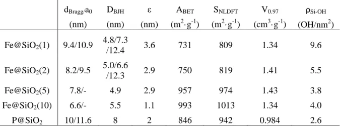
Table 1. Textural properties of Fe@SiO2(r) materials (r = 1, 2, 5, 10) and pristine material,
284
obtained in the absence of CTAF: interlayer distance/unit cell dimension for hexagonal
285
networks dBragg/a0, pore diameter DBJH, wall thickness ε, surface area ABET and SNLDFT,
286
mesopores volume V0.97, and silanols density ρSi-OH.
287 dBragg/a0 (nm) DBJH (nm) ε (nm) ABET (m2·g-1) SNLDFT (m2·g-1) V0.97 (cm3·g-1) ρSi-OH (OH/nm2) Fe@SiO2(1) 9.4/10.9 4.8/7.3 /12.4 3.6 731 809 1.34 9.6 Fe@SiO2(2) 8.2/9.5 5.0/6.6 /12.3 2.9 750 819 1.41 5.5 Fe@SiO2(5) 7.8/- 4.9 2.9 957 974 1.43 3.8 Fe@SiO2(10) 6.6/- 5.5 1.1 993 1013 1.34 4.0 P@SiO2 10/11.6 8 2 846 942 0.984 2.6 288
Further insights in the pore size distribution (PSD) were obtained from nitrogen
289
adsorption/desorption isotherms. Except Fe@SiO2(10), which exhibits a type IV
290
isotherm with one hysteresis loop, characteristic of unimodal mesoporous materials, all
291
materials rather exhibit a type II isotherms with two main steps desorption branch
292
indicating the coexistence of mesopores of different sizes (Figure 1B). On all
293
isotherms, it can be observed that the value of the relative pressure, at which the first
294
capillary condensation occurs is almost the same, between 0.4 and 0.5. Since the p/p0
295
position of the inflection point is related to the pore diameter, according to Kelvin's
296
equation, this observation suggests that all materials have mesopores of about 5 nm in
297
diameter. As a matter of fact, Fe@SiO2(10) has a unimodal distribution of mesopores
298
centered on 5 nm, as shown by the pore diameter distribution obtained by applying the
299
BJH method to the nitrogen desorption isotherms (DBJH, Figure 1C). The second
300
inflection point appears for the other materials at a p/p0 value comprised between 0.7
301
and 0.8, suggesting larger pores. For Fe@SiO2(1) and Fe@SiO2(2), three N2
302
desorption steps can be identified at the following p/p0 intervals: between 0.50 and
303
0.75, between 0.75 and 0.80, and between 0.80 and 0.99, which indicate the existence
304
of mesopores within three ranges of pore diameters. For the Fe@SiO2(5) material, one
305
can observe two zones N2 desorption steps, at p/p0 between 0.50 and 0.80,
306
corresponding to the porosity peak around 5 nm, and at p/p0 between 0.80 and 0.99,
307
corresponding to larger pores (8 < DBJH < 16 nm), where dV·dDBJH-1 is around 0.05
308
cm3·g-1·nm-1. The Fe@SiO2(10) sample shows one N2 adsorption zone (0.50 < p/p0 <
309
0.80) corresponding to the 5 nm pore diameter peak, with noadsorption for p/p0 above
310
0.80. The pore sizes of all materials are wider than the one obtained by using only
311
CTAF as template, without adding the non-ionic P123 surfactant (of 2.4 nm).[42] So is
312
the wall thickness, ε, as it was calculated y the su traction of the pore size DBJH)
313
from the interlayer distance (dBragg) for the wormlike materials and from the cell unit
314
for the hexagonal ordered ones. The surface areas are similar for the hexagonally
315
ordered materials Fe@SiO2(1) and Fe@SiO2(2) on the one hand, and for the wormlike
316
materials Fe@SiO2(5) and Fe@SiO2(10) on the other hand. All materials have high
317
surface areas, ABET and SNLDFT, and total pore volumes V0.97 (Table 1). A sharp
318
increase, of almost 200 m2·g-1, can be noticed between the two series of materials.
319
Therefore, Fe@SiO2(5) and Fe@SiO2(10) might be considered more attractive for
320
catalytic applications, such as in hydrodeoxygenation reactions for example.
322
Figure 1. Textural properties of Fe@SiO2(r) materials (r = nCTAF/nP123 = 1, 2, 5, 10):
323
(A) XRD patterns, (B) N2 adsorption-desorption isotherms, and (C) pore size
324
distribution.
325
326
Figure 2. Transmission electron micrograph of Fe@SiO2(1).
327
3.3. Chemical characterization of Fe@SiO2(r) materials
328
The attenuated total reflectance infrared ATR-IR spectra of Fe@SiO2(r) materials confirms
329
the formation of the silica framework during the sol-gel process and the removal of the
330
organic part of the surfactant after calcination. Characteristic peaks of the stretching and
331
bending vibrations of Si-O-Si, Si-O and Si-OH bonds are present in the 900-1100 cm-1 region,
332
while no peaks of CH2 moieties appear between 2800 and 2900 cm-1 (Figure SI2 left). The
333
ATR spectra also show the presence of OH groups at 1633 cm-1 and at 3200-3700 cm-1 that
334
were assigned to silanol groups and physisorbed water, respectively. Quantitative assessment
335
of silanol densities on the surface of those materials was obtained from BET and TGA
336
analysis (Table 1 and SI3 for the calculation method).
337
All materials exhibit silanols density values higher than for the similarly synthesized
SBA-15-338
like silica, with no CTAF (around 2.50 OH/nm2). This may be due to the existence of iron
339
atoms that hinder silica crosslinking during the polymerization, which may indicate the
340
formation of Si-O H …Fe onds instead of Si-O-Si bonds.
341
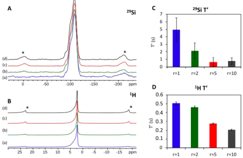
342
Figure 3. Evolution of 29Si (A) and 1H (B) MAS NMR spectra for increasing r values
343
of Fe@SiO2(r) materials: (a) r=1; (b) r=2; (c) r=5 and (d) r=10. Spinning sidebands are
344
marked y * and νMAS
=12.5kHz. Histograms showing the evolution of 29Si (C) and 1H
345
D characteristic T’ spin-lattice relaxation times for increasing r-values in Fe@SiO2(r)
346
materials. Saturation recovery curves have een fitted to “stretched exponential”
347
functions with β 0 5 for 29Si and β 0 74 for 1H. Error bars reflect the 95% confidence
348
interval of the fits.
349
The condensation degree of silica in Fe@SiO2(r) materials could be assessed from 29Si
solid-350
state NMR. Relative proportions of Q2 (SiO2(OH)2 silanols), Q3 (SiO3(OH) silanols), and Q4
351
(SiO4 bonds) units were determined after deconvolution of the peaks at -91, -100 and -110
352
ppm, respectively and all materials exhibit the same condensation degree Q2:Q3:Q4 of 4:24:72
353
(+/-2%). Nevertheless, despite the absence of additional 29Si signals, evidence is found for the
354
presence of paramagnetic Fe. Indeed, the very high magnetic moment of unpaired electrons,
355
located at paramagnetic centers, affects the NMR properties of coupled spins in different ways
356
[68]. Nuclei that are chemically bound, or in the first coordination shell of paramagnetic iron
357
cannot be observed due to extreme paramagnetic broadening. However, above this cutoff
358
radius, nuclear spins become observable despite considerable paramagnetic broadening [69].
359
Under Magic Angle Spinning (MAS) sample rotation, this broadening gives rise to intense
360
sideband patterns in the MAS NMR spectra, which are separated from the isotropic signal by
361
multiples of the rotation frequency [70]. Since the gradual signal loss and broadening occur
362
simultaneously, the boundary between observable and non-observable spins is somewhat
363 ppm -15 -10 -5 0 5 10 15 20 25 * * ppm -200 -150 -100 -50 0 (a) 29Si 1H (b) (c) (d) (a) (b) (c) (d) * * A B 0 0,1 0,2 0,3 0,4 0,5 0,6 r=1 r=2 r=5 r=10 1H T’ T’ ( s) 0 1 2 3 4 5 6 7 r=1 r=2 r=5 r=10 29Si T’ T’ ( s) C D 0.6 0.5 0.4 0.3 0.2 0.1
diffuse (~3.3Å) [71,72], nevertheless it is possible to distinguish between short range effects,
364
inducing signal loss, and medium range effects up to the nanometer scale, inducing line
365
broadening and spin lattice R1 relaxation. Because of the low Fe concentration in the materials
366
studied here, no short-range effects like the decrease in signal intensity or selective loss of
367
pore surface (Q2/Q3) sites with Fe loading could be established. Indeed, even for
368
Fe@SiO2(10), the Fe content remains below 2 wt.% (Table 2). Nevertheless, medium-range
369
effects such as an increase of sideband pattern intensity is indeed observed for 29Si and 1H
370
NMR spectra when the CTAF/P123 ratio increases (Figure 3 A,B). This qualitative result is a
371
consequence of the presence of paramagnetic species and indicates an increase of the average
372
spatial proximity between paramagnetic iron spins and the diamagnetic neighbors, at the
373
subnanometric scale as determined by the pair distribution function analysis (PDF).
374
Additionally, the study of spin lattice R1 relaxation also shows the existence of medium-range
375
paramagnetic effects. Indeed, the 29Si and 1H characteristic T1 relaxation times are low
376
compared to standard SBA-15 type material and therefore semi-quantitative information is
377
best obtained by fitting the peak areas (M) obtained from saturation recovery experiments to a
378
modified “stretched exponential” e uation of characteristic time T’ with β <
379
being the peak area for the longest delay spectrum and a constant equal to 1 if
380
corresponds to the fully relaxed signal [73,74].
381
While spin diffusion commonly induces relaxation of all spins at a same rate β , our data is
382
est fitted for β fixed at 0 5 (Figure SI3) which is typical for relaxation dominated through
383
space dipolar coupling with unpaired electronic spins χ2 is two times lower than for β
384
This result is consistent with a homogeneous iron distribution on the nanometer scale. 1H T1
385
relaxation also shows non-exponential behavior and relaxation curves are best fitted with a
386
higher value of β = 0.74. Despite the fact that NMR samples have been extensively dried to
387
remove 1H from adsorbed water molecules, 1H spin diffusion relaxation is still active and this
388
value of β is typical when mixed relaxation mechanisms act on the spins [75]. As seen on
389
Figure 3 (C,D) characteristic T’ relaxation times decrease when CTAF/P 23 ratio increases
390
This trend suggests an increase in the number of paramagnetic iron sites within the materials.
391
3.4. Characterization of single atom Fe@SiO2(r) materials
A first quantitative assessment of the iron loading, obtained from both ICP-AES elementary
393
analysis, is found to be about 0.56, 0.98, 2.31, and 2.64 wt.% for Fe@SiO2(1), Fe@SiO2(2),
394
Fe@SiO2(5), and Fe@SiO2(10), respectively, as compared to Si (see Table 2 for the iron
395
loading values compared to SiO2). Those results were further confirmed by the elemental
396
mapping obtained by scanning transmission electron microscopy (STEM). The Fe content in
397
these materials, as compared to the Si one, is found to be about 0.8, 1.1, 2.5, and 2.7 wt.% for
398
Fe@SiO2(1), Fe@SiO2(2), Fe@SiO2(5), and Fe@SiO2(10), respectively. Moreover, as it can
399
be seen in Figure 4B,C and SI4, the micrographs show a homogeneous dispersion of iron
400
atoms within the silica matrix, without formation of any agglomerates.
401
UV-Vis diffuse reflectance spectra (Figure SI2 right) allowed us to determine the coordination
402
of iron in the materials. The absorption band at 235 nm, which can be assigned to the charge
403
transfer of pπ–dπ transition etween oxygen and iron in the ferrisilicate material, suggests
404
tetrahedral iron atoms, insulated from each other. In addition, the absence of any absorbance
405
band above 350 nm in the spectrum reveals the absence of octahedral iron ions, and
406
consequently the absence of iron oxide nanoparticles in the Fe@SiO2 materials [76].
407
The absence of nanoparticles was also confirmed by the analysis of the experimental pair
408
distribution function derived from the corresponding total scattering measurements of the
409
materials (Figure 4A). From the PDF diagrams, one can clearly observe well-defined features
410
up to about 7 Å. The rapid damping of PDF oscillations beyond this distance indicates that
411
only isolated subnanometer iron clusters might be formed and are uniformly distributed
412
throughout the samples, with no aggregation. Larger nanoparticles would have resulted a
413
spatial extent of atomic correlations in the PDF diagram.
414
It is obvious that the intensities of the PDF peaks corresponding to the contributions of the Fe
415
atoms increase as the molar ratio r (nCTAF/nP123) increases. The first two PDF peaks located
416
in the r range of 2.0-2.6 Å are characteristic of Fe-O distances, while the PDF peaks located in
417
the range of 3-6 Å can be assigned to the interactions of the iron atoms with the silica pore
418
walls or to Fe-Fe correlations.
419
Finally, it is noteworthy that the presence of the double peak between 2.0 and 2.6 Å indicates
420
two related Fe environments. Further insights on the Fe oxidation, spin states and on Fe-Fe
421
interactions were gathered from magnetic measurements.
422 423
424
Figure 4. Comparison of experimental atomic pair distribution functions (PDFs) in
425
real space, G(r), for Fe@SiO2(r) materials and allocation of the main interatomic
426
distances in the range 2 – 7 Å (A). Relative elemental maps of Fe and Si obtained by
427
EDX in the scanning TEM mode for (B) Fe@SiO2(1), (C) Fe@SiO2(10) (iron in green
428
and silica in red). The scale bare corresponds to 10 nm.
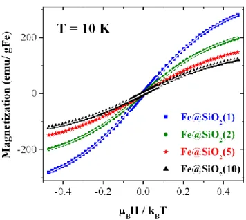
429
The magnetization field dependences of the Fe@SiO2(r) measured at 10K after a first cooling
430
at 15K·min-1 are plotted in Figure 5. These measurements have been subtracted from the
431
diamagnetic contribution of sample holder and pristine P@SiO2(r) silica, as described in SI,
432
and have been scaled with respect to Fe content using the ICP-AES elementary analysis
433
results. They can be fitted by a sum of two Brillouin functions as follow:
434
where is the only fitted parameter giving the proportion of the high spin S=5/2, and
435
are the saturation magnetization of Fe3+
in the high spin and low spin states, respectively
436
( and ), and are the corresponding
437 Brillouin functions (S=5/2, 1/2). 438
The fit with the aforementioned equation has been performed for samples exhibiting
439
a Curie temperature dependence under 79.6 kA/m above 10K (see Figure SI5).
440
A B
441
Figure 5. Field dependence behavior of the magnetization measured at 10K and
442
corrected from the diamagnetic signal for Fe@SiO2(r) (r = 1, 2, 5, 10) samples. It is
443
plotted as a function of the dimensionless parameter where is the Bohr
444
magneton and the Boltzmann constant. The straight lines are fits by the sum of the
445
two Brillouin functions corresponding to S = 5/2 and 1/2.
446
Despite only one parameter is fitted, a very good agreement is obtained between the simple
447
model and the measurements. The fit is not changing while taking into account an additional
448
contribution of Fe2+ (S=2), confirming thus the presence of solely Fe3+ ions. No ferromagnetic
449
contribution is detectable at this scale. The high spin fractions deduced from the fits are
450
reported in Table 2. They are in good agreement with those deduced from the Curie constant
451
(see Figure SI5). No fit with the Brillouin equation has been performed for the Fe@SiO2(5)
452
sample since the temperature dependence of the magnetization deviates from the Curie law
453
below 15 K (see figure SI6). This deviation is attributed to spin crossover towards low spin
454
with decreasing temperature, which occurs below 10 K for other samples (Figure SI7).
455
Nevertheless, the high spin fraction reported in Table 2 is stable with temperature above 10 K
456
(or 15 K for Fe@SiO2(5)) and is then a relevant parameter characterizing the Fe sites in the
457
silica pores. It decreases as the Fe content increases, concomitantly with the decrease of the
458
pore size. Thus, beyond the sharing of Fe spin state according to Si sites or pore sizes, the
459
consistent quantitative analysis in terms of Curie law or Brillouin function without interaction
460
between Fe spins (no Curie-Weiss temperature) supports the assumption of isolated Fe atomic
461
centers that are well dispersed within the materials.
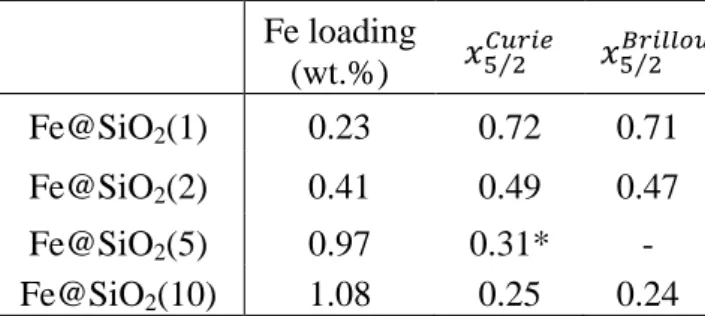
462 463
Table 2. Fe content (wt.%) with respect to the total samples mass used to scale the
464
magnetization. Fraction of Fe3+ spins in the high spin state (5/2) deduced from the
465
temperature dependence of magnetization (Curie law) or field dependence of magnetization
466 measured at 10 K. 467 Fe loading (wt.%) Fe@SiO2(1) 0.23 0.72 0.71 Fe@SiO2(2) 0.41 0.49 0.47 Fe@SiO2(5) 0.97 0.31* - Fe@SiO2(10) 1.08 0.25 0.24
*No fit with Brillouin functions has been performed for Fe@SiO2(5) as it deviates from the Curie law below
468
15K. For this sample, the fit with the Curie law has been performed in the 15-30 K.
469 470
3.5. DFT calculations
471
Several structural configurations of the Fe/SiO2 system were calculated in order to determine
472
the most favorable adsorption position (top vs bridge, Figure 6) as well as the spin state,
473
without or under geometrical constraints (2% contraction of the silica surface along the x and
474
y directions), as in mesopores. The calculations were firstly started from reasonable
475
estimations at various adsorption positions (top, bridge) on surfaces with various silanol
476
densities (SiO2-7.2, SiO2-4.6 and SiO2-3.3) [64,65]. For each configuration, two sets of
477
calculations were performed for the Low-Spin (LS) and High-Spin (HS) states of iron.
478
479
Figure 6. Panels showing the single iron atom adsorbed on amorphous silica surface with a
480
silanol density of 4.6 OH/nm2 at top (left) and bridge (right) positions, respectively. For the
481
top adsorption, the equilibrium distance between the iron atom and the substrate is found to be
482
1.81 Å in HS and 1.78 Å in LS (left). For the bridge adsorption, in the HS state, the
483
equilibrium iron-surface distances were found to be 1.99 and 1.85 Å for both oxygen atoms,
484
whereas in the LS state, these distances became 1.85 and 1.81 Å, respectively (right).
485
The Fe atom was adsorbed on the silica surface through its oxygen atoms by removing the
486
corresponding hydrogen atoms. Figure 6 shows the single iron atom adsorbed on the typical
silica surface with a silanol coverage equal to 4.6 OH per nm2 at top (left panel) and bridge
488
(right panel) positions. For the top positions, the HS state magnetic moment of iron is 4 97 μB
489
S 5/2 while the one of the LS state is 00 μB S /2 , which correspond to Fe3+
.
490
However, the HS and LS state magnetic moments of the iron in the bridge positions are found
491
to e 4 00 μB S 2 and 0 00 μB S 0 , respectively, which are the HS and LS states of
492
Fe2+. It is noteworthy that, for the various silica surfaces, the calculations show that the
493
adsorption of the iron atom at top positions has always the lowest total energy. Thus, the Fe3+
494
oxidation state is the most favorable whatever the silanols density, in agreement with
495
experimental findings where no Fe2+ contribution is observed. Nevertheless, the calculations
496
show that, in the absence of geometrical constraints, the adsorption of the single iron atom on
497
various amorphous silica-surface stabilizes the HS state. This result is in contrast with
498
magnetic results where a contribution of low spins had to be considered. Such low spin state
499
is however not surprising in presence of porous materials where strains are expected.
500
Therefore, additional DFT calculations were performed starting from optimized top positions
501
at high and low spin, while taking into account geometrical constraints. The contraction of the
502
geometries along the x and y directions has been set to mimic the fact that the silica surface is
503
not perfectly planar but slightly curved which is modeled in our simulations by a pressure.
504
The choice of a contraction value of 2% has been done as a follow: the calculations with an
505
applied pressure smaller than 2% does not show a significant effect on the studied properties.
506
Also, pressures exceeding 2% are probably unrealistic and could give rise to unphysical
507
phenomena. For high silanols densities (7.2 and 4.6 OH/nm²), our calculations (Table SI3)
508
confirm the coexistence of LS and HS Fe3+ species determined from magnetic measurements
509
(Table 2). For low silanols densities (3.3 OH/nm²), the LS and HS calculations converged to
510
the same magnetic state (LS with a magnetic moment of 1 µB). This result is in line with the
511
experimental trend observed in Table 2 showing that the relative amount of LS Fe3+ increase
512
when decreasing the silanol density. In conclusion, DFT calculations confirmed the
513
experimental results obtained from magnetic measurements, indicating a mixture of HS and
514
LS Fe3+ species.
515
4. Conclusion
516
In this study, we demonstrated that single iron atoms-supported materials (Fe/SiO2) can be
517
prepared by hydrothermal synthesis using mixed non-ionic/metallosurfactants as templates.
518
The non-ionic Pluronic P123 surfactant allows controlling the structural and textural
properties of the silica framework while the ferrosurfactant acts as a metal donor, in addition
520
to its role of porogen. The iron loading in the final materials depends on the molar ratio of
521
surfactants and can be accurately tuned, up to 1wt% (0.15 Fe atoms/nm2). Pair distribution
522
function analysis, STEM mapping and magnetic measurements demonstrated the absence of
523
any particle or cluster. Experimental data showed that the Fe species are Fe3+, in agreement
524
with the DFT calculations. Those materials proved a good distribution of iron atoms on the
525
silica surface, with increased number of active sites, which might find straightforward
526
applications in catalysis [2–7].
527
Acknowledgements
528
Authors would like to thank S. Parant for technical assistance with spectroscopic
529
measurements, C. Gardiennet and G. Kervern for useful discussions on NMR. Authors
530
acknowledge the Center of Magnetism of the Institute Jean Lamour for magnetic
531
measurements facilities and the X-ray diffraction platform PMD²X of the Institut Jean Barriol
532
for SAXS measurements time. The authors acknowledge financial support from the
533
"Mira elle+" project of the "Lorraine Université d'Excellence" Investissements d’avenir –
534
ANR), CPER Enerbatin and PHC CEDRE Future Materials. SG, SL and MB also
535
acknowledge financial support through the COMETE project (COnception in silico de
536
Matériaux pour l’EnvironnemenT et l’Energie co-funded by the European Union under the
537
program "FEDER-FSE Lorraine et Massif des Vosges 2014-2020". HPC resources have been
538
provided by GENCI-CCRT (Grant and No. A0060910433).
539
Author Contributions
540
The manuscript was written through contributions of all authors.
541
Funding Sources
542
FEDER, LUE, ANR, CNRS Lebanon, Lebanese University.
543
Abbreviations
544
CTAF cetyltrimethylammoniumtrichloromonobromoferrate, DFT Density Functional Theory,
545
STEM scanning transmission electron microscopy.
546
Supplementary data
1. Structural properties of pristine SBA-15-like material, obtained in the absence of CTAF; 2.
548
Spectroscopic measurements (ATR and UV-Vis); 3. Thermogravimetric analysis; 4. NMR; 5.
549
Elemental cartography; 6. Magnetic measurements (substraction of the diamagnetic signal and
550
low temperature spin crossover) and 7. DFT calculations.
551 552
References
553
[1] M. Li, Z. Zhao, T. Cheng, A. Fortunelli, C.-Y. Chen, R. Yu, Q. Zhang, L. Gu, B.V.
554
Merinov, Z. Lin, E. Zhu, T. Yu, Q. Jia, J. Guo, L. Zhang, W.A. Goddard, Y. Huang, X.
555
Duan, Ultrafine jagged platinum nanowires enable ultrahigh mass activity for the oxygen
556
reduction reaction, Science. 354 (2016) 1414–1419.
557
https://doi.org/10.1126/science.aaf9050.
558
[2] P. Chen, T. Zhou, L. Xing, K. Xu, Y. Tong, H. Xie, L. Zhang, W. Yan, W. Chu, C. Wu,
559
Y. Xie, Atomically Dispersed Iron-Nitrogen Species as Electrocatalysts for Bifunctional
560
Oxygen Evolution and Reduction Reactions, Angew. Chem. 129 (2017) 625–629.
561
https://doi.org/10.1002/ange.201610119.
562
[3] J.M. Thomas, R. Raja, The advantages and future potential of single-site heterogeneous
563
catalysts, Top. Catal. 40 (2006) 3–17. https://doi.org/10.1007/s11244-006-0105-7.
564
[4] X.-F. Yang, A. Wang, B. Qiao, J. Li, J. Liu, T. Zhang, Single-Atom Catalysts: A New
565
Frontier in Heterogeneous Catalysis, Acc. Chem. Res. 46 (2013) 1740–1748.
566
https://doi.org/10.1021/ar300361m.
567
[5] A. Wang, J. Li, T. Zhang, Heterogeneous single-atom catalysis, Nat. Rev. Chem. 2
568
(2018) 65–81. https://doi.org/10.1038/s41570-018-0010-1.
569
[6] H. Zhang, G. Liu, L. Shi, J. Ye, Single-Atom Catalysts: Emerging Multifunctional
570
Materials in Heterogeneous Catalysis, Adv. Energy Mater. 8 (2018) 1701343.
571
https://doi.org/10.1002/aenm.201701343.
572
[7] Y. Chen, S. Ji, C. Chen, Q. Peng, D. Wang, Y. Li, Single-Atom Catalysts: Synthetic
573
Strategies and Electrochemical Applications, Joule. 2 (2018) 1242–1264.
574
https://doi.org/10.1016/j.joule.2018.06.019.
575
[8] J. Jones, H. Xiong, A.T. DeLaRiva, E.J. Peterson, H. Pham, S.R. Challa, G. Qi, S. Oh,
576
M.H. Wiebenga, X.I. Pereira Hernandez, Y. Wang, A.K. Datye, Thermally stable
single-577
atom platinum-on-ceria catalysts via atom trapping, Science. 353 (2016) 150–154.
578
https://doi.org/10.1126/science.aaf8800.
579
[9] S. Sun, G. Zhang, N. Gauquelin, N. Chen, J. Zhou, S. Yang, W. Chen, X. Meng, D.
580
Geng, M.N. Banis, R. Li, S. Ye, S. Knights, G.A. Botton, T.-K. Sham, X. Sun,
Single-581
atom Catalysis Using Pt/Graphene Achieved through Atomic Layer Deposition, Sci.
582
Rep. 3 (2013). https://doi.org/10.1038/srep01775.
583
[10] H. Yan, H. Cheng, H. Yi, Y. Lin, T. Yao, C. Wang, J. Li, S. Wei, J. Lu, Single-Atom Pd
584
1 /Graphene Catalyst Achieved by Atomic Layer Deposition: Remarkable Performance
585
in Selective Hydrogenation of 1,3-Butadiene, J. Am. Chem. Soc. 137 (2015) 10484–
586
10487. https://doi.org/10.1021/jacs.5b06485.
587
[11] J. Lin, A. Wang, B. Qiao, X. Liu, X. Yang, X. Wang, J. Liang, J. Li, J. Liu, T. Zhang,
588
Remarkable Performance of Ir1/FeOx Single-Atom Catalyst in Water Gas Shift Reaction, 589
J. Am. Chem. Soc. 135 (2013) 15314–15317. https://doi.org/10.1021/ja408574m.
[12] B. Qiao, L. Liu, J. Zhang, Y. Deng, Preparation of highly effective ferric hydroxide
591
supported noble metal catalysts for CO oxidations: From gold to palladium, J. Catal. 261
592
(2009) 241–244. https://doi.org/10.1016/j.jcat.2008.11.012.
593
[13] B. Qiao, A. Wang, X. Yang, L.F. Allard, Z. Jiang, Y. Cui, J. Liu, J. Li, T. Zhang,
Single-594
atom catalysis of CO oxidation using Pt1/FeOx, Nat. Chem. 3 (2011) 634–641.
595
https://doi.org/10.1038/nchem.1095.
596
[14] F. Li, Y. Li, X.C. Zeng, Z. Chen, Exploration of High-Performance Single-Atom
597
Catalysts on Support M1/FeOx for CO Oxidation via Computational Study, ACS Catal. 5 598
(2015) 544–552. https://doi.org/10.1021/cs501790v.
599
[15] B. Qiao, J.-X. Liang, A. Wang, C.-Q. Xu, J. Li, T. Zhang, J.J. Liu, Ultrastable
single-600
atom gold catalysts with strong covalent metal-support interaction (CMSI), Nano Res. 8
601
(2015) 2913–2924. https://doi.org/10.1007/s12274-015-0796-9.
602
[16] B. Qiao, J. Liu, Y.-G. Wang, Q. Lin, X. Liu, A. Wang, J. Li, T. Zhang, J. (Jimmy) Liu,
603
Highly Efficient Catalysis of Preferential Oxidation of CO in H2-Rich Stream by Gold
604
Single-Atom Catalysts, ACS Catal. 5 (2015) 6249–6254.
605
https://doi.org/10.1021/acscatal.5b01114.
606
[17] P. Liu, Y. Zhao, R. Qin, S. Mo, G. Chen, L. Gu, D.M. Chevrier, P. Zhang, Q. Guo, D.
607
Zang, B. Wu, G. Fu, N. Zheng, Photochemical route for synthesizing atomically
608
dispersed palladium catalysts, Science. 352 (2016) 797–800.
609
https://doi.org/10.1126/science.aaf5251.
610
[18] P. Yin, T. Yao, Y. Wu, L. Zheng, Y. Lin, W. Liu, H. Ju, J. Zhu, X. Hong, Z. Deng, G.
611
Zhou, S. Wei, Y. Li, Single Cobalt Atoms with Precise N-Coordination as Superior
612
Oxygen Reduction Reaction Catalysts, Angew. Chem. 128 (2016) 10958–10963.
613
https://doi.org/10.1002/ange.201604802.
614
[19] Y. Chen, S. Ji, Y. Wang, J. Dong, W. Chen, Z. Li, R. Shen, L. Zheng, Z. Zhuang, D.
615
Wang, Y. Li, Isolated Single Iron Atoms Anchored on N-Doped Porous Carbon as an
616
Efficient Electrocatalyst for the Oxygen Reduction Reaction, Angew. Chem. 129 (2017)
617
7041–7045. https://doi.org/10.1002/ange.201702473.
618
[20] L. Yang, D. Cheng, H. Xu, X. Zeng, X. Wan, J. Shui, Z. Xiang, D. Cao, Unveiling the
619
high-activity origin of single-atom iron catalysts for oxygen reduction reaction, Proc.
620
Natl. Acad. Sci. 115 (2018) 6626–6631. https://doi.org/10.1073/pnas.1800771115.
621
[21] H. Fei, J. Dong, Y. Feng, C.S. Allen, C. Wan, B. Volosskiy, M. Li, Z. Zhao, Y. Wang,
622
H. Sun, P. An, W. Chen, Z. Guo, C. Lee, D. Chen, I. Shakir, M. Liu, T. Hu, Y. Li, A.I.
623
Kirkland, X. Duan, Y. Huang, General synthesis and definitive structural identification
624
of MN4C4 single-atom catalysts with tunable electrocatalytic activities, Nat. Catal. 1
625
(2018) 63–72. https://doi.org/10.1038/s41929-017-0008-y.
626
[22] S. Back, J. Lim, N.-Y. Kim, Y.-H. Kim, Y. Jung, Single-atom catalysts for CO2
627
electroreduction with significant activity and selectivity improvements, Chem. Sci. 8
628
(2017) 1090–1096. https://doi.org/10.1039/C6SC03911A.
629
[23] M. Flytzani-Stephanopoulos, B.C. Gates, Atomically Dispersed Supported Metal
630
Catalysts, Annu. Rev. Chem. Biomol. Eng. 3 (2012) 545–574.
631
https://doi.org/10.1146/annurev-chembioeng-062011-080939.
632
[24] C. Nozaki, C.G. Lugmair, A.T. Bell, T.D. Tilley, Synthesis, Characterization, and
633
Catalytic Performance of Single-Site Iron(III) Centers on the Surface of SBA-15 Silica,
634
J. Am. Chem. Soc. 124 (2002) 13194–13203. https://doi.org/10.1021/ja020388t.
635
[25] B. Hu, N.M. Schweitzer, G. Zhang, S.J. Kraft, D.J. Childers, M.P. Lanci, J.T. Miller,
636
A.S. Hock, Isolated FeII on Silica As a Selective Propane Dehydrogenation Catalyst,
637
ACS Catal. 5 (2015) 3494–3503. https://doi.org/10.1021/acscatal.5b00248.
[26] R.N. Olcese, M. Bettahar, D. Petitjean, B. Malaman, F. Giovanella, A. Dufour,
Gas-639
phase hydrodeoxygenation of guaiacol over Fe/SiO2 catalyst, Appl. Catal. B Environ.
640
115–116 (2012) 63–73. https://doi.org/10.1016/j.apcatb.2011.12.005.
641
[27] N. Wang, W. Chu, T. Zhang, X.S. Zhao, Synthesis, characterization and catalytic
642
performances of Ce-SBA-15 supported nickel catalysts for methane dry reforming to
643
hydrogen and syngas, Int. J. Hydrog. Energy. 37 (2012) 19–30.
644
https://doi.org/10.1016/j.ijhydene.2011.03.138.
645
[28] D.J. Kim, B.C. Dunn, F. Huggins, G.P. Huffman, M. Kang, J.E. Yie, E.M. Eyring,
SBA-646
15-Supported Iron Catalysts for Fischer−Tropsch Production of Diesel Fuel, Energy
647
Fuels. 20 (2006) 2608–2611. https://doi.org/10.1021/ef060336f.
648
[29] G. Prieto, A. Martínez, R. Murciano, M.A. Arribas, Cobalt supported on
649
morphologically tailored SBA-15 mesostructures: The impact of pore length on metal
650
dispersion and catalytic activity in the Fischer–Tropsch synthesis, Appl. Catal. Gen. 367
651
(2009) 146–156. https://doi.org/10.1016/j.apcata.2009.08.003.
652
[30] L.A. Cano, M.V. Cagnoli, J.F. Bengoa, A.M. Alvarez, S.G. Marchetti, Effect of the
653
activation atmosphere on the activity of Fe catalysts supported on SBA-15 in the
654
Fischer–Tropsch Synthesis, J. Catal. 278 (2011) 310–320.
655
https://doi.org/10.1016/j.jcat.2010.12.017.
656
[31] Y. Sun, S. Walspurger, J.-P. Tessonnier, B. Louis, J. Sommer, Highly dispersed iron
657
oxide nanoclusters supported on ordered mesoporous SBA-15: A very active catalyst for
658
Friedel–Crafts alkylations, Appl. Catal. Gen. 300 (2006) 1–7.
659
https://doi.org/10.1016/j.apcata.2005.10.029.
660
[32] B. Karimi, S. Abedi, J.H. Clark, V. Budarin, Highly Efficient Aerobic Oxidation of
661
Alcohols Using a Recoverable Catalyst: The Role of Mesoporous Channels of SBA-15
662
in Stabilizing Palladium Nanoparticles, Angew. Chem. Int. Ed. 45 (2006) 4776–4779.
663
https://doi.org/10.1002/anie.200504359.
664
[33] X. Liu, A. Wang, X. Wang, C.-Y. Mou, T. Zhang, Au–Cu Alloy nanoparticles confined
665
in SBA-15 as a highly efficient catalyst for CO oxidation, Chem. Commun. (2008) 3187.
666
https://doi.org/10.1039/b804362k.
667
[34] F. Rajabi, S. Naserian, A. Primo, R. Luque, Efficient and Highly Selective Aqueous
668
Oxidation of Sulfides to Sulfoxides at Room Temperature Catalysed by Supported Iron
669
Oxide Nanoparticles on SBA-15, Adv. Synth. Catal. 353 (2011) 2060–2066.
670
https://doi.org/10.1002/adsc.201100149.
671
[35] H. Huang, Y. Ji, Z. Qiao, C. Zhao, J. He, H. Zhang, Preparation, Characterization, and
672
Application of Magnetic Fe-SBA-15 Mesoporous Silica Molecular Sieves, J. Autom.
673
Methods Manag. Chem. 2010 (2010) 323509. https://doi.org/10.1155/2010/323509.
674
[36] Y. Li, Z. Feng, Y. Lian, K. Sun, L. Zhang, G. Jia, Q. Yang, C. Li, Direct synthesis of
675
highly ordered Fe-SBA-15 mesoporous materials under weak acidic conditions,
676
Microporous Mesoporous Mater. 84 (2005) 41–49.
677
https://doi.org/10.1016/j.micromeso.2005.05.021.
678
[37] J.M. Campelo, D. Luna, R. Luque, J.M. Marinas, A.A. Romero, Sustainable Preparation
679
of Supported Metal Nanoparticles and Their Applications in Catalysis, ChemSusChem.
680
2 (2009) 18–45. https://doi.org/10.1002/cssc.200800227.
681
[38] A. Barau, V. Budarin, A. Caragheorgheopol, R. Luque, D.J. Macquarrie, A. Prelle, V.S.
682
Teodorescu, M. Zaharescu, A Simple and Efficient Route to Active and Dispersed Silica
683
Supported Palladium Nanoparticles, Catal. Lett. 124 (2008) 204–214.
684
https://doi.org/10.1007/s10562-008-9465-x.
685
[39] N.C. King, R.A. Blackley, W. Zhou, D.W. Bruce, The preparation by true liquid crystal
686
templating of mesoporous silicates containing nanoparticulate metals, Chem. Commun.
687
(2006) 3411. https://doi.org/10.1039/b607470g.