HAL Id: hal-03044103
https://hal.archives-ouvertes.fr/hal-03044103
Submitted on 7 Dec 2020
HAL is a multi-disciplinary open access
archive for the deposit and dissemination of
sci-entific research documents, whether they are
pub-lished or not. The documents may come from
teaching and research institutions in France or
abroad, or from public or private research centers.
L’archive ouverte pluridisciplinaire HAL, est
destinée au dépôt et à la diffusion de documents
scientifiques de niveau recherche, publiés ou non,
émanant des établissements d’enseignement et de
recherche français ou étrangers, des laboratoires
publics ou privés.
by ligand-capped Ru nanoparticles
Nuria Romero, Renan Barrach Guerra, Laia Gil, Samuel Drouet, Ivan
Salmeron-Sànchez, Ona Illa, Karine Philippot, Mirco Natali, Jordi
García-Antón, Xavier Sala
To cite this version:
Nuria Romero, Renan Barrach Guerra, Laia Gil, Samuel Drouet, Ivan Salmeron-Sànchez, et al.. TiO
2 -mediated visible-light-driven hydrogen evolution by ligand-capped Ru nanoparticles. Sustainable
Energy & Fuels, Royal Society of Chemistry, 2020, 4 (8), pp.4170-4178. �10.1039/D0SE00446D�.
�hal-03044103�
ARTICLE
a.Departament de Química, Universitat Autònoma de Barcelona, 08193-Bellaterra,
Barcelona, Spain. E-mail: [email protected] ; [email protected] b.UNICAMP - Instituto de Química, I-102, Postal box 6154 CEP 13083-970 Cidade
Universitária - Campinas, SP, Brasil.
c. Dr. Samuel Drouet, Dr. Karine Philippot, LCC-CNRS, Université de Toulouse, CNRS,
UPS, 205, route de Narbonne, F-31077 Toulouse, France.
d.Dipartimento di Scienze Chimiche e Farmaceutiche, Università degli Studi di
Ferrara, Via L. Borsari, 46, 44121 Ferrara, Italy. E-mail: [email protected]
† Electronic Supplementary Information (ESI) available:. See DOI: 10.1039/x0xx00000x
Received 00th January 20xx, Accepted 00th January 20xx DOI: 10.1039/x0xx00000x
TiO
2-Mediated Visible-Light-Driven Hydrogen Evolution by
Ligand-Capped Ru Nanoparticles
Nuria Romero,[a] Renan Barrach Guerra,[b] Laia Gil,[a] Samuel Drouet,[c] Ivan Salmeron-Sànchez,[a]
Ona Illa,[a] Karine Philippot,[c] Mirco Natali,[d]* Jordi García-Antón,[a]* Xavier Sala.[a]*
Ru nanomaterials have recently emerged as potential substitutes for classical Pt-based cathodes in the hydrogen evolution reaction (HER). In this regard, nanoparticle surface-functionalization through the so-called organometallic approach is a promising strategy towards the synthesis of tailored highly active and durable HER (photo)electrocatalyst of limitless tunability. Herein, efficient (turnover numbers over 480 molH2 · molRu-1 and turnover frequencies of 21.5 molH2 · h-1 · molRu -1) and durable (> 100 h) visible-light-driven hydrogen evolution has been achieved at neutral pH with a ternary hybrid
nanomaterial combining 4-phenylpyridine-capped Ru nanoparticles (RuPP), TiO2 nanocrystals and [Ru(bpy)2
(4,4’-(PO3H2)2(bpy))]Cl2 (RuP) using triethanolamine (TEOA) as sacrificial electron-donor. Photophysical analysis by means of
transient absorption spectroscopy has been performed in order to shed light on the kinetics of the electron transfer events and to identify the rate-determining step of the overall photocatalytic process. TiO2 is shown to have a key role as (1)
support aiding the dispersion of the photocatalyst and limiting its agglomeration under turnover conditions and, (2) electron-transfer mediator enabling the efficient electron-communication between the catalyst and the anchored molecular photoabsorber. Finally, the evolution and fate of the photocatalyst on long-term HER photocatalysis are
thoroughly analyzed.
Introduction
The effects of global warming, triggered by the massive combustion of fossil resources, threaten our societal lifestyle and urge the development of sustainable energy conversion schemes. Inspired by the light-driven production of biomolecules in photosynthetic processes, storing sunlight energy in the chemical bonds of a fuel is a promising strategy known as artificial photosynthesis.[1] In this
regard, the sustainable production of molecular hydrogen through sunlight-driven water splitting (hν-WS) is a key process as the obtained H2 can be directly used as a fuel or employed as a reagent
for other relevant routes such as the production of green methanol through CO2-based processes.[2]
In a division-of-labor approach for h-WS, photoelectrochemical (PEC) cells represent a compromise between technological maturity and cost, relying on the development of individual photoanodes and photocathodes.[3,4] In h-WS PEC cells, solar energy is collected
by light-harvesting components that enable light-induced charge separation after excitation, water serves as an electron and proton donor at the photoanode and protons are converted into
dihydrogen at the photocathode. Thus, the development of efficient photocatalytic systems for the hydrogen evolution reaction (HER) is a central matter in h-WS. In this endeavor, appropriate HER photocatalysts and photoabsorber (PA) molecules/materials must be developed and properly combined in order to minimize undesired charge recombination processes.
Even if relatively low-demanding from a thermodynamic point of view (E0(H2O/H2) = -0.41 V vs. NHE at pH 7), the two-electron
reduction of protons to molecular hydrogen is kinetically sluggish and requires the use of appropriate catalysts. Pt, with low working overpotentials and extremely high intrinsic activities (due to the ideal Pt-H adsorption energy), is regularly the metal of choice.[5]
Nevertheless, heterogeneous Pt-based systems suffer from (a) important corrosion under alkaline conditions, and (b) the scarcity and prohibitive price of the metal that makes it unsuitable for practical large-scale applications. In view of the limited HER performance of most earth-abundant systems,[6] Ru nanomaterials
have recently emerged as potential substitutes to Pt-based cathodes.[7–9] Ru-based systems are an alternative to reduce the
cost of the catalyst (since the price of Ru is ¼th that of Pt) but mainly
to overcome the stability issues in alkaline conditions of the latter. In this regard, we have recently highlighted the power of the organometallic approach[10] for the tailored development of
ligand-capped Ru nanoparticles (NPs) that display narrow size-distribution and controllable surface properties, as well as high electrocatalytic
performance and long-term durability for HER.[11,12]
Despite their relevant electrocatalytic performance, the number of efficient HER photocatalytic systems based on Ru nanocatalysts is still very limited.[9] Together with their frequent agglomeration
ARTICLE Journal Name
2 | J. Name., 2012, 00, 1-3 This journal is © The Royal Society of Chemistry 20xx
state in PA (i.e. [Ru(bpy)3]2+ derivatives, see Chart 1) / Ru NP
systems is typically hampered by non-desired back-electron transfer processes from the PA excited state.[14] Thus, together with a
sacrificial electron-donor, the use of an electron relay (i.e. methyl viologen) is often required. Relevant exceptions were reported by Fukuzumi and co-workers using organic donor-acceptor linked dyads (i.e. the 2-phenyl-4-(1-naphthyl)-quinolinium ion, QuPh+-NA,
see Chart 1) which afford long-lived charge-separated states and efficient HER photocatalytic systems in combination with transition-metal based NPs such as Ru NPs.[14–16] However, even if the
photocatalytic performance of the QuPh+-NA/Ru NPs system
compares well with that of Pt-based systems under similar conditions, the organic dyad absorbs light mainly in the UV part of the electromagnetic spectrum and, due to its very low solubility in water, requires addition of organic solvents (i.e. MeCN) to the reaction media.
Herein we report our approach to attain efficient and durable visible-light-driven hydrogen evolution at neutral pH. This approach is based on the use of a ternary hybrid nanomaterial that combines TiO2-supported 4-phenylpyridine-capped Ru NPs as photocatalyst
with an anchorable ruthenium trisbipyridine-based PA (RuP, Chart 1), and triethanolamine (TEOA) as SED. A detailed understanding of the electron transfer kinetics within the photochemical system examined is provided by time-resolved optical spectroscopy measurements, which evidence the key role of TiO2 as
electron-relay and highlight the electron transfer from the semiconductor to the Ru NPs as the rate-determining step prior to hydrogen evolution.
Results and discussion
Synthesis and characterization
The hybrid photocatalysts have been prepared in a three-step process (Scheme 1): 1) the organometallic approach for the synthesis of nanostructures, then 2) their deposition onto the TiO2 surface by impregnation from a colloidal solution and
finally 3) their controlled surface-oxidation. First, following our recent report,[12] 4-phenylpyridine (PP) stabilized ruthenium
NPs (RuPP) were synthesized by decomposing the [Ru(cod)(cot)] (cod = 1,5-cyclooctadiene; cot = 1,3,5-cyclooctatriene) complex in THF under H2 atmosphere (3 bar)
at room temperature (r.t.), using PP as stabilizing ligand ([PP]/[Ru]= 0.2 molar equivalent). TEM analysis of the crude solution showed well-dispersed RuPP NPs of 1.4 ± 0.3 nm average diameter (by considering the smallest dimension) with a narrow size distribution (Figure 1a). Next, the crude colloidal RuPP solution was added to TiO2 (at 2 and 10 wt.% Ru). The
obtained slurry was stirred for 4 days at r.t. in the dark and under argon atmosphere. Then the solvent was filtered off
which led to light/dark gray solids RuPP(2%)-TiO2 and
RuPP(10%)-TiO2, respectively, which were washed with
hexane and dried under vacuum. Finally, the obtained nanomaterials were gradually exposed to air by slow oxygen diffusion at r.t. into a screw cap vial in which the solids were introduced under Ar, giving rise to the corresponding
Ru@RuO2PP-TiO2 nanohybrids (Scheme 1). This final
protection step was performed in a controlled manner due to the known high reactivity of RuPP NPs when exposed to air,
which alters their morphology and decreases their catalytic
performance in HER.[12] The so-obtained hybrid nanomaterials
were characterized by a set of complementary techniques.
Chart 1. Molecular photoabsorbers used in this work.
Transmission electron microscopy (TEM) characterization of the RuPP(2%)-TiO2 and RuPP(10%)-TiO2 hybrids was carried
out after depositing a drop of the slurry onto a carbon-covered copper grid. The deposition of small NPs onto the surface of TiO2 crystals was observed for RuPP(2%)-TiO2 with no RuPP
NPs visible outside of the grains (Figure S1a in the Supporting Information). Both isolated and supported NPs were observed for the RuPP(10%)-TiO2 sample (Figure S1b). Therefore, the
study was continued only at low metal content, namely with
RuPP(2%)-TiO2 sample. After a protection step by reacting with
air, the Ru@RuO2PP-TiO2 sample presented a Ru metal
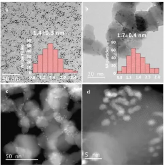
content of 1.6 wt.% as determined by ICP-OES analysis. Besides, HRTEM, HAADF-STEM (Figures 1b-d) and EDX (Figure S2) analyses on this sample evidenced the unaltered morphology and dispersion of the NPs in the hybrid materials after surface-oxidation. Fast Fourier Transform (FFT) electron diffraction patterns showed particles with crystalline character. Interplanar distances measured are indicative of the presence of both Ru and RuO2 phases (Figure S3). The mean
average diameter of the Ru/RuO2 NPs in the Ru@RuO2PP-TiO2
sample calculated from HRTEM images (Figure 1b) is of 1.7 ± 0.4 nm. The chemical composition of the Ru@RuO2PP-TiO2
sample was further analyzed by X-ray photoelectron spectroscopy (XPS). The mixture of metallic Ru and RuO2 was
confirmed (Figure S4), with Ru 3d5/2 peaks centered at 279.8
eV (metallic Ru) and 280.8 eV (RuO2).
Photocatalytic hydrogen evolution
The photocatalytic performance of the nanomaterials towards the HER was evaluated in 0.2 M TEOA aqueous solution at pH 7 (25 °C) and, unless otherwise stated, under visible-light illumination ( > 400 nm) calibrated to 1 sun intensity (see Figure S5 for a schematic representation of the employed setup). Together with TEOA as SED,[17] the three molecular PAs
shown in Chart 1 have been assayed in combination with
Ru@RuO2PP and Ru@RuO2PP-TiO2 as HER (photo)catalysts. A
summary of the obtained photocatalytic results can be found in Table 1.
Scheme 1. Synthesis of Ru@RuO2PP-TiO2.
Figure 1. a) TEM image of RuPP nanoparticles and corresponding size
histogram, b) TEM image of Ru@RuO2PP-TiO2 and corresponding size
histogram, c) and d) HAADF-STEM images of Ru@RuO2PP-TiO2. Initially, the photocatalytic performance of non-supported
Ru@RuO2PP was assessed. The visible-light irradiation of a
colloidal solution of Ru@RuO2PP, TEOA and a PA among
[Ru(bpy)3]3+, RuP or QuPh+-NA showed no H2 evolution (Figure
2a and Table 1, entries 1-3). The addition of methyl viologen (MV2+, entries 4-5) as an electron mediator did not lead to
significant improvements, with H2 evolution below 3.5 µmol
after 10 h of irradiation. The observed induction period may be ascribed to saturation of the aqueous solution prior to H2
diffusion to the headspace (where the gas is measured), although, as previously reported,[12] the reduction of NP RuO
2
surface sites to more active metallic Ru under reductive conditions is not discarded. The low performance of the unsupported systems can be ascribed both to the low
dispersibility and progressive aggregation of Ru@RuO2PP
nanoparticles observed in aqueous media and to the inefficient charge accumulation within the nanoparticulate Ru catalysts leading to unfavorable charge recombination pathways.[14] The latter hypothesis will be supported later on
by photophysical data (see below). Finally, in contrast with the
results of Fukuzumi and co-workers with the QuPh+-NA
donor-acceptor dyad (max = 340 nm) combined with Ru NPs,[14–16]
when the Ru@RuO2PP / QuPh+-NA system was irradiated with
the full solar spectrum (no UV filter applied in a quartz cell) no H2 production was observed (Figure 2a and Table 1, entry 3).
Thus, the results gathered with the unsupported Ru@RuO2PP
nanomaterial highlight the need to improve the stability of this system in aqueous media and probably also the electronic communication/charge separation between it and visible-light PAs such as [Ru(bpy)3]2+ or its derivatives. The effect of
semiconducting TiO2 as both NP support and/or
electron-relay[18–20] was then evaluated.
Figure 2. . Photocatalytic hydrogen evolution in 4 mL of a 0.2 M TEOA
aqueous solution of: (a) Unsupported Ru@RuO2PP with different PA
(0.1 mM); (b) Supported Ru@RuO2PP-MO2 (M= Ti, Zr) with 0.1 mM
[Ru(bpy)3]2+, 0.1 mM RuP, no PA, and the corresponding TiO2-RuP
blank; (c) Optimization of RuP PA concentration in the photocatalytic hydrogen evolution of Ru@RuO2PP-TiO2 (2 mg); (d) Study of the
Ru@RuO2PP-TiO2 concentration at the optimized Ru@RuO2PP-TiO2 /
RuP ratio.
The photocatalytic experiments with Ru@RuO2PP-TiO2 were
performed in a pH neutral TEOA aqueous solution under visible light irradiation ( > 400 nm) and in the presence or absence of [Ru(bpy)3]2+ and RuP as PAs (Table 1, entries 6-8).
As shown in Figure 2b, hydrogen evolution was only observed in the presence of the RuP PA. H2 production also happened
when bare TiO2 was combined with RuP under visible light
irradiation, even if at extremely slow reaction rates (Table 1, entry 10). These results emphasize the major role of both the TiO2 support and the RuP PA phosphonic acid anchors in
facilitating electron transfer and thus enabling HER
photocatalysis. In contrast to non-supported Ru@RuO2PP, the
hybrid Ru@RuO2PP-TiO2 nanomaterial remains dispersed in
the aqueous media and thus prevents deactivation by coalescence of the nanoparticulate catalyst under turnover conditions. As extensively reported, phosphonic acid groups are good TiO2 anchors,[21] although partial binding to the
nanoparticle surface cannot be excluded.
For a better understanding of the role of TiO2 in the electron
transfer between the Ru NPs and RuP in photocatalytic HER with Ru@RuO2PP-TiO2, TiO2 was replaced by ZrO2 in an
analogous Ru@RuO2PP-ZrO2 hybrid that was prepared
following the synthetic protocol described in Scheme 1 (see the Experimental Section and Figure S6 for further details on its synthesis and characterization). The mismatch between the potentials of the excited RuP and the ZrO2 conduction band
(CB) prevents the photoinduced charge separation between the dye and the metal oxide.18 As shown in Figure 2b and entry
ARTICLE Journal Name
4 | J. Name., 2012, 00, 1-3 This journal is © The Royal Society of Chemistry 20xx
9 in Table 1, no H2 evolution is observed when Ru@RuO2 PP-ZrO2, RuP and TEOA are irradiated with visible-light in neutral
water, which suggests no direct electron transfer between the
PA and the catalyst and thus confirms the electron-mediator role of TiO2 in the Ru@RuO2PP-TiO2 hybrid.
Table 1. Visible-light driven (1 sun, > 400 nm) H2 evolution with Ru@RuO2PP, Ru@RuO2PP-MO2 (M = Ti or Zr, 4 mg) and Ru@RuO2PP-TiO2-RuP
and different PA (when required, 0.1 mM) in 0.2 M TEOA buffer (4 mL) at pH 7 and 25 °C.
Entry Material Mass
(mg) µmol Ru PA µmol H2 (10 h) HEmax rate (µmol · h-1) TOFmax (molH2 · h-1 · molRu-1) 1 Ru@RuO2PP 0.04 0.35 [Ru(bpy)3]2+ 0 0 0 2 Ru@RuO2PP 0.05 0.39 RuP 0 0 0 3 Ru@RuO2PP 0.05 0.42 QuPh-NA+(a) 0 0 0 4 Ru@RuO2PP 0.08 0.66 [Ru(bpy)3]2+ + MV2+(b) 3.4 0.4 0.6 5 Ru@RuO2PP 0.05 0.42 RuP + MV2+(b) 0.3 <0.01 <0.02 6 Ru@RuO2PP-TiO2 4.00 0.63 [Ru(bpy)3]2+ 0 0 0 7 Ru@RuO2PP-TiO2 4.00 0.63 RuP 58.2 6.4 10.2 8 Ru@RuO2PP-TiO2 4.00 0.63 No PS 0 0 0 9 Ru@RuO2PP-ZrO2 4.00 0.63 RuP 0 0 0
10 TiO2 4.00 - RuP 3.3 0.5 -
11 Ru@RuO2PP-TiO2-RuP 4.00 0.63 - 110.7 12.6 21.5
[a] QuPh-NA+ solubilized in MeCN prior to injection in 4 mL TEOA buffer (6 mL quartz cell) under overall solar spectrum irradiation. [b] [MV2+] = 5
mM.
Once with an active photocatalytic system on hand,
optimization of the RuP and Ru@RuO2PP-TiO2 concentrations
was carried out before proceeding to long-term stability analyses. First, three different RuP concentrations (0.05, 0.1 and 0.2 mM) were assayed under identical reaction conditions (Figure 2c). Maximum H2 production rates were reached at
low/medium RuP concentrations (0.05 and 0.1 mM). The unproductive absorption of light by non-anchored RuP molecules that remain in solution after TiO2 surface saturation
could be at the origin of the lower performance of the photocatalytic system at high concentrations of RuP (0.2 mM). UV-vis spectroscopy was employed to analyze the amount of bound/unbound RuP when mixed with 2 mg of the
Ru@RuO2PP-TiO2 hybrid. Thus, for both 0.05 and 0.1 mM
solutions ca. 25% (0.0125 and 0.025 mM, respectively) of the added RuP was found to remain in solution against 36% (0.072 mM) for the 0.2 mM case (Figure S7). Accordingly, the increase of anchored RuP along the studied 0.05-0.2 mM range is not linear, being significantly reduced at high concentration (Figure S8). Thus, even if more RuP is anchored at the surface of
Ru@RuO2PP-TiO2 at 0.2 mM (513 nmol vs 300 nm at 0.1 mM),
the significant increase of unbound PA at this concentration (0,072 mM, Figure S7) decreases the performance of the photocatalytic system due to unproductive light absorption (compare entries 7 and 11 in Table 1). Finally, the variation of the quantity of Ru@RuO2PP-TiO2 (2 and 4 mg) was studied at
the optimum photocatalyst-RuP ratio showing a linear increase of the evolved hydrogen (Figure 2d).
In order to avoid the unproductive absorption of light resulting from unbound PA in solution, a Ru@RuO2PP-TiO2-RuP hybrid
(where the RuP PA is previously bound to Ru@RuO2PP-TiO2)
was prepared by mixing 4 mg of Ru@RuO2PP-TiO2 and 0.1 mM
RuP in 4 mL of water for 20 min followed by centrifugation (see Experimental Section and Figure S9 in the Supporting Information). The amount of RuP anchored in the resulting yellowish solid was determined through both the absorption changes in the UV-vis spectra of the solution measured before and after the grafting process and ICP-OES/MS (1.6 wt.% Ru/ 0.07 wt.% P) analyses. As shown in Figure 3, when triggered by
visible-light in 0.2 M TEOA aqueous solution the Ru@RuO2
PP-TiO2-RuP hybrid shows superior HER performance than the
Ru@RuO2PP-TiO2 + RuP mixture, thus confirming the
detrimental effect of unbound RuP in HER photocatalysis. Under optimized conditions, visible-light ( > 400 nm) irradiation at 1 sun intensity of Ru@RuO2PP-TiO2-RuP (4 mg)
in 4 mL of 0.2 M TEOA aqueous solution yields 111 µmol of H2
in 10 h and maximum H2 evolution rate (HEmax rate) and
turnover frequency (TOFmax) of 12.6 µmol · h-1 and 21.5 molH2 ·
h-1 · molRu-1, respectively (Table 1, entry 11). The long-term
stability of the photocatalytic system was evaluated under the
same optimized conditions, evolving 280 µmol of H2 after 130
h under visible-light irradiation (Figure 3a). An apparent quantum yield (AQY) of 1.4 % has been detrmined from the characteristics of the cell and the UV-vis spectrum of the RuP complex in water. Compare the HER performance of different photocatalyst is not an easy task given the lack of a common benchmarking protocol and the varied various conditions in which they are tested. However, the main photocatalytic data
of Ru@RuO2PP-TiO2-RuP and thatthose of literature examples
based on TiO2-supported Ru- or Pt-based nanocatalysts is are
Figure 3. Photocatalytic hydrogen evolution profile (left) and
hydrogen evolution rate per 2h (right) for Ru@RuO2PP-TiO2 (4 mg) +
[RuP] = 0.1 mM (green) and Ru@RuO2PP-TiO2-RuP (red) under
visible-light irradiation in a 4 mL TEOA 0.2 M aqueous solution at pH 7. A progressive decrease of the H2 evolution rate with time is
observed along the time course of photocatalysis (i.e. HEmax =
12.6 µmol · h-1 vs. HE18h-20h = 7.5 µmol · h-1, see Figure 3b).
Considering the maximum amount of hydrogen produced (280 μmol), the initial amount of TEOA present in solution (800 μmol), as well as the two-electron nature of the latter as a SED,[17] we can estimate that only 35% TEOA is consumed after
130 h of irradiation, thus suggesting that consumption of the SED can be ruled out as a possible reason for photocatalysis deactivation.
Hence, with the aim of understanding the origin of the observed decrease and eventual cessation of photocatalytic activity, the fate of the Ru@RuO2PP-TiO2 photocatalyst after
the long photocatalytic run was studied by both TEM (Figure S10) and ICP-OES/MS analyses. A carbon covered copper grid was prepared by depositing a drop of the slurry at the end of the photocatalytic experiment. The TEM image (Figure S10) shows both (1) the presence of isolated NPs leached from the TiO2 surface and, (2) agglomeration of the hybrid nanomaterial
under turnover conditions. Thus, the mechanical instability of
the RuPPNPs-TiO2 interface and the aggregation of the hybrid
nanomaterial can be at the origin of the observed decrease in photocatalytic activity.
Additionally, the Ru@RuO2PP-TiO2-RuP photocatalyst was
recovered from the photocatalytic cell by centrifugation followed by washing with water, isopropanol and diethyl ether and drying under vacuum. ICP-OES/MS analyses of the resulting brown solid indicated Ru and P contents of 0.4 wt.% and 0.07 wt.%, respectively. From the P content the amount of RuP anchored to the photocatalyst surface could be estimated
and, therefore, the wt.% Ru arising from Ru@RuO2PP NPs that
remains in the sample after photocatalysis, namely 0.29 wt.%. Considering the wt.% of Ru and P present in the as-synthesized
Ru@RuO2PP-TiO2-RuP hybrid (1.6 wt.% and 0.07 wt.%,
respectively), this value indicates that 82 % of the Ru content
have leached from the TiO2 surface after 130 h of
photocatalysis.
Photophysical Analysis
The kinetic analysis of the electron transfer events occurring upon irradiation was performed by a combination of time-resolved emission and absorption spectroscopic studies on
thin films immersed in aqueous solutions under N2-purged
conditions (see Experimental Section for further details). The primary photochemical process was established by means of time-resolved luminescence analysis upon 532-nm excitation by recording the emission intensity at 620 nm (Figure 4). As is apparent, negligible emission is observed when the RuP chromophore is attached onto TiO2 (TiO2-RuP) when
compared to the result obtained for the same dye onto ZrO2
(ZrO2-RuP). This is in agreement with the expected quenching
of the RuP excited state by electron injection into the TiO2
conduction band (ECB = −0.7 V vs. NHE at pH 7),[18] unfeasible in
the case of ZrO2 (ECB = −1.4 V vs. NHE at pH 7).[22] This process
is indeed expected to occur with almost unitary efficiency within <100 ps.[23] Interestingly, negligible quenching of the
luminescence is observed with RuP onto ZrO2 in the presence
of either the catalyst (Ru@RuO2PP-ZrO2-RuP) or the TEOA
sacrificial donor (ZrO2-RuP/TEOA) where the lifetime of the
RuP excited state appreciably matches the one of RuP alone
(ZrO2-RuP, τ ~ 330 ns, see Figure S11 for related fittings). These
results thus confirm that in the Ru@RuO2PP-TiO2-RuP/TEOA
system the primary photochemical event is the ultrafast electron injection from the excited state of the RuP chromophore to the TiO2 conduction band leading to an
oxidized RuP+ species at the surface and a formally reduced
semiconductor (eqs 1,2).
TiO2-RuP + h TiO2-RuP* (1)
TiO2-RuP* TiO2(e−)-RuP+ (2)
Furthermore, the failure to observe any quenching of the RuP
excited state in both Ru@RuO2PP-ZrO2-RuP and ZrO2
-RuP/TEOA suggests the inefficiency of both oxidative
quenching by the Ru@RuO2PP catalyst and reductive
quenching by TEOA. This result supports the observation of negligible hydrogen evolution activity in the absence of TiO2
(see Table 1) and points towards the fundamental requirement of the semiconductor as an electron-transfer mediator for efficient hydrogen production.
Figure 4. Time-resolved luminescence decays measured at 620 nm by
laser flash photolysis (excitation at 532 nm) of thin films in N2-purged
aqueous solutions: ZrO2-RuP in 0.1 M Na2SO4 at pH 7 (black trace),
Ru@RuO2PP-ZrO2-RuP in 0.1 M Na2SO4 at pH 7 (red trace), ZrO2-RuP in
0.0 0.5 1.0 1.5 2.0 2.5 3.0
Intensity @620 nm
(a.u.)
Time (ms)
ZrO2-RuP
Ru@RuO2PP-ZrO2-RuP ZrO2-RuP / TEOA TiO2-RuP
ARTICLE Journal Name
6 | J. Name., 2012, 00, 1-3 This journal is © The Royal Society of Chemistry 20xx
0.2 M TEOA at pH 7 (blue trace), and TiO2-RuP in 0.1 M Na2SO4 at pH 7
(green trace).
Figure 5. Transient absorption kinetics at 450 nm measured by laser
flash photolysis (excitation at 532 nm) of TiO2-RuP in N2-purged
aqueous solutions containing 0.1 M Na2SO4 at pH 7 (black trace) and
0.2 M TEOA at pH 7 (red trace).
The subsequent electron transfer events were then monitored by transient absorption spectroscopy. The electron transfer from the TEOA sacrificial donor to the oxidized RuP chromophore was followed upon 532-nm excitation of TiO2 -RuP by looking at the decay of the transient signal at 450 nm
corresponding to the bleaching of the metal-to-ligand charge transfer (MLCT) transition characteristic of the RuP+ species
(Figure 5).[24] In the absence of the electron donor this
transient signal decays to the baseline with a complex kinetics which requires three-exponentials for a reasonable fitting.[25]
An average lifetime of = 0.37 ms can be estimated (Figure S12). This process can be assigned to the charge recombination between the oxidized RuP chromophore and the electron in the TiO2 conduction band (eq 3). The complex
kinetics observed is indeed characteristic of such a recombination process.[25,26]
TiO2(e−)-RuP+ TiO2-RuP (3)
In the presence of the TEOA donor (0.2 M, pH 7) the transient signal at 450 nm decays more rapidly and this is attributable to a fast recovery of the RuP ground-state via electron transfer from the TEOA to the RuP+ species (eq 4). The oxidized TEOA is
then expected to decompose upon electron transfer (eq 5).[17]
A lifetime of = 12.1 µs can be estimated for RuP+ in the
presence of 0.2 M TEOA at pH 7 from a single-exponential fitting of the kinetic trace (Figure S12). This value translates into ca. 97% efficiency for the hole scavenging process from the photogenerated oxidized chromophore under the experimental conditions used in the hydrogen evolution experiments. Overall, these data are consistent with those reported on a similar photochemical system.[18]
TiO2(e−)-RuP+ + TEOA TiO2(e−)-RuP + TEOA+ (4)
TEOA+ decomposition products (5)
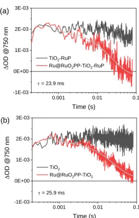
Figure 6. Transient absorption kinetics at 750 nm measured by laser
flash photolysis of thin films in N2-purged aqueous solutions containing
0.2 M TEOA at pH 7: (a) excitation at 532 nm of Ru@RuO2PP-TiO2-RuP
and TiO2-RuP, (b) excitation at 355 nm of Ru@RuO2PP-TiO2 and TiO2. Due to the irreversible nature of the TEOA oxidation process (eq 5), RuP+ reduction by the sacrificial donor leads to
accumulation of electrons in the TiO2 conduction band (eq
4,5). The fate of these electrons was followed by transient absorption spectroscopy from the featuring absorption in the red portion of the visible spectrum.27 Dye excitation at 532 nm
in TiO2-RuP in the presence of TEOA produces a permanent
transient absorption at 750 nm attributable to long-lived electrons in the TiO2 conduction band. This transient signal
remains indeed constant within the time-window of the experiment (Figure 6a, black trace). The same transient absorption is still present upon 532-nm excitation of the
Ru@RuO2PP-TiO2-RuP system in 0.2 M TEOA. However, this is
observed to decay to the baseline within ca. 100 ms (Figure 6a, red trace). This evidence can be attributed to the reduction of the Ru@RuO2PP catalyst by electrons in the TiO2 conduction
band (eq 6).
Ru@RuO2PP -TiO2(e−)-RuP
Ru@RuO2PP(e−)-TiO2-RuP (6)
Interestingly, comparable results are obtained in the absence of the RuP chromophore upon band-gap excitation at 355 nm
of the TiO2 semiconductor in the Ru@RuO2PP-TiO2
10-5 10-4 10-3 10-2 10-1 -0.06 -0.04 -0.02 0.00 D OD @450 nm Time (s) TiO2-RuP
TiO2-RuP / TEOA
0.001 0.01 0.1 -1E-03 0E+00 1E-03 2E-03 3E-03 (a) D OD @750 nm Time (s) TiO2-RuP
Ru@RuO2PP-TiO2-RuP = 23.9 ms 0.001 0.01 0.1 -1E-03 0E+00 1E-03 2E-03 3E-03 D OD @750 nm Time (s) TiO2 Ru@RuO2PP-TiO2 = 25.9 ms (b)
photocatalyst (Figure 6b), thus confirming the mechanistic assignment. A time-constant of = 25 ms can be estimated for the electron transfer from the TiO2 conduction band to the
Ru@RuO2PP nanoparticles. This value is considerably larger
than the one observed for the electron transfer from TiO2 to
two different molecular catalysts, namely a cobaloxime and a nickel(II) bis(diphosphine) complex,[18,28] suggesting a greater
inertness of the nanoparticulate material towards electron transfer with respect to molecular species. Furthermore, under continuous irradiation and concomitant electron accumulation within the catalytic unit the Fermi level of the metal nanoparticle is expected to up-shift.29 Accordingly, before
hydrogen elimination, electron transfer from the TiO2
conduction band to Ru@RuO2PP is expected to become
progressively less favorable on thermodynamic grounds and, as a consequence, kinetically slower. Taken together, considering the sequence of photo-triggered electron transfer processes previously discussed, these results unavoidably point towards the identification of the electron accumulation within the catalytic Ru@RuO2PP as the rate-determining step
in light-driven hydrogen evolution by the Ru@RuO2PP-TiO2 -RuP/TEOA system. The whole series of electron transfer
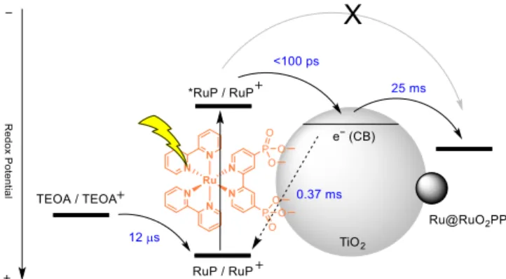
events is summarized in Figure 7.
Experimental
Materials and methods
4-phenylpyridine ligand and titanium dioxide P-25
anatase/rutile (TiO2) were purchased from Sigma Aldrich and
dried through vacuum/Ar cycles before their use. 0.2 M MilliQ aqueous solution of triethanolamine (Sigma Aldrich) was adjusted to pH 7 by the addition of HCl. The organometallic precursor [Ru(cod)(cot)] was commercially obtained from
Nanomeps. All solvents (Scharlab) were distilled over
Na/benzophenone (THF) or CaH2 (hexane) and degassed by
freeze-pump-thaw cycles. H2 and Ar were purchased from
Alphagaz. The synthesis of the nanoparticles was performed
under Ar inert atmosphere using Schlenk line techniques or a
glovebox (MBraun Unilab Worskstation 9550). The
photosensitizers [Ru(bpy)3](ClO4)2 and [Ru(bpy)2
(4,4’-(PO3H2)2(bpy)]Cl2 (RuP) were synthesized from procedures
previously described in the literature.[30–32]
2-Phenyl-4-(1-naphthyl)quinolinium triflate (QuPh+-NA) was synthesized
following a reported method.[33]
Figure 7. Schematic representation of the processes and kinetics of the
electron transfer events occurring upon irradiation of the
Ru@RuO2PP-TiO2-RuP/TEOA system.
Synthesis of supported Ru NPs onto TiO2 (Ru@RuO2PP-TiO2).
4-phenylpyridine-capped Ru nanoparticles (RuPP NPs) were prepared following a previous report12 by exposing under
hydrogen atmosphere (3 bar) a mixture of 150 mg (0.476 mmol) of [Ru(cod)(cot)] and 15 mg (0.095 mmol) of 4-phenylpyridine (PP) in dried and degassed THF in a Fischer Porter bottle for 16 h. One drop of the resulting colloidal solution was deposited onto a carbon covered copper grid for TEM characterization (mean diameter = 1.4 ± 0.3 nm). 12.8 mL or 64 mL of the colloidal black solution was then added under Ar onto 200 mg of TiO2 placed in two independent Schlenk
flasks and the mixtures were stirred for 4 days in the dark. The solvent was filtered off and the materials were washed with hexane (10 mL, 3 times) by cannula to obtain RuPP(2%)-TiO2 or
RuPP(10%)-TiO2 as grey solids. The obtained RuPP(2%)-TiO2
nanomaterial was placed into an Ar-filled screw cap vial and gradually exposed to air by slow oxygen diffusion at r.t. (20
days), yielding the corresponding Ru@RuO2PP-TiO2
nanohybrid. ICP-OES characterization of Ru@RuO2PP-TiO2
indicated a ruthenium content of 1.6 Ru wt.%.
Synthesis of supported RuPP NPs onto ZrO2 (Ru@RuO2PP-ZrO2).
Following the same procedure described above for the preparation of Ru@RuO2PP-TiO2, the addition of 2.55 mL of
the RuPP colloidal solution onto 40 mg of ZrO2 yields
Ru@RuO2PP-ZrO2 after slow surface-oxidation. ICP-OES: 1.6
Ru wt.%.
Synthesis of Ru@RuO2PP-TiO2-RuP. 4 mg of Ru@RuO2PP-TiO2
and 4 mL of (MilliQ) water were added to a vial containing a stir bar. The solid was sonicated for 5 min until total dispersion of the material. Then, 80 mL of an aqueous solution of RuP (5 mM) were added to the dispersion and the resulting suspension was stirred for 15 min. The solid was isolated by centrifugation (10 min, 2000 rpm) and washed 3 times with water. ICP characterization of Ru@RuO2PP-TiO2-RuP indicated
a ruthenium content of 1.6 wt.% (ICP-OES) and phosphorus content of 0.07 wt.% (ICP-MS).
Characterization
Transmission Electron Microsopy (TEM), High-Resolution Electron Microscopy (HRTEM), Energy-dispersive X-ray spectroscopy (EDX), High-Angle Annular Dark-Field Scanning Transmission Electron Microscopy (HAADF-STEM) and electron diffraction analysis were performed either in a JEOL 1400 microscope operating at 100kV at the “Servei de Microscopia Electronica” of the UAB or in a JEOL JEM 1011 microscope operating at 100kV with a resolution point of 0.45 nm or in a JEOL JEM-ARM 200F microscope working at 200kV with a resolution point lower of 0.19 nm at the “Centre de Microcaracterisation Raymond Castaing” in UMS-CNRS 3623.
ARTICLE Journal Name
8 | J. Name., 2012, 00, 1-3 This journal is © The Royal Society of Chemistry 20xx
Samples were prepared by deposition of some drops of dispersed material in a solvent onto a carbon covered copper grid. Micrographs were treated with ImageJ to obtain the statistical size distribution of the nanoparticles, assuming that they were spherical. NP sizes are quoted as the mean diameter ± the standard deviation. Inductive-Coupled Plasma (ICP-OES and ICP-MS) measurements were performed at the “Servei d'Analisi Quimica” (SAQ) in the UAB, on an Optima 4300DV Perkin-Elmer system. Solid samples were prepared by digesting 1 mg of the RuPPNPs-TiO2 with aqua regia under
microwave conditions followed by a dilution of the mixture with HCl 1 % (v/v). The samples were microfiltered (0.45 µm) prior to injection to eliminate white colloidal TiO2. X-ray
Photoelectron Spectroscopy (XPS) measurements were performed at the Catalan Institute of Nanoscience and Nanotechnology (ICN2) in Barcelona with a Phoibos 150 analyzer (SPECS GmbH, Berlin, Germany) in ultra-high vacuum
conditions (base pressure 5 × 10⁻¹⁰ mbar) with a
monochromatic aluminium Kalpha X-ray 456 source (1486.74 eV). The energy resolution was measured by the FWHM of the Ag 3d5/2 peak which for a sputtered silver foil was 0.62 eV.
Photocatalytic experiments
Hydrogen evolved was measured by using a Clark hydrogen
electrode (Unisense H2-NP-9463). The photocatalytic
hydrogen evolution reaction was performed in a 6 mL glass cell thermostated at 25 °C, containing 4 mL of 0.2 M TEOA as SED in which the photocatalyst was dispersed in the dark in an ultrasounds bath for 5 min. The cell was sealed with a septum and grease and the Clark electrode tip was introduced at the headspace of the cell (Figure S5). The solution was degassed with Ar bubbling for at least 10 min until stabilization of the signal. A concentrated water solution of the photosensitizer was injected. A flat signal was recorded for at least 2 min. Then, the cell was irradiated with a solar simulator (Abet 10500) containing a Xe lamp placed at exactly 1 sun (100 mW/cm2) distance. After recording the hydrogen evolution,
the cell was degassed by Ar bubbling and a calibration was
performed by injecting known volumes of H2 (usually 50, 100,
150, 200, 250, 300 and 400 μL, Figure S13) with a Hamilton syringe for gases.
Photophysical experiments
Time-resolved emission and absorption measurements were performed with a custom laser spectrometer comprised of a Continuum Surelite II Nd:YAG laser (FWHM 6 – 8 ns) with frequency doubled (532 nm) or tripled (355 nm) option, an Applied Photophysics xenon light source including a mod. 720 150W lamp housing, a mod. 620 power-controlled lamp supply and a mod. 03 102 arc lamp pulser. Laser excitation was provided at 90° with respect to the white light probe beam. Light emitted or transmitted by the sample was focused onto the entrance slit of a 300 mm focal length Acton SpectraPro 2300i triple grating, flat field, and double exit monochromator equipped with a photomultiplier detector (Hamamatsu R3896). Signals from the photomultiplier were processed by
means of a TeledyneLeCroy 604Zi (400 MHz, 20 GS/s) digital oscilloscope. The excitation pulse (either of 532 or 355 nm wavelength) was defocused using a diverging lens and set to an average energy of ~5 mJ/pulse using a combination of neutral density filters (Edmund Optics). Measurements were carried out at pH 7 in the presence of either 0.2 M TEOA or 0.1 M Na2SO4, the solutions were purged with nitrogen for 20
minutes before each experiment. TiO2 and ZrO2 thin films were
prepared by doctor-blading of TiO2 or ZrO2 paste onto
FTO-covered glasses (20 cm× 20 cm, TEC 8, 8 /cm, purchased from Pilkington) followed by calcination at 500°C for 30 min. An active surface area of 1.5 cm2 was achieved. The TiO2 paste
was commercial (18NR-T, GreatCell-Solar), while the ZrO2
paste was prepared according to the literature.34 Adsorption of
RuP onto TiO2 or ZrO2 thin films was performed by soaking
overnight the electrode into a 0.1 mM RuP solution in ethanol providing an absorbance of ~0.6 at the maximum of the MLCT
transition. Deposition of Ru@RuO2PP was performed by
dispersion of the nanomaterial in a THF solution (concentration approximately 2-3 mg/mL) followed by spin-coating (3 steps, each of 20 seconds at 2000 rpm). In the
three-component sample (Ru@RuO2PP-TiO2-RuP) deposition
of Ru@RuO2PP was made prior to soaking into the RuP
solution.
Conclusions
Summarizing, a ternary hybrid nanomaterial, Ru@RuO2
PP-TiO2-RuP, has been prepared through a synthetic protocol
comprising the organometallic synthesis of ruthenium nanoparticles stabilized by the 4-phenylpyridine ligand (RuPP), the deposition of the RuPP NPs onto TiO2 by impregnation of
the support, and the sensitization of the latter with a visible-light photoabsorber bearing phosphonic acid anchors (RuP).
When combined with TEOA as SED, the Ru@RuO2PP-TiO2-RuP
nanomaterial is able to promote efficient visible-light-driven HER photocatalysis for more than 100 h, yielding TON and TOF values over 480 molH2 · molRu-1 and 21.5 molH2 · h-1 · molRu-1,
respectively. Photophysical investigation by means of time-resolved spectroscopic techniques provided a proper description of the photoinduced dynamics within the hybrid photocatalytic system and pointed towards the identification of the electron accumulation within the Ru@RuO2PP catalyst
as the rate-limiting step in the photocatalysis. The combined photocatalytic and photophysical analysis allowed identifying the double key role of TiO2 in this HER photocatalytic system.
First, TiO2 acts as an efficient dispersing agent for the
nanoparticulate catalyst (Ru@RuO2PP) under aqueous
conditions, thus preventing its fast coagulation and consequent reduction of the accessible active sites. Second, it enables the electronic communication between the catalyst
(Ru@RuO2PP) and the anchored molecular photoabsorber
(RuP) under visible-light irradiation, acting as a competent (and necessary) electron-relay. Thus, the double role of TiO2 as
both support and electron-mediator allows to attain, to our knowledge for the first time, efficient visible-light-driven HER
photocatalysis combining a Ru-based photocatalyst and a molecular photoabsorber.
Conflicts of interest
There are no conflicts to declare.
Acknowledgements
This work was financially supported by the MINECO/FEDER project CTQ2015-64261-R, the CNRS and the University Paul Sabatier – Toulouse. M.N. acknowledges the University of Ferrara (FAR2019) for funding. RBG acknowledges Conselho Nacional de Desenvolvimento Científico e Tecnológico for the studentship (No. 142440/2015-9), to Fundo de Apoio ao Ensino, à Pesquisa e à Extensão – Universidade Estadual de Campinas (FAEPEX-UNICAMP), and to Prof. Dr. André Luiz Barboza Formiga. J.G.-A. acknowledges Serra Húnter Program. The authors acknowledge Guillaume Sauthier for XPS analysis.
Notes and references
1 N. S. Lewis, Science, 2016, 351, aad1920–aad1920.
2 A. González-Garay, M. S. Frei, A. Al-Qahtani, C. Mondelli, G. Guillén-Gosálbez and J. Pérez-Ramírez, Energy Environ. Sci., 2019, 12, 3425–3436.
3 J. R. McKone, N. S. Lewis and H. B. Gray, Chem. Mater.,
2014, 26, 407–414.
4 K. Takijiri, K. Morita, T. Nakazono, K. Sakai and H. Ozawa,
Chem. Commun., 2017, 53, 3042–3045.
5 M. Li, K. Duanmu, C. Wan, T. Cheng, L. Zhang, S. Dai, W. Chen, Z. Zhao, P. Li, H. Fei, Y. Zhu, R. Yu, J. Luo, K. Zang, Z. Lin, M. Ding, J. Huang, H. Sun, J. Guo, X. Pan, W. A. Goddard, P. Sautet, Y. Huang and X. Duan, Nat. Catal., 2019, 2, 495–503.
6 C. C. L. McCrory, S. Jung, I. M. Ferrer, S. M. Chatman, J. C. Peters and T. F. Jaramillo, J. Am. Chem. Soc., 2015, 137, 4347–4357.
7 J. Creus, J. De Tovar, N. Romero, J. García-Antón, K. Philippot, R. Bofill and X. Sala, ChemSusChem, 2019, 12, 2493–2514.
8 J. Yu, Q. He, G. Yang, W. Zhou, Z. Shao and M. Ni, ACS
Catal., 2019, 9, 9973–10011.
9 S. Han, Q. Yun, S. Tu, L. Zhu, W. Cao and Q. Lu, J. Mater.
Chem. A, 2019, 7, 24691–24714.
10 C. Amiens, D. Ciuculescu-Pradines and K. Philippot, Coord.
Chem. Rev., 2016, 308, 409–432.
11 R. Matheu, I. A. Moreno-Hernandez, X. Sala, H. B. Gray, B. S. Brunschwig, A. Llobet and N. S. Lewis, J. Am. Chem. Soc., 2017, 139, 11345–11348.
12 J. Creus, S. Drouet, S. Suriñach, P. Lecante, V. Collière, R. Poteau, K. Philippot, J. García-Antón and X. Sala, ACS Catal., 2018, 8, 11094–11102.
13 Y. Yamada, S. Shikano and S. Fukuzumi, J. Phys. Chem. C, 2013, 117, 13143–13152.
14 S. Fukuzumi and Y. Yamada, J. Mater. Chem., 2012, 22,
24284–24296.
15 Y. Yamada, T. Miyahigashi, H. Kotani, K. Ohkubo and S.
Fukuzumi, J. Am. Chem. Soc., 2011, 133, 16136–16145.
16 Y. Yamada, T. Miyahigashi, K. Ohkubo and S. Fukuzumi,
Phys. Chem. Chem. Phys., 2012, 14, 10564–10571.
17 Y. Pellegrin and F. Odobel, Comptes Rendus Chim., 2017,
20, 283–295.
18 F. Lakadamyali, A. Reynal, M. Kato, J. R. Durrant and E. Reisner, Chem. - A Eur. J., 2012, 18, 15464–15475.
19 M. A. Melo, Z. Wu, B. A. Nail, A. T. De Denko, A. F. Nogueira and F. E. Osterloh, Nano Lett., 2018, 18, 805–810.
20 W. Kim, E. Edri and H. Frei, Acc. Chem. Res., 2016, 49, 1634–1645.
21 E. B. And and W. Choi, J. Phys. Chem. B, 2006, 110, 14792–
14799.
22 K. Hara, K. Miyamoto, Y. Abe and M. Yanagida, J. Phys.
Chem. B, 2005, 109, 23776–23778.
23 D. F. Zigler, Z. A. Morseth, L. Wang, D. L. Ashford, M. K. Brennaman, E. M. Grumstrup, E. C. Brigham, M. K. Gish, R. J. Dillon, L. Alibabaei, G. J. Meyer, T. J. Meyer and J. M. Papanikolas, J. Am. Chem. Soc., 2016, 138, 4426–4438. 24 M. Natali, M. Orlandi, S. Berardi, S. Campagna, M. Bonchio,
A. Sartorel and F. Scandola, Inorg. Chem., 2012, 51, 7324– 7331.
25 R. R. Knauf, M. K. Brennaman, L. Alibabaei, M. R. Norris and J. L. Dempsey, J. Phys. Chem. C, 2013, 117, 25259–25268. 26 T. A. Heimer, E. J. Heilweil, C. A. Bignozzi and G. J. Meyer, J.
Phys. Chem. A, 2000, 104, 4256–4262.
27 A. Kafizas, X. Wang, S. R. Pendlebury, P. Barnes, M. Ling, C. Sotelo-Vazquez, R. Quesada-Cabrera, C. Li, I. P. Parkin and J. R. Durrant, J. Phys. Chem. A, 2016, 120, 715–723. 28 M. A. Gross, A. Reynal, J. R. Durrant and E. Reisner, J. Am.
Chem. Soc., 2014, 136, 356–366.
29 W. Bi, L. Zhang, Z. Sun, X. Li, T. Jin, X. Wu, Q. Zhang, Y. Luo, C. Wu and Y. Xie, ACS Catal., 2016, 6, 4253–4257. 30 M. R. Norris, J. J. Concepcion, C. R. K. Glasson, Z. Fang, A.
M. Lapides, D. L. Ashford, J. L. Templeton and T. J. Meyer,
Inorg. Chem., 2013, 52, 12492–12501.
31 D. L. Ashford, M. K. Brennaman, R. J. Brown, S. Keinan, J. J. Concepcion, J. M. Papanikolas, J. L. Templeton and T. J. Meyer, Inorg. Chem., 2015, 54, 460–469.
32 P. Jansa, O. Baszczyňski, E. Procházková, M. Dračínský and Z. Janeba, Green Chem., 2012, 14, 2282–2288.
33 H. Kotani, K. Ohkubo and S. Fukuzumi, Faraday Discuss.,
2012, 155, 89–102.
34 A. Orbelli Biroli, F. Tessore, M. Pizzotti, C. Biaggi, R. Ugo, S. Caramori, A. Aliprandi, C. A. Bignozzi, F. De Angelis, G. Giorgi, E. Licandro and E. Longhi, J. Phys. Chem. C, 2011,

![Figure 3. Photocatalytic hydrogen evolution profile (left) and hydrogen evolution rate per 2h (right) for Ru@RuO 2 PP-TiO 2 (4 mg) + [RuP] = 0.1 mM (green) and Ru@RuO 2 PP-TiO 2 -RuP (red) under visible-light irradiation in a 4 mL TE](https://thumb-eu.123doks.com/thumbv2/123doknet/13730521.436282/6.892.65.431.110.253/figure-photocatalytic-hydrogen-evolution-profile-hydrogen-evolution-irradiation.webp)