HAL Id: hal-00330118
https://hal.archives-ouvertes.fr/hal-00330118
Submitted on 8 Mar 2007
HAL is a multi-disciplinary open access
archive for the deposit and dissemination of
sci-entific research documents, whether they are
pub-lished or not. The documents may come from
teaching and research institutions in France or
abroad, or from public or private research centers.
L’archive ouverte pluridisciplinaire HAL, est
destinée au dépôt et à la diffusion de documents
scientifiques de niveau recherche, publiés ou non,
émanant des établissements d’enseignement et de
recherche français ou étrangers, des laboratoires
publics ou privés.
orbit missions
N. P. Bannister, E. J. Bunce, S. W. H. Cowley, R. Fairbend, G. W. Fraser, F.
J. Hamilton, J. S. Lapington, J. E. Lees, M. Lester, S. E. Milan, et al.
To cite this version:
N. P. Bannister, E. J. Bunce, S. W. H. Cowley, R. Fairbend, G. W. Fraser, et al.. A Wide Field
Auroral Imager (WFAI) for low Earth orbit missions. Annales Geophysicae, European Geosciences
Union, 2007, 25 (2), pp.519-532. �hal-00330118�
© European Geosciences Union 2007
Geophysicae
A Wide Field Auroral Imager (WFAI) for low Earth orbit missions
N. P. Bannister1, E. J. Bunce1, S. W. H. Cowley1, R. Fairbend2, G. W. Fraser1, F. J. Hamilton1, J. S. Lapington1, J. E. Lees1, M. Lester1, S. E. Milan1, J. F. Pearson1, G. J. Price1, and R. Willingale1
1Department of Physics & Astronomy, University of Leicester, University Road, Leicester, LE1 7RH, UK 2Photonis SAS, Avenue Roger Roncier, Brive, 19410 Cedex, France
Received: 6 January 2006 – Revised: 12 December 2006 – Accepted: 22 January 2007 – Published: 8 March 2007
Abstract. A comprehensive understanding of the solar wind
interaction with Earth’s coupled magnetosphere-ionosphere system requires an ability to observe the charged particle en-vironment and auroral activity from the same platform, gen-erating particle and photon image data which are matched in time and location. While unambiguous identification of the particles giving rise to the aurora requires a Low Earth Orbit satellite, obtaining adequate spatial coverage of auro-rae with the relatively limited field of view of current space bourne auroral imaging systems requires much higher orbits. A goal for future satellite missions, therefore, is the develop-ment of compact, wide field-of-view optics permitting high spatial and temporal resolution ultraviolet imaging of the au-rora from small spacecraft in low polar orbit. Microchannel plate optics offer a method of achieving the required perfor-mance. We describe a new, compact instrument design which can observe a wide field-of-view with the required spatial resolution. We report the focusing of 121.6 nm radiation us-ing a spherically-slumped, square-pore microchannel plate with a focal length of 32 mm and an F number of 0.7. Mea-surements are compared with detailed ray-trace simulations of imaging performance. The angular resolution is 2.7±0.2◦ for the prototype, corresponding to a footprint ∼33 km in di-ameter for an aurora altitude of 110 km and a spacecraft alti-tude of 800 km. In preliminary analysis, a more recent optic has demonstrated a full width at half maximum of 5.0±0.3 arcminutes, corresponding to a footprint of ∼1 km from the same spacecraft altitude. We further report the imaging prop-erties of a convex microchannel plate detector with planar resistive anode readout; this detector, whose active surface has a radius of curvature of only 100 mm, is shown to meet the spatial resolution and sensitivity requirements of the new wide field auroral imager (WFAI).
Keywords. Magnetospheric physics (Instruments and
tech-niques) – Radio science (Remote sensing)
Correspondence to: N. P. Bannister
(npb@star.le.ac.uk)
1 Introduction
Observations of the aurora (representing magnetic field-mapped images of magnetospheric plasma populations), in combination with ionospheric flow monitoring from the ground and space, provide unique information on magneto-spheric dynamics and are thus a powerful diagnostic for the way in which the solar wind influences auroral activity (Doe et al., 1997). Beginning with the Dynamics Explorer 1 satel-lite (Frank et al., 1981), several missions have obtained ultra-violet images of the auroral oval (as opposed to non-imaging measurements made on earlier missions). These observations can be combined with measurements from particle and field detectors and with ground-based radar data to derive a com-prehensive understanding of the solar wind interaction with Earth’s coupled magnetosphere-ionosphere system (e.g. Mi-lan et al., 2003).
Auroral imaging missions typically occupy highly ellip-tical, high-altitude near-polar orbits to ensure efficient cov-erage of high latitudes. For example, the IMAGE space-craft had an initial apogee of ∼45 000 km over the Northern Hemisphere (Mende et al., 2000), and a perigee of 1000 km. However, in-situ monitoring of the charged particles re-sponsible for the production of auroral displays requires in-strumentation in low Earth orbit (LEO); for example, the Fast Auroral Snapshot Explorer (FAST) was launched into a 351×4175 km polar orbit (Carlson et al., 1998), while satellites of the Defense Meteorological Satellite Program (DMSP) are in 830 km circular near-polar orbits (see for ex-ample Rich et al., 1985).
The different orbits of particle detector and auroral imager spacecraft preclude complete correlation of data. Further-more, current auroral imagers are unable to provide a simul-taneous match to the coverage and spatial resolution of mod-ern ground-based radar systems such as the Super Dual Au-roral Radar Network “SuperDARN” (Greenwald et al., 1995) from LEO. Wide-field coverage requires the use of high al-titudes, while high spatial resolution can only be achieved
Fig. 1. Percentage coverage of a hemisphere of the Earth versus orbital radius for FOV values between 1◦ and 20◦. The dashed line indicates a coverage of 9.4%, equivalent to the auroral oval (Ruohoniemi and Baker, 1998). Orbital radius is expressed in Earth radii, measured from the centre of the Earth.
using instruments at lower altitudes. Imaging the entire auro-ral oval requires a field of view (FOV) of ∼136◦at an altitude of 800 km above the pole (Ruohoniemi and Baker, 1998), and conventional optics fall significantly short of these re-quirements. For example, the Wideband Imaging Camera (WIC) onboard IMAGE has a 17◦×17◦ FOV and a spatial resolution of 52×52 km per pixel at apogee, or 1.2×1.2 km at perigee (Mende et al., 2000; Frey et al., 2001), while the ultraviolet imager on Freja (with a 600×1700 km orbit) had a FOV of 22.4◦×30◦and a spatial resolution of 5 km at apogee (Murphree et al., 1994). Figure 1 shows the coverage of the accessible hemisphere of the Earth as a function of geocen-tric radial distance for FOV values between 1◦and 20◦. It is clear that acceptable auroral coverage is only achievable, us-ing conventional optics, from geocentric orbital radii greater than about ∼3.5 RE, at the expense of spatial resolution (and feasibility, given that the majority of mission opportunities are likely to be in LEO).
The goal of synoptic auroral imaging requires an innova-tive step in optical design. In this paper we describe a novel design for a wide FOV far ultraviolet (FUV) auroral imager based on microchannel plate (MCP) optics technology. The Wide Field Auroral Imager (WFAI), shown in Fig. 2, consists of several subsystems. Microchannel plate (MCP) optics fo-cus a wide field, high resolution image of the aurora onto a detector consisting of a curved (“slumped”) MCP electron multiplier and resistive anode readout, which records the po-sition and arrival time of photons, allowing the scanning mo-tion of the orbital platform to be removed from the image. Although the detector has negligible energy resolution, the use of appropriate filters allows quantitative observations in particular wavelength regions of interest. In the following
Fig. 2. WFAI module schematic. Note that planar windows and filters may be substituted for the curved elements shown here. Ap-proximate scale indicated.
sections we discuss the function and principal design fea-tures of each subsystem. Section 2 describes the main re-quirements of an auroral imaging instrument, and in Sect. 3 we outline the performance characteristics of microchannel plate optics including an estimation of count rates expected for typical auroral observations. In Sect. 4 we describe the performance of a prototype MCP optic of 3 cm focal length, and in Sect. 5 we consider an MCP detector of pronounced convex curvature which is suitable for use in the instrument. Section 6 contains a brief consideration of module and in-strument design, followed in Sect. 7 by a discussion of the results from the current programme and prospects for future instrument development. The next stages of our WFAI de-velopment programme are summarised in Sect. 8.
2 Instrument requirements
2.1 Science requirements
The instrument design drivers are given in Table 1. Optical design and spacecraft orbital parameters should combine to make possible the instantaneous viewing of most of the auro-ral oval, while spatial resolution must be sufficient to resolve structure on scales better than 25 km, providing adequate cor-relation with ionospheric flow measurements. Bright auro-ral features can exhibit horizontal velocities of up to seveauro-ral km s−1; temporal resolution is therefore also an important factor. Conventional detectors, such as the intensified CCDs of the VIS instrument on Polar (Frank et al., 1995) are inte-grating devices, and thus provide no information about pho-ton arrival time within a given frame time. In such a detector, the maximum integration time before blurring occurs is given by the ratio of instrument spatial resolution to spacecraft ve-locity, which, in polar LEO, is ∼7.5 km s−1. For a resolution
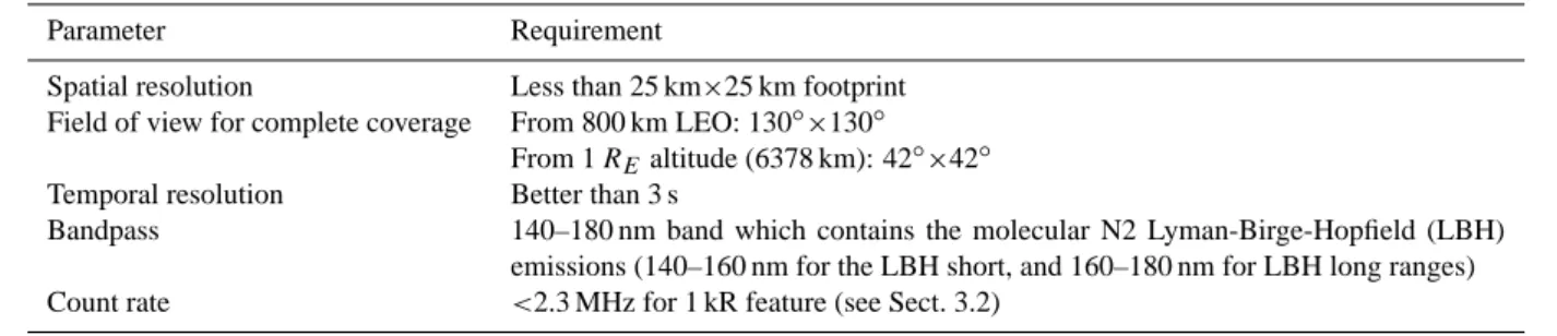
Table 1. Performance requirements of a wide field FUV auroral imager in polar LEO.
Parameter Requirement
Spatial resolution Less than 25 km×25 km footprint Field of view for complete coverage From 800 km LEO: 130◦×130◦
From 1 REaltitude (6378 km): 42◦×42◦
Temporal resolution Better than 3 s
Bandpass 140–180 nm band which contains the molecular N2 Lyman-Birge-Hopfield (LBH) emissions (140–160 nm for the LBH short, and 160–180 nm for LBH long ranges) Count rate <2.3 MHz for 1 kR feature (see Sect. 3.2)
of 25 km, the maximum integration time is therefore ∼3 s. In contrast, with the photon counting MCP detector described in Sect. 4 the arrival times of individual photons can be recorded with a precision which is better than 1 ms (e.g. Siegmund et al., 1997). Since the velocity vector of the spacecraft is well known, the instantaneous arrival position of the photon in the moving imager frame can be mapped back onto the Earth frame with an uncertainty given by the spacecraft velocity
Vsc multiplied by the instrument time resolution, τ , which in this case is less than 7.5 m. The effective limit on obser-vation time for a stationary auroral feature is determined by how long that feature stays in the field of view of the imager. The required angular resolution (1θ ) is determined from the minimum cell length (L) on the Earth’s surface for a given separation between spacecraft and object, h:
L = h tan (1θ) . (1)
The distance along a line of sight to the aurora (h) increases with the angle between the nadir and that line of sight. We can place limits on the angular resolution required by con-sidering the extreme case of imaging the entire auroral oval from a position above the pole. This requires a FOV of 136◦ and an angular resolution of 0.47◦ for a cell of 25 km from an altitude of 800 km, assuming the auroral emission occurs at 110 km altitude above the surface of the Earth. To image a 25 km auroral cell at nadir, the angular resolution required is 2.08◦. As we discuss below, these performance specifica-tions are achievable with MCP optics.
2.2 Bandpass filters
The primary goal of the WFAI is to provide high spatial and temporal resolution imaging in a global context (i.e. images of the entire auroral oval) at perigee in LEO. Although high spectral resolution is unnecessary to meet these goals, the addition of energy resolution increases the science which can be performed with the instrument. Since MCP detectors have negligible intrinsic energy resolution, adding this capability requires the introduction of filters to define specific band-passes.
It has been shown with previous imagers that the ability to determine the ratio of one wavelength band to another (for
instance between the “long” and “short” bands of the Lyman-Birge-Hopfield (LBH) N2lines) can provide information on
the depth of penetration of the particles giving rise to the au-rora (e.g. Torr et al., 1995). This in turn provides an estimate of the energy spectrum of the particles, allowing the parti-cle source region to be identified. To date, the most effective FUV filters for auroral imaging (in terms of their ability to provide narrow bandwidth and effective out-of-band block-ing) are those produced for the FUV imager on board the Polar Mission. These sophisticated filters, described by Zu-kic et al. (1993), allow the isolation of specific wavebands of interest. Narrowband filters designed for observation of OI lines have a bandwidth of <5 nm, and a peak transmittance of 23.9% and 38.3% for filters with central wavelengths of 130.4 and 135.0 nm, respectively, allowing quantitative mea-surements of the 130.4 and 135.6 nm lines of OI. Broadband filters for the FUV imager allow quantitative measurements of the LBH-s (140–160 nm) and LBH-l (160–180 nm) bands: one filter provides a bandpass centred at 150 nm with a band-width of 10 nm, serving the LBH-s region; the other, with a central wavelength of 170 nm and a bandwidth of 11 nm, is well matched to the LBH-l region. These highly selective filters allow the measurement of precipitating particle en-ergies and interaction altitudes. A well-established method of determining these parameters involves the comparison of two emission lines, one of which is absorbed by the oxy-gen Schumann-Runge absorption continuum, as a function of altitude (e.g. Germany et al., 1998). For example, more energetic electrons penetrate deeper into the atmosphere be-fore producing aurorae; photons emitted in the LBH-s are absorbed by O in the atmosphere, while photons in the LBH-l band are not. Hence the strength of the LBH-LBH-l emission can be used to indicate the power input to the system, while the ratio of the LBH-s to the LBH-l emission provides informa-tion on the altitude and energy of the auroral activity.
Although filters for the Polar-FUV imager are ideally matched to the diagnostic methods described above, they are reflection devices (multi-layer 5-stacks), used at a 45◦ angle of incidence, in order to produce these highly spe-cific wavebands. Reflection filters are incompatible with the very compact WFAI design, and are unsuitable for wide-field
Table 2. Columns 1–3: transmission properties for filters appropri-ate to the WFAI instrument, based on those flown on the DE-1 mis-sion. Columns are central wavelength, bandpass FWHM, and trans-mission at central wavelength. Columns 4 & 5: estimated count rate for dayside auroral observations in each band, for a bare glass and CsI photocathode-equipped detector respectively, for a single WFAI module with 45.8◦×45.8◦field of view.
λc(nm) 1λ (nm) Tc(%) Rglass(cts/s) RCsI(cts/s)
156.0 34 18 1.62×10⁶ 3.99×10⁷ 150.0 41 25 4.52×10⁶ 1.06×10⁸ 154.0 43 17 2.67×10⁶ 6.32×10⁷
applications, where the broad range of input angles leads to a broadening of the filter bandpass. Filters for the WFAI must be used in transmission, and must be compatible with the wide field and large focal plane of the imaging device. Zu-kic et al. (1993) review the development of filters for FUV applications, and find that previous designs used in transmis-sion resulted in low throughput, and provided wavebands too large for the selectivity required to perform the diagnostics described above. In addition, some filters (e.g. those based on the Fabry-P´erot design) suffer from pass windows at longer wavelengths. This is particularly undesirable in the context of the WFAI, where global imaging of auroral emission re-quires observations in both the night-time and daylit hemi-spheres; in the latter case, long wavelength leakage will ad-mit significant quantities of visible photons which will mask the FUV emission.
The lack of narrow bandwidth transmission filters with comprehensive out-of-band blocking characteristics pre-cludes certain studies, such as measurement of precipitating particle energies and interaction altitudes described above. However, transmission devices are available which provide useful wavelength selectivity and which have a proven space heritage. Frank et al. (1981) describe filters used on the Dynamics Explorer Mission. These devices comprise both narrow-band interference filters and BaF2, CaF2and MgF2
windows. Aluminium flashing is applied to the windows to suppress long wavelength transmission, allowing auroral ob-servations in the sunlit ionosphere. Table 2 includes specifi-cations for three DE-1 filters which are of particular interest in the context of the WFAI instrument, along with count rate estimates for each filter in the WFAI context (these estimates are discussed in Sect. 3.2). The design of these filters appears to be compatible with the requirements of the WFAI in that they are used in transmission, and can be produced in formats which are large enough to cover the WFAI focal plane.
The filters cover the LBH band, and are sufficiently opaque to Lyman α wavelengths so that, when combined with a window material such as CaF2, auroral emissions in
the LBH band can be imaged in both the dark and sunlit
iono-spheres. By restricting the WFAI to a single, broad band-pass covering the LBH emissions, the ability to measure the precipitating electron energies and distributions from direct measurements of the long- and short- LBH measurements is lost. However, quantitative measurements of electron impact excitation of N2in dark and sunlit ionospheres becomes
pos-sible, and missions such as DE-1 and IMAGE have shown that such broadband measurements can produce valuable sci-ence (see e.g. Rairden et al., 1986; Frey et al., 2003).
3 Microchannel plate optics
3.1 Overview
To determine whether the proposed instrument can meet the scientific goals, we consider previous MCP optic results from Leicester and elsewhere, and the auroral imager performance which could be obtained with these MCPs. We describe the results of Monte Carlo ray trace simulations used to specify the MCP geometry (radius of curvature, channel width etc) for optimum FUV imaging in terms of effective area and an-gular resolution. We then estimate the sensitivity and maxi-mum count rate expected from an MCP-based auroral imager in LEO.
An MCP optic consists of a spherically curved glass plate containing a very large number of channels of square cross section, mutually aligned with good regularity. The plate cur-vature is not introduced by grinding methods (as employed for conventional telescope mirrors and lenses) but is pro-duced by bending or “slumping” the initially planar MCP onto a polished metal mandrel. This produces a different channel geometry to grinding: in the ground MCP, the pore axes are parallel, while in the slumped MCP the long axes of all the channels intersect at a distance RMCP(the MCP radius
of curvature) along the optical axis. A metallic layer (e.g. Ni) is deposited on the channel walls to enhance the reflectivity of the optic at X-ray energies. Recent studies have investi-gated alternative coating materials (e.g. Ir, Ru, Pt) (Nussey, 2005), and work on identifying the optimum coating for use in a wide field auroral imager (WFAI) such as that described here is ongoing.
Parallel beams of radiation are focused to a point by or-thogonal reflections from the walls of the channels. The fo-cal length of an MCP optic is f =RMCP/2 (for a source at
infinity) and the point spread function (PSF) is cruciform in nature (Fraser et al., 1993a), consisting of a central focus pro-duced by odd numbers of reflections off orthogonal faces, ac-companied by intersecting line foci which arise from single reflections. MCP optics have no “preferred axis”, permit-ting much larger fields of view than those possible with con-ventional optical designs. MCP optics are the key technol-ogy for the Lobster imaging all-sky X-ray telescope (Fraser et al., 2002); here, they allow us to realise a compact, low mass instrument which meets the requirements of Table 1. In
Table 3. MCP optic parameters considered in X-ray studies to date and in the present work.
Parameter Demonstrated values Channel side length (D) 8.5–200 µm Channel aspect ratio (L/D) 50:1–500 :1 Format up to 54×54 mm2 Slump radius (RMCP) 0.07–1.0 m
Channel surface roughness 1.1 nm rms
Angular resolution 7 arcminutes FHWM Metallisation for enhanced reflectivity Ni, Ir, or Ru
Table 3 we summarise the range of MCP parameters demon-strated in previous laboratory studies at the University of Le-icester Space Research Centre (see, for example, Brunton et al., 1997, 1999; Fraser et al., 1994). The best angular reso-lution demonstrated in previous X-ray work (7′full width at half maximum, or FWHM) is a factor of four better than the value required to provide a match to radar data, from LEO (see Sect. 2).
The bandpass over which a given MCP optic can focus is determined by its aspect ratio (channel length L divided by channel width, D). Fraser et al. (1993a) describe the focusing of parallel beams of 0.1–2 keV X-rays, while re-sults for hard X-ray focusing (50–65 keV) are presented by Price et al. (2002). The present paper is concerned with the performance of MCP optics in the FUV waveband de-fined by the bandpass filters discussed above. Since angu-lar resolution 1θ is an important consideration, the MCP channel size D must be chosen such that diffraction effects, which scale as λ/D, are negligible. For the D=84µm chan-nels of the prototype optic (Sect. 4), the diffraction contri-bution is only 4.9 arcsec FWHM at 121.6 nm, which is in-significant compared to (a) the intrinsic geometrical reso-lution D/f =5.8 arcminutes, and (b) the target resoreso-lution of 2.08◦for 25 km cells at nadir from 800 km altitude.
3.2 WFAI optic design and detector requirements
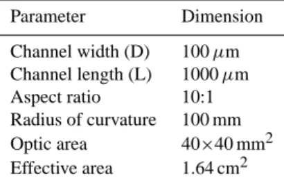
A Monte-Carlo ray tracing model (Brunton et al., 1997) has been used to establish the optimal design parameters in terms of maximising optic effective area. In the model, a square-pore MCP optic with slump radius RMCP=100 mm focuses
light onto a spherically slumped MCP detector of the same radius. Although the ideal detector radius of curvature is half that of the optic, slumping a microchannel plate electron multiplier to only 50 mm radius is likely to present significant manufacturing difficulty. Adopting the larger radius of cur-vature will increase the FWHM of the point spread function by approximately 20% at the extreme edge of the field. The results of this modelling are presented in Table 4. In this sec-tion we estimate the detector requirements of an instrument based on this ideal MCP optic, beginning with an estimation
Table 4. MCP optic properties adopted for the ray tracing study (the effective area is wavelength independent in the FUV band con-sidered here). Parameter Dimension Channel width (D) 100 µm Channel length (L) 1000 µm Aspect ratio 10:1 Radius of curvature 100 mm Optic area 40×40 mm2 Effective area 1.64 cm2
of the maximum count rate which can be sustained by the de-tector, followed by an estimation of the count rates expected for a typical auroral observation. The count rate generated in the instrument is dependent on the electron barrier, bandpass filter (these two roles being combined into a single element), and any QE-enhancing detector photocathode, as well as the optic itself. Filters and any photocathodes should be chosen such that the detected count rate does not exceed the count rate capacity of the detector when imaging a typical bright aurora.
The maximum achievable count rate in an MCP detector is limited by the charge replenishment time of the channels, which is related to the ratio of MCP output pulse current Ip to strip current Is(i.e. the MCP conductance current flowing in the high resistivity surface conducting glass of the MCP structure). These quantities can be expressed as
Ip= ¯GN, (2) and Is = V0 Rch , (3)
where ¯G is the average charge gain of the detector, N is the
count rate per channel, V0 is the bias voltage of the MCP
and Rchis the effective resistance of a single microchannel (Fraser et al., 1991). Fraser et al. (1993b) model the op-eration of MCP detectors at high count rates, and provide data for the variation in limiting pulse current to strip cur-rent ratio (Fig. 1 in that work), as a function of the num-ber of channels illuminated, for MCP detectors with chan-nel sizes similar to those proposed for the WFAI. In the case of the MCP detector discussed here, the 12.5 µm diameter channels are arranged in a hexagonal close pack structure with a pitch of 15 µm, and thus the channel number den-sity is approximately 5.1×10⁹m−2. The illuminated area of the detector has a diameter of 40 mm, so that there are ap-proximately 6.4×10⁶ illuminated channels. From Fig. 1 of Fraser et al. (1993b), the limiting ratio Ip/Is in this case is
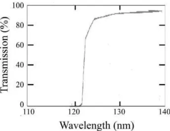
Fig. 3. Transmission curve for 0.5 mm thick CaF2filter. Data from
Laufer et al. (1965).
approximately 0.1. From Eqs. (2) and (3), the ratio Ip/Iscan be expressed as Ip Is = ¯ GN Rch V0 ≈ 0.1. (4)
We now make some conservative assumptions for the perfor-mance of the MCP to be used in the WFAI detector, adopting
V0=1500 V, ¯G=1 pC and Rmcp=40 M. Treating the MCP as
6.4×10⁶resistors in parallel, the resistance of an individual channel is Rch=2.6×10¹⁴. Then from Eq. (4), the limiting
count rate per channel is N =0.6 cts s−1. Hence, for full field illumination we find a maximum count rate of approximately 4×10⁶counts s−1can be sustained by the multiplier.
Auroral intensity (expressed in Rayleighs, where 1 Rayleigh corresponds to 106 photons s−1cm−2, emitting into 4π sr), is conventionally quoted as the intensity of the strongest emission line within the spectrum (the 130.5 nm OI line). However, in the case of the WFAI, it is the integrated intensity over the range of wavelengths defined by the band-pass filter, which is of interest. Torr et al. (1995) provide data on the spectrum of the aurora (Fig. 2.4.1b and Table 2.6.1 in that work), and find that in the 140–170 nm band, the inte-grated intensity of the aurora is typically between 600–1200 Rayleighs, with the dayglow emission being of a similar in-tensity; in addition, there are strong lines of OI at 130.4 and 135.6 nm which fall within the bandpass of the filters con-sidered here. We have estimated typical count rates which would be observed by an MCP optic-based auroral imager, assuming a total emission of 2400 Rayleighs in the observed waveband (dayglow and aurora), plus contributions from the OI lines at the maximum level quoted by Torr et al. (1995), i.e. 20 000 and 2000 Rayleighs at 130.4 nm and 135.6 nm, respectively. The count rate R in a detector with quantum
ef-ficiency (QE) Q at the focus of an MCP optic with effective area A in cm2is (based on Eq. (3), Torr et al., 1995),
R = 10 6
4π AtwtfQI, (5)
where is the solid angle subtended by the instrument field of view, tw, is the transmission of the window (used to seal the detector against electrons – see Sect. 6.2), tf, the trans-mission of the bandpass filter, and the brightness of the emis-sion integrated over the wavelength range of interest is I Rayleighs.
To estimate R we adopt the wavelength-independent optic effective area of 1.64 cm2determined from the Monte Carlo studies of a mechanically perfect optic with L:D=10:1 (see Table 4). We consider the response of the instrument for the three filters listed in Table 2, and in each case adopt the wavelength-dependent CaF2window transmission shown in
Fig. 3. We have considered the response of the instrument based on a detector with (a) bare glass MCPs, and (b) a con-figuration in which the input face of the front MCP has a CsI photocathode (KBr photocathodes suffer from a minimum in the secondary electron yield at 170 nm and are therefore not considered). Simons et al. (1987) provide information on the QE of bare glass and CsI photocathode-equipped MCPs as a function of wavelength in the FUV region, and we assume these data here (efficiencies at these wavelengths are low – e.g. at 160 nm, Qbare=0.05% and QCsI=4%). We find that
if the source fills the entire field of view of a single mod-ule of the design described in Sect. 6 (i.e. a modmod-ule consist-ing of 4 MCPs to generate a 45.8×45.8◦(0.622 steradian) field of view satisfying the requirements outlined in Table 1), the resulting count rates range from Rglass=1.62×10⁶counts s−1 for the first filter listed in Table 2, to a maximum of
RCsI=1.06×10⁸ counts s−1 in the case of the second filter.
These rates are upper limits since the auroral intensity will not be uniformly bright in the field of view. Count rates are approximately halved for observations of the night-side iono-sphere. The results are summarised in columns 4 and 5 of Table 2.
Detecting changes in the size of the “dim” region inside the auroral oval can give quantitative measurements of the magnetic reconnection rates at the dayside and in the mag-netotail. This diagnostic is discussed by Milan et al. (2003). From Fig. 2 in that work we assume a factor of 40 differ-ence between the brightest and faintest auroral emission to be imaged and hence the count rate for the dim region on the night-side, assuming a bare glass MCP and the first filter in Table 2, is Rglass=2×10⁴counts s−1. This compares to an in-trinsic noise level of 0.1 counts cm−2s−1for a typical MCP detector, i.e. <2 counts s−1for the sensitive area considered here.
While the processing of such large signals is not consid-ered in this paper, it is apparent that bare glass MCP elec-tron multipliers are capable of operation at the count rates
The 46 mm diameter test optic. The squares seen on the surfa
Fig. 4. The 46 mm diameter test optic. The squares seen on the surface are multifibre boundaries. The areas with more distinct dis-colouration contain more significant multifibre errors. The cruci-form feature visible slightly right of centre is produced by light re-flected from the channel walls.62 63 64 65 -20 -15 -10 -5 0 5 10 15 20 Traverse distance (mm) V er ti ca l d is p la ce m en t ( m m ) ± µ
Fig. 5. Profile of test optic as determined by Talysurf profilometer. Open circles and triangles show measurements of the profile in or-thogonal directions. Also shown (solid line) is the best fit circle to the profiles (radius 64.6 mm). The maximum deviation of the optic profile from the best fit is of order 190 µm.
expected, and in addition have the benefit of simplifying de-tector manufacture and handling procedures.
4 Performance of prototype MCP optics
We have evaluated the performance of a prototype optic, manufactured by Photonis SAS. The MCP (shown in Fig. 4) was produced for a study into slumping procedures, and is not optimised for the current work. In particular, the L/D value of 49:1 results in a lower effective area compared to the ideal L/D discussed in Sect. 3. The MCP prototype is specified in Table 5.
The geometrical figure was characterised by two orthogo-nal scans of a Talysurf profilometer, and is shown in Fig. 5.
Table 5. Prototype MCP parameters.
Parameter Value Outer diameter 46.0±0.5 mm Channel size D 84±2 µm Channel length L 4.2±0.1 mm Channel pitch P 103±2 µm Radius of curvature RMCP 64.6±0.2 mm Saggital depth 4.5±0.2 mm Theoretical open area fraction 0.66±0.04 Coating None
The MCP diameter was 46 mm, and each traverse was lim-ited by the deflection of the profilometer stylus, beginning and ending within 6 mm of the plate edge and passing within
±0.5 mm of the centre. The best fit to the measured profile
was a sphere with a 64.6±0.2 mm radius of curvature. Opti-cal microscopy revealed significant distortion in the channel cross section and packing structures over approximately 5% of the MCP area. Figure 6 shows one such area (the black dots in the image are produced by particulate material in the microscope optics).
The optic was tested using the intense Lyman alpha UV emission at 121.6 nm. Imaging tests were performed in the 27 m long optic test facility at Leicester (Price et al., 2002). UV light was generated using a deuterium lamp with a MgF2
window, producing an output continuum covering the range 112–400 nm. Selection of the Ly-α line was achieved using a concave grating monochromator. The optic was mounted on a two-axis carriage located 20 m from the source, with its centre on the optical axis. The imaging detector (a 93×93 mm2 active area, two-stage MCP detector with pla-nar resistive anode readout) was initially placed 32.3 mm be-hind the optic, predicted to be the position of the optimum focus as determined by the MCP lens equation (Brunton et al., 1995), 1 ls −1 li = 1 f, (6)
where ls is the distance from the source to the centre of the optic, andli is the distance from the optic centre to the im-age (note that for an object at infinity, f =RMCP/2). Due to
the construction of the MCP support fixture, only the central 40 mm diameter of the optic was illuminated, with the outer rim being masked by the clamping assembly. Non-linearities in the resistive anode images were corrected in software.
Images generated with the Monte Carlo model were used to simulate the experimental results. Distortions in the chan-nel wall and packing structure were incorporated into the model by multiplying a perfect optic structure with a matrix containing a Gaussian distribution of deviations in channel alignment of 1.47◦and 1.70◦about the nominal channel bias in x- and y-axes, respectively. A comparison between the
Fig. 6. Optical microscope image of the prototype MCP opt
± µ
Fig. 6. Optical microscope image of the prototype MCP optic show-ing the channel structure. The channel side length is 84±2 µm.
calculated and observed performance of the optic is shown in Fig. 7. Truncation of the “west” and “south” cross-arms in the laboratory image is caused by deformation within the optic, specifically a twisting of the channels which is par-ticularly evident in one quadrant of the MCP. The channel orientation in this section appears to be subject to random de-viations from nominal alignment, resulting in the deformed cross-arms.
Despite differences between the quality of focus in the simulated and experimental images, good agreement is found between the predicted and measured focal lengths. The opti-mum focal distance (defined by a miniopti-mum in the FWHM of the central point spread function) occurs at an optic-detector separation of 38±1.5 mm, compared to the theo-retical FWHM minimum position of 32.3 mm. The angular FWHM at best focus was measured to be 2.8◦±0.1◦, where the error is due to uncertainty in the detector-to-optic dis-tance.
With the optic-detector separation set to 37±1 mm and the optic tilted about a vertical axis, images were taken at off-axis angles α covering the range ±11.16◦in 2.23◦steps (Fig. 8). Since the focused light was known to pass through an angle of 2α, the shift in position of the focal spot could be calculated. Over the total change in angle of 22.3◦, the focus moved a distance of 32.3±1.4 mm (compared with a predicted distance of 28.9±1.7 mm). These images confirm that the MCP optic focuses over a very wide FOV.
5 Performance of a prototype imaging detector
5.1 Detector design
The prototype detector consists of two 36 mm diameter MCPs with 12.5 µm diameter pores, and a thickness of
Fig. 7. Upper panel: Simulated optic performance at a wavelength of 121.6 nm. Channel misalignments have been modelled by intro-ducing an additional tilt to each channel. The size and direction of each tilt is taken from a Gaussian distribution with a FWHM of 1.47◦in the x-axis and 1.70◦in the y-axis. The resulting focal spot has a FWHM of 2.45◦±0.2◦(horizontal) and 2.64◦±0.2◦ (verti-cal). Lower panel: laboratory measurements. Cross-arm structures characteristic of a square-pore MCP optic are clearly visible. The FWHM of the central focus is 2.38◦(horizontal) × 2.70◦(vertical)
±0.22◦.
1.5 mm. The MCPs are mounted one above the other in a “stack” such that the output charge pulse from the front MCP acts as the input pulse for the rear plate. To approximate the curved focal plane of an MCP optic, the plates in the detec-tor are spherically slumped by the manufacturer (Photonis, Brive, France) to a radius of curvature of 100 mm. Curved MCP detectors have a considerable space heritage. For ex-ample, a detector with 70 mm convex radius of curvature was used in the XUV telescopes for the ALEXIS satellite (Siegmund et al., 1990), and 165 mm concave MCPs were used for the ROSAT Wide Field Camera (Barstow and San-som, 1990). However, the curved figures of these channel
plates were produced by grinding the surface figure prior to channel etching. All the microchannels, therefore, were par-allel in the ALEXIS and ROSAT missions. The slumping method adopted here is novel for such a small radius of cur-vature, having been used previously only for devices with much larger RMCPvalues – 826 mm in the case of the
Cos-mic Origins Spectrograph for the Hubble Space Telescope (McPhate et al., 2000; Vallerga et al., 2002), and 875 mm for the Far Ultraviolet Spectrographic Explorer (FUSE) detec-tors (Siegmund et al., 1997).
In the present detector, the charge output from the rear MCP is imaged by a planar 52 mm×52 mm uniform resis-tive anode. The centre of curvature of the MCP lies behind the readout plane; the MCP-anode spacing is 5.9 mm and 3.6 mm at the MCP centre and edge respectively. The chan-nels in one of the MCPs have axes which are perpendicular to the MCP surface – referred to as a “0◦bias angle” plate. The other MCP contains channels which are inclined at 13◦ with respect to the surface normal.
Although the MCP-anode distance varies because of the use of a slumped MCP, the readout system records the po-sition of the centroid of each charge cloud, and in this re-spect the varying anode-MCP distance does not affect the “focus” of the detector. The variation in MCP-anode spacing affects the electric field at the rear of the detector, introducing nonlinearities in the resulting image. However, these distor-tions can be corrected by first quantifying nonlinearities in the image using a “pinhole mask” – a grid of small, regu-larly spaced holes in a sheet of material placed over the front MCP. The difference between measured and known pinhole location in the unprocessed image can then be used to correct for nonlinearities in the science frames, using processing in software. As well as performing this linearisation, variations in detector gain, pulse height distribution and quantum effi-ciency as a function of position were measured to identify the influence of the pore bias geometry.
The detector used in this work has been used to verify that the required detection efficiency and spatial resolution can be achieved. However, it should be noted that more so-phisticated anode technology will be required for the WFAI instrument to accommodate the high count rates expected, while minimising the power requirements. The science re-quirements of a WFAI translate to a detector performance of 512×512 pixels at a global count rate of order ∼106count/s. The high count rate places several constraints on readout op-eration. Firstly, it is desirable to lower the gain of the MCP to reduce the “pore paralysis” time, which is a significant count rate limiting factor caused by the finite time taken to replen-ish electrons ejected into the channel during the avalanche process. The signal to noise ratio is reduced not only by the lower MCP gain, but by the shorter signal deadtime and faster shaping time required at these higher count rates. Sec-ondly, the larger signal currents due to higher count rates can cause increased image instability in some traditional read-outs such as the wedge and strip anode, an effect caused by
Fig. 8. Image sequence showing the shift in focus position across the imaging pla
Fig. 8. Image sequence showing the shift in focus position across the imaging plane produced as the optic is tilted through an an-gle of 22.3◦in 2.23◦ steps. The distance between adjacent spots is 2.89±0.08 mm. The curved path followed by the spots may be due to local deviations from the spherical figure, and hence correct slump radius, of the MCP (see Fig. 5).
secondary electron redistribution between readout electrodes (Lapington, 1997) and mediated by DC offset voltages.
The latest developments in conductive image readout tech-nologies (as described in Lapington et al., 2005) are required to accommodate the projected detector count rate. These de-vices utilize orthogonal strip electrodes with centroiding to achieve high spatial resolution, and high speed ASIC-based multichannel electronics to provide the improved signal to noise ratio necessary for operation at lower MCP gain. They are also designed to operate in the Image Charge mode, a technique in which signals are capacitively coupled to the electrodes, resulting in zero net DC signal current, eliminat-ing DC offset voltages and provideliminat-ing excellent image stabil-ity.
5.2 Results
The detector was tested in two orientations, with the 13◦bias MCP at the input, 0◦bias MCP at the output in both instances to eliminate the effects of any intrinsic performance variation between the two MCPs. In the first instance the detector was tilted at 13◦with respect to the source direction, followed by an identical test at 0◦tilt. Figure 9 shows the uniformity of gain (the amount of charge produced at the readout by an in-cident photon) in both orientations. In the first case (13◦tilt) the pore axes at the centre of the MCP were parallel to the source direction, thus approximating the geometry of a 0◦ bias front MCP. Figure 9 (left) shows that the gain at the cen-tre of the image was lower than in the surrounding area, since photons arriving close to the centre of the detector interact at greater depth in the pores due to their small grazing angles. The mean MCP gain over the whole image is 4.06±0.4 pico-Coulombs (pC) in this configuration. Figure 9 (right) shows the same detector at 0◦tilt, such that the channel axes made an angle of 13◦with respect to the source direction. In this case, the mean gain is at 4.20±0.2 pC, and the uniformity of gain over the active area is improved. These results show that a detector for the WFAI should be fitted with a non-zero bias
Fig. 9. Contour plots of the mean gain over the detector active area. Left: image acquired with the detector tilted by 13◦so that the ef-fective pore bias angle at the centre of the image is 0◦. Right: image acquired with the detector at normal incidence (i.e. MCP pores an-gled at 13◦to the source direction), showing improved gain in the centre of the active area.
angle MCP at the input to ensure minimal variation of gain over the imaging area.
Image resolution and linearity were measured by using a flat pinhole mask with 50 µm diameter pinholes in a square array with a pitch of 0.5 mm, placed in close proximity (∼50 µm) to the input MCP, and illuminating the detector with Cu-L (0.93 keV) X-rays. Analysis of this data indicates a resolution of ∼31 µm after deconvolution of the pinhole size and linearization of image distortions. When coupled to the optics specified in Table 4, this figure would correspond to a resolution of better than 0.5 km for nadir-directed obser-vations of the aurora from 800 km LEO. It is therefore evi-dent that the detector design described here is well matched to the optical design in terms of dynamic range, absolute sen-sitivity and image resolution, although as noted above, an alternative MCP geometry and readout technology would be chosen for a flight instrument to accommodate the high count rate requirements of the mission.
6 Module design
6.1 Optical arrangement
A single MCP optic of the type specified in Table 4 for the WFAI has a core FOV of 22.9◦. Increasing the size of indi-vidual MCPs is not a feasible method of increasing the FOV, since a single large MCP optic cannot be slumped without in-troducing significant channel distortions. However, a wider FOV can be built up by tiling four MCPs in a 2×2 arrange-ment to approximate a spherically figured surface of the re-quired size.
In the WFAI design proposed here, each module consists of a spherically figured surface made up of four smaller MCP optics, a bandpass filter, an electron barrier window, and a single slumped MCP detector. This arrangement, shown in Fig. 2, increases the FOV to 45.8◦, and it is this
configura-Table 6. Maximum imaging time per feature as a result for three modular configurations. RMCP=100 mm for all optical elements,
assuming a circular orbit at an altitude of 800 km, and an auroral altitude of 110 km.
Array size Maximum FOV Time imaging the Imaging time aurora per orbit per feature
1 module 45.8◦×45.8◦ 1183 s 100 s
2×2 modules 91.6◦×91.6◦ 1354 s 272 s 3×3 modules 137.4◦×137.4◦ 1996 s 914 s
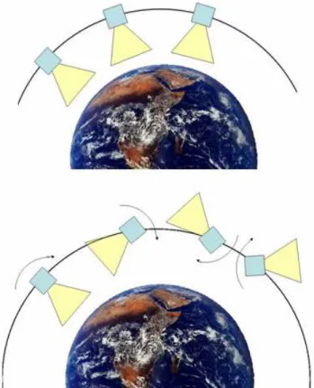
tion for which we provide count rate estimates in Sect. 3. To achieve wider fields of view, an array of such modules is required, synthesizing FOV widths which are multiples of 45.8◦(Table 6). Note that each module in such arrangements will carry an MCP detector, so that the expected count rates from each detector will remain within the limits discussed in Sect. 3. Although “square” arrangements (e.g. 2×2 or 3×3 modules) provide a larger instantaneous field of view for three-axis stabilised platforms, a 1×3 module instrument could be used to reduce mass, cost and complexity (Fig. 10) for operation on a scanning platform. The two alternative pointing schemes for this WFAI spacecraft are illustrated in Fig. 11.
Table 6 also summarises the length of time that various WFAI configurations view a point in the auroral zone, assum-ing that the spacecraft vector is directed through the centre of a 5374 km diameter auroral oval, with the instrument fixed pointing to nadir such that it scans across the oval (the ver-tical distance from the aurora to the spacecraft was assumed to be 690 km). While a single module with a 45.8◦FOV can observe a particular position for 100 s per orbit, significantly longer observations are possible by adding further modules to synthesise a wider field of view. With observation periods of several hundred seconds per orbit possible at time reso-lutions ranging from 3 s to tenths of seconds or better, the WFAI design will permit detailed studies of the dynamics of the aurora at very small spatial scales.
6.2 Electron shielding
A nadir-pointing auroral imager has to contend with a large upward-moving electron flux which must be effectively sup-pressed to minimise imager background. There are three in-built electron attenuation mechanisms in the WFAI design: (a) the low transmission of the MCP optics to a particle flux; (b) the conventional operation of the MCP detector with a high negative input potential (∼−4 kV) which renders the de-tector insensitive to electrons with energies below 4 keV, and (c) the stopping power of the CaF2filter substrate which acts
as a barrier to electrons and the intense Lyman-α (121.6 nm) emission. Rees (1989) provides data for upward-moving electron intensities as a function of altitude (Fig. 3.2.4 in that
Fig. 10 Fig. 10. Imager configuration for scanning the auroral oval,
consist-ing of a 3×1 array of modules, each made up of 4 MCP optic tiles in a 2×2 arrangement (as shown in Fig. 2).
work), based on data from the Dynamics Explorer-2 mission. The data show that electrons with energies in the range 4– 20 keV are of most concern for the current application. The extrapolated range R (mg cm−2) of an electron of energy E
(MeV) in a solid is independent of atomic number and given by
R = 412E1.265−0.0954 ln E(0.01 < E < 3), (7) (Zombeck, 1989). The density of CaF2is 3.19 g cm−3. We
obtain a range of only 2.13 µm for 20 keV electrons, and 42 µm for 100 keV electrons. These ranges should be com-pared with a likely CaF2filter substrate thickness of at least
0.5 mm (as assumed in the sensitivity calculations above). Thus, total attenuation of the upward moving electron flux is achieved by the CaF2alone. There is no requirement for
either a magnetic or electrostatic particle diverter. Careful design of the detector housing will be required to ensure that there is no leak path for electrons around the filter, and to pre-vent the admission of photons generated by electron impact along the instrument optical path. In the latter case, the de-sign of the optics (with channels 1 mm in length) minimises the surface area over which electrons can interact, and thus minimises the electron-generated photon flux.
6.3 Detector resource requirements
The power requirements of lower specification MCP detec-tors based on existing charge division readout technologies with flight qualified components, are typically 6.5 W (Lap-ington et al., 2003), representing the total power consump-tion of the detector system including the MCP high volt-age supply, signal preamplifiers, shaping amplifiers, ADCs, FPGA-based digital processing and digital interfacing to the spacecraft bus. Power requirements for the generic technol-ogy discussed in Sect. 5.1, with its miniaturized, low power ASIC front-end electronics and integrated digital processing on FPGA, is expected to be similar. The estimated mass of
Fig. 11. Top: Imager mounted on a three-axis stabilised (despun) platform, with FOV directed toward nadir. Bottom: Spin stabilised spacecraft, imager FOV is scanned over Earth.
a single module is less than 1 kg (including optics, electron-ics and a 20% contingency). As a consequence of its compact low mass design, the WFAI is expected to be compatible with a wide range of future mission opportunities.
Due to the high intrinsic brightness of the auroral emission and the high resolution of the image, the data rate is likely to be high (approximately 80 Mbit s−1, including 10 bit digiti-sation each for X and Y positions, 6 bits for charge, and 8 bit for time encoding). On-board data compression schemes will therefore be an important element of the instrument design, and will be the subject of a future study.
7 Discussion
Despite obvious imperfections in the prototype which lead to distortions in the cross arms and a broadening of the fo-cal spot, the FWHM of the true focus is 2.8◦±0.1◦, corre-sponding to a 39×39 km (±6.4 km) footprint from an 800 km orbit. This figure places a lower limit on the performance possible from an MCP optic based imager, since the proto-type optic was manufactured purely to illustrate the feasibil-ity of slumping MCP optics to radii of only a few cm. Ex-tensive development work in optic production has been un-dertaken by Photonis SAS with funding from the European
Fig. 12. Optical microscope image showing a single multifibre from a recen
Fig. 12. Optical microscope image showing a single multifibre from a recently produced MCP optic. The individual channels have a width of 100 µm and length of 1 mm. The channel pitch (spacing) is 133 µm. Distortions are evident at the corner of the multifibre due to compression when the individual multifibres are fused together during manufacture. However, they occupy less than 1% of the total surface area and do not significantly affect the quality of focus.
Space Agency (see, for example, work reported by Bavdaz et al., 2004). We have recently received a batch of MCP optics produced for the WFAI development programme using the upgraded manufacturing facilities at Photonis. Early results suggest significant improvements in performance. Optical microscopy shows that the channel regularity in these MCPs is much improved compared to the prototype (see Fig. 12). X-ray point-to-point focusing with a flat MCP from the new batch indicates that the line foci have a FWHM of 5.0±0.3 arcminutes, corresponding to a resolution of 1 km for auroral emission imaged at nadir from an altitude of 800 km. Al-though errors in the figure introduced during the slumping process can be expected to degrade the FWHM value, the goal of 25×25 km spatial resolution from 800 km is clearly achievable. We have also shown that slumped MCP, planar readout detector technology is capable of satisfying the sen-sitivity, dynamic range, focal plane curvature and spatial res-olution requirements of the WFAI instrument.
This paper has been concerned with the performance of an auroral imager in polar LEO. Other mission concepts make use of highly elliptical orbits, with apogee in excess of 6 RE, from which the Earth’s auroral oval subtends an angle of 3◦. It is interesting to consider the potential of MCP optics at such altitudes, in the context of terrestrial missions and in-struments deployed to Jupiter or Saturn, where high altitudes are required to image the extent of the auroral zones. The spatial resolution of our prototype optic corresponds to a cell size of 1670 km at 6 RE– clearly insufficient to provide use-ful data for the studies outlined above. However, as we have noted, this prototype is not representative of the “state of the
art” in MCP optic production. For the MCP defined in Ta-ble 4, the resolution limit is 0.1◦, corresponding to a cell size of 67 km at 6 RE, and the 5 arcminute resolution of the new flat MCP discussed briefly above corresponds to a cell size of approximately 56 km at the same distance. Further improve-ments are possible, since the theoretical limit to the spatial resolution of an MCP optic is determined by the angle sub-tended by a channel as viewed from the focal plane, or D/f , where f is the focal length of the optic. By reducing the pore size to 35 µm, cell sizes of 27 km may be resolved from the same altitude. As noted in Table 3, MCP optics with channel diameters significantly smaller than this have been demon-strated in laboratory tests, so that high resolution imaging from considerable altitudes becomes possible with this tech-nology. This optical performance, combined with the com-pact size and low mass of the instrument, provides, for the first time, the capability to perform high resolution wide field auroral imaging in both low and high altitude Earth orbits, and opens the way to practical, compact instruments which can be deployed on deep space missions to the outer planets.
8 Future work
In separate experiments, we have demonstrated the focusing of parallel beams of FUV radiation with a spatial resolution that satisfies the requirements of high resolution, wide field imaging in Low Earth Orbit (summarised in Table 1), and we have shown that an MCP detector can meet the goals of the WFAI concept in terms of dynamic range, absolute sensitiv-ity and image resolution. We identify three key goals for the next phase of our development programme:
1. End-to-end testing of an MCP optic and WFAI-type
de-tector. In the current work, data for FUV focusing were
obtained using a standard laboratory detector. In the next phase of this work, an MCP optic will be coupled with the WFAI-type detector described in Sect. 5 to ver-ify the results of our current work, showing that the end-to-end performance of the instrument meets the goals of the WFAI concept.
2. Practical demonstration of MCP optic alignment. To generate the required field of view, a WFAI instrument will comprise four MCP optics tiled to form a single spherical surface as described in Sect. 6. These optical elements must be precisely aligned to ensure that the spatial resolution of the assembly preserves that of the individual elements (i.e. that the assembly performs as a larger, single MCP optic).
3. Demonstration of wide-band filter performance. The construction and performance (transmission, out-of-band blocking and response for wide angles of accep-tance) of DE-1 type bandpass filters discussed in Sect. 2
will be verified by introducing appropriate filter ele-ments into the end-to-end demonstrator produced for task (1).
These tasks require the modification of our MCP detector and MCP optic laboratory facilities. This upgrading is currently in progress, and the results of the work packages summarised above will be presented in a future paper.
9 Summary
Microchannel plate optics offer a practical method for meet-ing the wide field of view and high spatial resolution re-quirements of future auroral imaging missions from LEO in a highly compact, low mass package. We have demonstrated the focussing of a parallel beam of Lyman-alpha UV light by a prototype MCP optic, and a preliminary design for a modular auroral imager based on this technology has been presented. The design of the instrument can be tailored to the nature of the spacecraft stabilisation method. In the case of a 3-axis stabilised platform, a number of modules are re-quired to synthesise the entire field of view instantaneously. In the case of a spin-stabilised platform, a 1×3 module de-sign can be used in combination with the scanning motion of the platform to achieve the required field.
An auroral imaging instrument based on this design is cur-rently under consideration for the Chinese KuaFu-B space-craft (Donovan et al., 20071; Tu et al., 2007).
Acknowledgements. This work was supported by PPARC grant
PPA/G/0/2003/00013. We thank the Leicester Physics Department workshop for their efforts in upgrading the X-ray long beamline facility. F. J. Hamilton acknowledges the receipt of a Departmental studentship. S. W. H. Cowley was supported for part of this study by a Royal Society Leverhulme Trust Senior Research Fellowship. We thank the referees for useful comments provided during the prepa-ration of this paper.
Topical Editor I. A. Daglis thanks two referees for their help in evaluating this paper.
References
Barstow, M. A. and Sansom, A. E.: The ROSAT WFC imaging detectors, Proc. SPIE, 1344, 244–254, 1990.
Bavdaz, M., Lumb, D., Peacock, A., Beijersbergen, M., and Kraft, S.: Status of x-ray optics development for the XEUS Mission, Proc. SPIE, 5488, 829–836, 2004.
Brittnacher, M., Spann, J., Parks, G., and Germany, G.: Auroral ob-servations by the polar ultraviolet imager (UVI), Adv. Sp. Res., 20(4–5), 1037–1042, 1997.
1Donovan, E., Trondsen T., Spann, J., Liu, W., Spanswick,
E., Lester, M., Tu, C.-Y., Ridley, A., Henderson, M., Immel, T., Syrj¨asuo, M., Sofko, G., Cogger, L., Murphree, J., Rankin, R., Pulkkinen, T., Sigwarth, J., and Mende, S.: Global Auroral Imaging in the ILWS Era, Adv. Space Res., submitted, 2007.
Brunton, A. N., Fraser, G. W., Lees, J. E., Feller, W. B., and White, P. L.: X-ray focusing with 11mm square pore microchannel plates, Proc. SPIE, 2159, 40–49, 1995.
Brunton, A. N., Fraser, G. W., Lees, J. E., and Turcu, I. C .E.: Metrology and modelling of microchannel plate x-ray optics, Appl. Opt., 36, 5461–5470, 1997.
Brunton, A. N., Martin, A. P., Fraser, G. W., and Feller, W. B.: A study of 8.5µm microchannel plate X-ray optics, Nucl. Instr. Meth., A431, 1, 356–365, 1999.
Carlson, C. W., Pfaff, R. F., and Watzin, J. G.: The Fast Auroral SnapshoT (FAST) mission, Geophys. Res. Lett., 25, 12, 2013– 2016, 1998.
Doe, R. A., Kelly, J. D., Lummerzheim, D., Parks, G. K., Brit-tnacher, M. J., Germany, G. A., and Spann, J.: Initial comparison of POLAR UVI and Sondrestrom IS radar estimates for auroral electron energy flux, Geophys. Res. Lett., 24-8, 999–1002, 1997. Frank, L. A., Craven, J. D., Ackerson, K. L., English, M. R., Eather, R. H., and Carovillano, R. L.: Global Auroral Imaging Instru-mentation for the Dynamics Explorer Mission, Space Sci. Inst., 5, 369–393, 1981.
Frank, L. A., Sigwarth, J. B., Craven, J. D., Cravens, J. P., Dolan, J. S., Dvorsky, M. R., Hardebeck, P. K., Harvey, J. D., and Muller, D. W.: The visible imaging system (VIS) for the Polar spacecraft, Space Sci. Rev., 71, 297–328, 1995.
Fraser, G. W., Pain, M. T., Lees, J. E., and Pearson, J. F.: The opera-tion of microchannel plates at high count rates, Nucl. Inst. Meth., A306, 247–260, 1991.
Fraser, G. W., Brunton, A. N., Lees, J. E., Pearson, J. F., and Feller, W. B.: X-ray focusing using square-pore microchannel plates First observation of cruxiform image structure, Nucl. Inst. Meth., A324, 404–407, 1993a.
Fraser, G. W., Pain, M. T., and Lees, J. E.: Microchannel plate operation at high count rates: further studies, Nucl. Inst. Meth., A327, 328–336, 1993b.
Fraser, G. W., Brunton, A. N., Lees, J. E., Pearson, J. F., Willingale, R., Emberson, D. L., Feller, W. B., Stedman, M., and Haycocks, J.: Development of microchannel plate (MCP) x-ray optics, Proc. SPIE, 2011, 215–226, 1994.
Fraser, G. W., Brunton, A. N., Bannister, N. P., Pearson, J. F., Ward, M., Stevenson, T. J., Watson, D. J., Warwick, R., Whitehead, S., O’Brian, P., White, N., Jahoda, K., Black, K., Hunter, S. D., Deines-Jones, P., Priedhorsky, W. C., Brumby, S. P., Borozdin, K. N., Vestrand, T., Fabian, A. C., Nugent, K. A., Peele, A. G., Irv-ing, T. H., Price, S., Eckersley, S., Renouf, I., Smith, M., Parmar, A. N., McHardy, I. M., Uttley, P., and Lawrence, A.: LOBSTER-ISS: an imaging x-ray all-sky monitor for the International Space Station, Proc. SPIE, 4497, 115–126, 2002.
Frey, H. U., Mende, S. B., Carlson, C. W., Gerard, J.-C., Hubert, B., Spann, J., Gladstone, R., and Immel, T. J.: The electron and proton aurora as seen by IMAGE-FUV and FAST, Geophys. Res. Lett., 28(6), 1135–1138, 2001.
Germany, G. A., Parks, G. K., Brittnacher, M. J., Spann, J. F., Cum-nock, J., Lummerzheim, D., Rich, F., and Richards, P. G.: Energy Characterization of a Dynamic Auroral Event Using GGS UVI Images, in: Geospace Mass and Energy Flow: Results from the International Solar-Terrestrial Physics Program, edited by: Hor-witz, J., Gallagher, D., and Peterson, W., AGU, 143–148, 1998. Greenwald, R. A., Baker, K. B., Dudeney, J. R., Pinnock, M., Jones,
Hanuise, C., Hunsucker, R. D., Sofko, G., Koehler, J., Nielsen, E., Pellinen, R., Walker, A. D. M., Sato, N., and Yamagishi, H.: DARN/SuperDARN – a global view of the dynamics of high-latitude convection, Space Sci. Rev., 71, 761–796, 1995. Lapington, J. S.: The effects of secondary electron emission on
the operation of position sensitive anodes, Nucl. Instrum. Meth., A392, 336–340, 1997.
Lapington, J. S., Chakrabarti, S., Cook, T., Goeke, R. F., Gsell, J. C., and Gsell, V. T.: A Detector System for SPIDR - A Mission to perform Spectroscopy and Photometry of the IGM’s Diffuse radiation, Proc. SPIE, 4854, 593–601, 2003.
Lapington, J. S.: Developments in high count rate microchannel plate detectors, Proc. SPIE, 5898, 85–94, 2005.
Laufer, A. H., Pirog, J. A., and McNesby, J. R.: Effect of Temper-ature on the Vacuum Ultraviolet Transmittance of Lithium Flu-oride, Calcium FluFlu-oride, Barium FluFlu-oride, and Sapphire, J. Opt. Soc. Am., 55, 64–66, 1965.
McPhate, J. B., Siegmund, O. H. W., Gaines, G., Vallerga, J. V., and Hull, J.: The Cosmic Origins Spectrograph FUV Detector, Proc. SPIE, 4139, 25–33, 2000.
Mende, S. B., Heetderks, H., Frey, H. U., Lampton, M., Gellar, S. P., Abiad, R., Siegmund, O. H. W., Tremsin, A. S., Spann, J., Dougani, H., Fuselier, S. A., Magoncelli, A. L., Bumala, M. B., Murphree, S., and Trondsen, T.: Far Ultraviolet Imaging from the IMAGE Spacecraft: 2. Wideband FUV Imaging, Space Sci. Rev., 91(1–2), 271–285, 2000.
Milan, S. E., Lester, M., Cowley, S. W. H., Oksavik, K., Brittnacher, M., Greenwald, R. A., Sofko, G., and Villain, J.-P.: Variations in the polar cap area during two substorm cycles, Ann. Geophys., 21, 1121–1140, 2003,
http://www.ann-geophys.net/21/1121/2003/.
Murphree, J. S., King, R. A., Payne, T., Smith, K., Reid, D., Adema, J., Gordon, B., and Wlochowicz, R.: The Freja ultraviolet im-ager, Space Sci. Rev., 70, 421–446, 1994.
Nussey, J.: Terrestrial and Space-based Applications of Microchan-nel Plate X-ray Optics, University of Leicester, Ph.D. thesis, 2005.
Price, G. J., Brunton, A. N., Fraser, G. W., Bavdaz, M., Beijersber-gen, M. W., Boutot, J.-P., Fairbend, R., Flyckt, S.-O., Peacock, A., and Tomaselli, E.: Hard X-ray imaging with microchannel plate optics, Nucl. Inst. Meth., A490, 290–298, 2002.
Rees, M. H.: Physics and chemistry of the upper atmosphere, Cam-bridge University Press, 1989.
Rich, F. J., Hardy, D. A., and Gussenhoven, M. S.: Enhanced ionosphere-magnetosphere data from the DMSP satellites, EOS (ISSN 0096-3941), 66, 513–514, 1985.
Ruohoniemi, J. M. and Baker, K. B.: Large-scale imaging of high-latitude convection with Super Duel Auroral Radar Network HF radar observations, J. Geophys. Res., 103, 20 797–20 811, 1998. Siegmund, O. H. W., Cully, S., Warren, J., Gaines, G. A., Pried-horsky, W., and Bloch, J.: Highly curved microchannel plates, Proc.SPIE, 1344, 346–354, 1990.
Siegmund, O. H. W., Gummin, M., Stock, J., Naletto, G., Gaines, G., Raffanti, R., Hull, J., Abiad, R., Rodriguez-Bell, T., Magon-celli, T., Jelinsky, P., Donakowski, W., and Kromer, K.: Per-formance of the double delay line microchannel plate detectors for the Far Ultraviolet Spectroscopic Explorer, Proc.SPIE, 3114, 283–294, 1997.
Simons, D. G., Fraser, G. W., de Korte, P. A. J., Pearson, J. F., and de Jong, L.: UV and XUV quantum detection efficiencies of CsI-coated microchannel plates, NIM A, 261, 579–586, 1987. Torr, M. R., Torr, D. G., Zukic, M., Johnson, R. B., Ajello, J.,
Banks, P., Clark, K., Cole, K., Keffer, C., Parks, G., Tsurutani, B., and Spann, J.: A Far Ultraviolet Imager for the International Solar-Terrestrial Physics Mission, Space Sci. Rev., 71, 329–383, 1995.
Tremsin, A. S. and Siegmund, O. H. W.: UV Radiation Resistance and Solar Blindness of CsI and KBr Photocathodes, IEEE Trans. Nucl. Sci., 48(3), 421–425, 2001.
Tu, C.-Y., Schwenn, R., Donovan, E., Marsch, E., Wang, J.-S., Xia, L.-D., and Zhang, Y.-W.: Space Weather Explorer – The KuaFu Mission. Adv. Space Res., in press, 2007.
Vallerga, J. Zaninovich, J., Welsh, B., Siegmund, O., McPhate, J., Hull, J., Gaines, G., and Buzasi D.: The FUV detector for the cosmic origins spectrograph on the Hubble Space Telescope, Nucl. Inst. Meth., A477, 551–555, 2002.
Zombeck, M. V.: Handbook of Space Astronomy and Astrophysics, Cambridge University Press, 1989.
Zukic, M., Torr, D. G., Kim, J., Spann, J. F., and Torr, M. R.: Fil-ters for the International Solar Terrestrial Physics Mission far-ultraviolet imager, Opt. Eng., 32, 3069–3074, 1993.