Publisher’s version / Version de l'éditeur:
Proceedings of the AREMA 2004 Annual Conferences, 2004-09
READ THESE TERMS AND CONDITIONS CAREFULLY BEFORE USING THIS WEBSITE. https://nrc-publications.canada.ca/eng/copyright
Vous avez des questions? Nous pouvons vous aider. Pour communiquer directement avec un auteur, consultez la première page de la revue dans laquelle son article a été publié afin de trouver ses coordonnées. Si vous n’arrivez pas à les repérer, communiquez avec nous à PublicationsArchive-ArchivesPublications@nrc-cnrc.gc.ca.
Questions? Contact the NRC Publications Archive team at
PublicationsArchive-ArchivesPublications@nrc-cnrc.gc.ca. If you wish to email the authors directly, please see the first page of the publication for their contact information.
Archives des publications du CNRC
This publication could be one of several versions: author’s original, accepted manuscript or the publisher’s version. / La version de cette publication peut être l’une des suivantes : la version prépublication de l’auteur, la version acceptée du manuscrit ou la version de l’éditeur.
Access and use of this website and the material on it are subject to the Terms and Conditions set forth at
Control of rolling contact fatigue of rails
Magel, Eric; Sroba, Peter; Sawley, Kevin; Kalousek, Joe
https://publications-cnrc.canada.ca/fra/droits
L’accès à ce site Web et l’utilisation de son contenu sont assujettis aux conditions présentées dans le site LISEZ CES CONDITIONS ATTENTIVEMENT AVANT D’UTILISER CE SITE WEB.
NRC Publications Record / Notice d'Archives des publications de CNRC: https://nrc-publications.canada.ca/eng/view/object/?id=d31954d8-17cd-48cd-875f-eadb1ebc3735 https://publications-cnrc.canada.ca/fra/voir/objet/?id=d31954d8-17cd-48cd-875f-eadb1ebc3735
Control of Rolling Contact Fatigue of Rails
Eric Magel, Peter Sroba, Kevin Sawley and Joe Kalousek Centre for Surface Transportation Technology
National Research Council Canada #511, 609 – 14th Street NW Calgary, Alberta, Canada T2N 2A1
Telephone: 403.292-6404 Fax: 403.292.6438 E-mail: Eric.Magel@nrc-cnrc.gc.ca Peter.Sroba@nrc-cnrc.gc.ca Kevin.Sawley@nrc-cnrc.gc.ca Joe.Kalousek@nrc-cnrc.gc.ca Number of words: 6849
Control of Rolling Contact Fatigue in Rails
Eric Magel, Peter Sroba, Kevin Sawley and Joe Kalousek Centre for Surface Transportation Technology, Canada
National Research Council, Canada
Abstract
Despite continuing improvements in rail steels, inspection, lubrication and grinding, rolling contact fatigue (RCF) remains a key cause of rail maintenance and rail replacement. Exploiting existing techniques and developing improved ones for prediction, identification and treatment of RCF is essential for ensuring safety, increasing rail life and reducing maintenance and capital costs. This paper reviews the different types of RCF found on rails, and the physical and operating parameters that influence RCF. Their influence on RCF is discussed in the light of field experience and emerging models of wheel-rail interaction and rail damage. The important role of wheel/rail tractions in RCF formation is highlighted and the suggestion made that normal contact stress alone is insufficient for modeling RCF. An example of predicted RCF for three rail profiles and several rail hardness values is given.
The paper concludes by providing practical guidelines for the economic and safe control of RCF. It also discusses potential vehicle/track system improvements to reduce the risk of RCF crack
development, and highlights emerging and anticipated developments that will further improve a railway’s ability to prevent and treat RCF.
1 INTRODUCTION
Rolling contact fatigue (RCF) is a family of damage phenomena that appear on and in rails due to
overstressing of the rail material. This damage may appear first on the surface (e.g. head checks, shelling, squats) or the subsurface (deep seated shell). In either case, these phenomena are the result of repeated overstressing of the surface or subsurface material by the hundreds or thousands or millions of intense wheel-rail contact cycles.
The problem of rolling contact fatigue in rails grew in size both domestically and internationally through the 1990s, and was brought to worldwide attention through the loss of life in the Hatfield (UK) derailment in 2000. According to FRA statistics, in the eight years from 1995 to 2002, rolling contact fatigue was strongly implicated in 122 derailments, and may have contributed to 160 more.
Beyond the safety implications, there is a substantial economic cost associated with RCF. A European study [1] suggests that the cost of RCF to the European railway network, including inspection, train delay, rail replacements and weld repair, rail grinding and derailments, is about 300 million € per year. The cost of RCF to the North American rail industry is believed to be a significantly greater amount.
Two key processes govern RCF - crack initiation and crack propagation. These processes are governed by a number of factors including environmental conditions, rail and wheel profiles, track curvatures, grades, lubrication practices, rail metallurgy, vehicle characteristics, track geometry errors, and rail grinding practices. They all play a role in the formation of RCF and – inversely – can be used to control and minimize RCF.
The amplitude and position of the crack initiating stresses varies depending on the contact geometry, load, and friction conditions. Under high friction conditions shear stresses are large but very shallow. Under low friction conditions, the peak shear stress decreases but extends deeper into the railhead. The result is that some RCF defects are initiated at the surface and others below the surface.
2 SURFACE INITIATED DEFECTS
Fatigue of the rail surface is an extremely common problem that affects virtually every railroad, from light axle load transits to the most heavily loaded freight railroads. There is a regular progression in the
development of these defects, from light checking to regular cracking to light shelling, to heavy shelling. Examples for the high and low rails are shown in Figure 1.
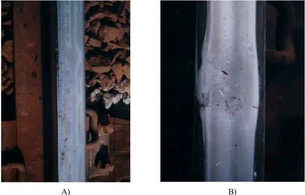
Rolling contact fatigue can also be a cause of corrugation (Figure 2A). Although RCF may initiate randomly along the rail, under conditions of consistent train speeds the passing wheelsets react to the RCF perturbations and set up a regular pattern of defects.
Another surface fatigue initiated defect is the squat (Figure 2B), a defect that is most common on high-speed commuter railroads, but for which many examples can be found on freight systems. The only successful technique for preventing squats has been to regularly grind a thin skim from the surface of the rail to remove the damaged layer. Ishida [2] has reported good results with rail grinding of squats in Japan.
2.1 Surface crack initiation
A typical heavy haul rail encounters about three million wheel contacts every 100MGT. While most of these contacts can be borne without damage, a certain fraction plastically deforms the steel in the direction of the applied tractions. Each increment of deformation “ratchets” the surface layer [3] until it eventually exhausts the available ductility of the steel. The steel then fractures and a surface crack is generated [4]. The combinations of normal contact stress (Po), surface tractions (T/N) and shear strength of the steel (K)
required to generate an increment of fatigue are summarized in Johnson’s Shakedown Diagram (Figure 3). Contacts to the left and below lines A and C are benign while those to the right and above lines B and C increment the surface fatigue process.
It must be emphasized that RCF cannot be evaluated based on normal contact stress alone since the interdependence with tractions and material strength is too intimate. Assessing wheel/rail performance with respect to contact fatigue requires consideration of all three parameters.
2.1.1 Normal stress (P
o) at wheel/rail contact
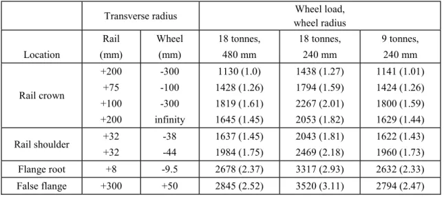
Normal contact stress is a function of four main factors; wheel diameter, wheel load (including possible dynamic loading), the transverse rail profile and the transverse profile of the wheel. According to Hertz’s elastic contact equations, doubling of wheel load will increase contact stress by about 27%, a tripling increases contact stress by 44%. All other things being equal, the effect of wheel diameter is similarly limited to a 1/3rd-power function. But the transverse geometry of the wheel and rail profiles has a much stronger effect on contact stress – see Table 1. If one includes undesirable deviations from the design (e.g. as provided by the supplier), poor blending of grinding facets, rotation of the rail and other factors, contact stress can vary by 300% or more in real world conditions. References 5 and 6 discuss strategies for developing rail profiles to control contact stress.
In practice there are several conditions that influence the position of the wheel on the rail and therefore impact the contact stress:
• Track Gauge – Changing the distance between the two rails usually modifies the position and
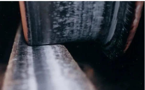
geometry of the wheel/rail contact. Tight gauge in tangent track promotes gauge corner contact, trucks hunting and RCF, whereas at nominal gauge more of the contacts will be carried towards the crown of the rail where contact conditions are usually less severe. In curves, controlling wide gauge is essential for mitigating low rail damage associated with hollow wheels (Figure 4). Wide gauge curves are also more susceptible to dynamic rail rotation, which often contributes to unfavorable contact geometry. • Welds, profile irregularities: The steel in welds invariably has hardness different from that of the
parent rail steels, even with the best post heat-treating efforts. In welds where this difference is large (say 30 points Brinnell), either softer or harder, the weld will deform greater or less, respectively.
Softer welds typically produce a dip with accelerated development of RCF (Figure 5A) and harder welds (Figure 5B) produce high spots that excite vertical wheelset dynamics and are responsible for RCF damage that develops adjacent to that weld.
• Other factors that affect contact stress include cant excess and cant deficiency, hunting of wheelsets in tangent track and mild curves, track geometry errors, string-lining forces on grades, tie-plate cut-in and poor fastening, uneven car loading, skewed trucks and mismatched wheel diameters.
2.1.2 Rail/wheel tractions (T/N)
Rail/wheel traction develops due to a small relative slip between the rail and wheel that shears the interfacial layer in the contact zone. The level of slip (also known as creep) depends on the curving and traction demands. These creep forces, or tractions, cannot exceed the available adhesion – the vertical force on the wheel times the friction coefficient. Controlling tractions is therefore a process of controlling the properties of the interfacial layer and minimizing creepage.
The interfacial layer is a mixture of wear debris and environmental contaminants that separate the wheel and rail surfaces. A lubricant, by virtue of its low shear strength, can dramatically reduce the peak traction force as compared with a dry surface. This is particularly effective at the rail gauge face to control wear but at the top of rail, a friction coefficient of above 0.3 is required to facilitate braking and traction. As seen in Figure 3, operating with higher friction coefficients dramatically reduces the shakedown threshold and therefore increases the initiation of RCF. A more detailed discussion of interfacial layers for
rail/wheel systems is found in Reference 8.
Traction (T) has lateral (Flat) and longitudinal (Flong) force components: T = sqrt( Flat2 + Flong2 ) which at the
limit approaches the wheel/rail friction coefficient. The actual traction ratio T/N for any given wheel/rail combination depends on several operating parameters including:
• Curving requirements: when a truck negotiates a curve the wheelsets are restricted by the suspension from aligning radially to the curve. The leading wheelset typically flanges against the outside rail
with a significant yaw angle, with the trailing wheelset (in a mild curve) being more or less central in the track with a small yaw angle. The exact positions will vary depending upon the specific
conditions but in most cases, angle of attack and creepages (both lateral and longitudinal) increase with curvature and truck wheelbase. Accordingly, the rate and severity of RCF formation in curves increases with curvature and truck wheelbase.
• Bogie Suspension: a stiff bogie resists displacement of the wheelset with respect to the truck frame. The more flexible the suspension, the greater the potential for favorable steering moments to reduce the yaw angle in curves and thereby reduce RCF. However, a more flexible truck has a greater ability to respond to unfavorable steering moments and increase the yaw angle [6], especially in the case of trucks that have been poorly maintained and are running with a number of worn-out components. A number of trucks have been developed to improve upon the limited curving performance of the standard three-piece truck but with improved stability in tangent track [10].
• Friction coefficient: Minimizing friction coefficient reduces the peak tractive force but
simultaneously reduces the steering moments that develop. The result is a measurable impact on the yaw angles [11]. Reference 12 recommends that the difference in top-of-rail (TOR) friction
coefficients should not be less than 0.3 and the difference in TOR value between the two rails should not exceed 0.1. TOR friction control should be considered for track where high friction problems, such as weak track, high TOR wear rates and wheel climb concerns exist.
• Cant Deficiency: The additional sideways load on the truck from cant deficiency changes the
orientation of axles. Typically, in the case of high speed trains running on mild curves with large cant deficiency, both the leading and trailing wheelsets offset heavily to the outside rail, sometimes to the extent of flanging (depending on the profiles). This lateral shift is much greater than when running at balance speed in the same mild curve. The result is increasing (longitudinal) tractions with cant deficiency and high potential for RCF of the mid-gauge position on the rail.
2.1.3 Rail metallurgy
The effect of rail metallurgy on RCF is complex. In laboratory studies two conclusions generally recur. First, for a given level of hardness, pearlitic steels are more resistant to RCF than are other structures such as bainite and martensite. Second, for any given type of steel structure, resistance to RCF increases with hardness.
The problem is demonstrating these laboratory results in service tests, where many factors interact to influence RCF: rail hardness, detailed wheel and rail profiles, lateral and longitudinal wheelset dynamics (which depend on the truck design and state of wear), and possibly transient dynamic effects at small lateral track geometry deviations. RCF is particularly sensitive to wheel and rail profiles, and
inappropriate or uncontrolled profiles can completely mask effects of metallurgy. In the UK, the general experience has been that high strength steels are more prone to forming RCF – a finding that can be explained by the high stress rail section employed and the failure of the hard steels to wear or flow to a lower stress shape. It has also been their experience that if the rail is initially ground to a lower-stress shape, then it is much more resistant to RCF than the softer steels.
While there is no consensus on the effect of rail microstructure on RCF, the strength of rail steel in shear is understood to be the main factor that controls RCF in rails, and consideration of this parameter helps explain microstructure effects. The shear yield strength of as-manufactured rail is easily measured in the laboratory, and is seen to increase with hardness. However, it is the shear yield strength developed in the work-hardened rail surface layers that is likely to be critical, and different microstructures work-harden at different rates. As an example, laboratory tests indicate that bainitic steels work-harden less than pearlitic steels under rolling contact conditions. Thus, while bainitic steels may have higher bulk strength than pearlitic steels, pearlitic steels likely develop work-hardened layers with even greater strength. This may explain why tests with other microstructures, such as bainitic and martensitic steels, have produced conflicting results.
Most commonly, the value of shear yield strength K is calculated as the hardness (converted from Brinnell to Vickers) divided by 6.0. The values commonly used by the authors for shakedown analysis are
summarized in Table 2.
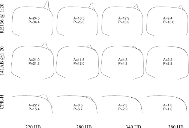
The impact of shear strength on RCF initiation is readily obtained using the shakedown model of Figure 3. The shakedown limit increases directly with K such that an HE (hyper-eutectoid) premium steel can withstand contact stresses about 45% greater than a standard rail steel without yielding. The practical implication of this is often more than a 45% improvement in RCF resistance because of the dependence of stress on profile shape. In Figure 7 we see the predicted distributions of rolling contact fatigue damage (see Reference 5 for details) on the high rail of a 4-degree curve for three different rail shapes (the CPR-H is a template designed specifically for the Canadian Pacific’s Western Line). These are plotted for four different rail hardnesses. The harder steels reduce significantly the number of contacts that exceed shakedown, thereby reducing the probability of crack initiation (and also the rate of propagation). It should be noted that without proper lubrication, the CPR-H will see considerably greater rates of gauge-face wear.
Surface Crack propagation
Once a crack has initiated, the rate at which it progresses into the surface is influenced by a large number of considerations. The crack propagation rates are dependent on the propagation stresses and on the ability of the steel to resist propagation. Accordingly, the discussions of Sections 2.1.1 and 2.1.2 are still relevant to the propagation process. The metallurgical considerations are many – see Reference 13. The presence of grease and water at the wheel/rail contact play a critical role in the rate and depth of surface crack propagation. If grease or other contaminants seep into the surface cracks, the reduction in crack-face friction allows the faces to slide past each other (Figure 8a), contributing to moderate crack growth rates. Water, with its low viscosity and high surface tension, is drawn into the cracks by capillary action. If the surface crack is oriented in a direction where it drops away from the approaching load, the rolling contact will first seal the crack entrance and then hydraulically pressurize the crack tip (Figure 8b).
This provides a large tensile (i.e. Mode I) stress at the tip, promoting rapid crack propagation. For this reason, crack propagation in dry environments is very different from that in wetter environments. The shear stress in dry environments is intense and very shallow. Surface cracks propagate only about 3-mm deep. Under wet conditions, those surface cracks propagate to a much greater depth (say 7-15 mm), largely due to the hydraulic crack propagation mechanism. According to the crack orientations shown in Figure 6, gauge corner cracks at the high rail (note the dots at the ends of the cracks) will undergo hydraulic propagation and generally be more severe than at the field side of the low rail. This is readily observed in the field in mild curves. The same explanation applies to the observation that field side cracking on the wheel-tread is much more prevalent than flange root cracking.
Note that once the crack reaches a depth of greater than about 8-15mm, it is out of the field of influence of rolling contact stresses. Beyond this depth cracks may continue to propagate due to thermal stresses in the rail (e.g. tensile stresses in cold weather), bending stresses due to wheel loads and residual stresses in the rail from manufacturing processes.
3 SUBSURFACE INITIATED RCF DEFECTS
Only one of the many subsurface defects that occur in rails can be considered a rolling contact fatigue defect. While vertical and horizontal split heads and tache ovales have sometimes been classified as RCF defects, they are more appropriately dealt with as metallurgical defects since contact stresses have little influence on their initiation or propagation. In contrast, deep-seated shells are a direct response to excessive contact loads at the extreme gauge corner that cause the rail to fail along a shear or “slip” line (Figure 9). In steels with metallurgical imperfections, the deep-seated shell can initiate a transverse defect (Figure 10C). Since rolling contact stresses are only active near the surface, the transverse defect must be propagated by bending, residual and thermal stresses.
Deep-seated shells can be minimized through the use of harder steel and rail grinding. Grinding to shift load from the extreme gauge corner is one obvious approach. Rail grinding can also be used to
progressively shift the location of greatest subsurface shear stress through the railhead so that the stress does not have an opportunity to dwell at any given weak spot for an extended period of time. This is especially important in well-lubricated environments where the lack of wear only exacerbates the problem of shear-stress dwelling on vulnerable steels.
4 THE MAGIC WEAR RATE AND RAIL GRINDING
A key to understanding the benefits of any strategy to monitor or treat RCF is to appreciate the basic features of crack initiation and growth.
A. The process of initiating a crack in an initially clean surface takes a finite number of loading cycles to occur – it is not instantaneous. Early field studies suggested that crack initiation takes place over a period of 3-6 MGT [15]. Metallurgical analysis showed that newly initiated surface cracks are a fraction of a millimeter in length and propagate at an angle of 5 to 15 degrees with respect to the surface.
B. As per classical fracture mechanics, these short surface micro-cracks at first propagate slow then fast and slow again [16]. The cracks propagate fastest at the intermediate length of about 5-10 mm and depth of about 1–3 mm. At greater lengths and depth of several millimeters crack propagation proceeds at a relatively slow rate.
Both crack initiation and propagation are impacted by the rate at which material is worn from the surface – which includes wear due to wheel/rail contacts, corrosion, abrasive processes, and maintenance
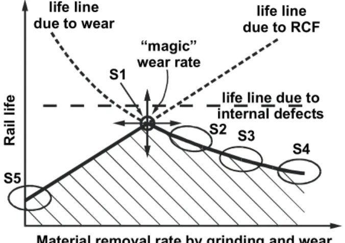
processes such as rail grinding, milling or planing. Continuous or frequent removal of a small amount of surface material truncate existing cracks and can theoretically eliminate surface crack initiation altogether. The optimal situation is to continuously remove just the right amount of metal to control surface crack initiation (and also to inhibit subsurface initiation as per Section 3) and propagation of short cracks when the rate is still slow. This metal removal rate has been called “The Magic Wear Rate” (MWR).
MWR is very dependent on the particular circumstances of the rail and includes all the key parameters that are associated with normal contact stresses, tractions, metallurgy and environment to which a particular rail is exposed (lubrication, moisture, etc.). With respect to curvature, MWR is several times higher in sharp curves than in straight track. MWR can be reduced by using hard clean steel, TOR friction management, and wheel/rail profiles that manage contact stresses and tractions to low levels in both the new and worn state. In track without RCF, the wear rate from passing wheels may be much higher than MWR. In track with RCF, the natural wear rate should be supplemented by grinding. MWR is the lowest rate of metal attrition from rail that keeps rail safe from RCF damage and provides maximum possible life (see Figure 11). Magic wear rate also provides the basis for rail grinding strategies.
4.1 Optimizing the rail grinding process
Rail systems ranging from Mass Transit to High Speed to Heavy Haul require different grinding approaches. Each must consider distribution of curvature, variety/complexity of rolling stock, available track time and grinding equipment and the extent of lubrication and top of rail friction management (if any) in the system. Priorities of the railway management with respect to gauge-face / wheel-flange wear, vehicle dynamic (hunting) performance, corrugations or RCF wheel shelling (where applicable) and rolling contact fatigue must also be factored in. In some systems, grinding to a set of rail profiles that is matched by “worn” wheel profile can balance the conflicting requirements of all four priorities. In other systems, many heavy haul lines for example, the conflicting requirements of gauge face wear and RCF cannot be satisfied. Wear must be controlled by reliable lubrication, and RCF through an appropriate grinding strategy.
• Strategy S1 in Figure 11 is the condition where rolling contact fatigue is controlled by sufficient and frequent material removal by grinding and complementary wear, i.e. the magic wear rate. Experience with preventive grinding shows that this value is about 0.002-0.003” from the top-of-rail and about 0.006” from gauge-corner of high-rail and field-side of low-rail every 15-30 MGT. After the single, high-speed (e.g. 8-10 mph) grinding pass, a clean and properly profiled rail surface is left behind.
Since only a small amount of material is removed the remaining surface, already work hardened with favorable compressive residual stresses, inhibits further deformation and crack initiation. Sharp curves are ground more frequently than mild curves, with tangent rail ground least often. This strategy is suitable for a newly installed rail ground to correct profiles or rail that has been recovered by S2–S4. • S2 represents the preventive-gradual process [17]. By slowing down the machine, increasing the
grinding motor amperage, optimizing the rail grinding patterns and decreasing the grinding interval, the amount of metal removed each cycle can be increased. This strategy is applied to “catch-up” on rail that has existing cracks or poor profiles. Usually a preventive grinding interval of 15-20 MGT is used. Once the rail surface has been cleaned of RCF damage and restored to the desired set of profiles, S1 should be the target.
• S3 is a maintenance grinding practice with longer grinding intervals and more metal removed each time using slow, multiple passes (usually 2 or 3) on some curves. Rail that is single-passed is usually treated at slow speeds (e.g. 4-6 mph). Although this strategy prevents heavy RCF damage, it shortens the life of rail.
• S4 is the case of corrective grinding where rail is usually in an advanced state of RCF damage. Grinding frequency is based on other factors or limitations rather than MGT and is typically much longer than in S1 – S3. Only track with obvious RCF is treated, track without visible damage is not ground. A large quantity of metal is ground off the head of the rail. This is accomplished by many low-speed passes (say 3-7) especially in curves. Removal of the work hardened layer leads to high initial rates of plastic flow, rapid deterioration of rail profiles and accelerated growth of RCF damage that further curtails rail life.
• S5 represents the no-grind philosophy. The only wear occurs from the wheel-rail contact. The rail eventually fails, sometime very quickly, due to rolling contact fatigue. Premium steels in curves and dry environments have successfully withstood several hundred MGT without grinding but the end life was still a fraction of what could be achieved with regular maintenance.
Grinding is a powerful tool for preventing significant RCF development (and removing existing surface RCF) and thereby enhances the safety and economy of railway operations. In addition to removing cracks and the fatigued layer from the surface of the rail it can regularly maintain the optimal rail profiles. Optimal profiles minimize normal contact stresses and reduce shear stresses in the rail by controlling longitudinal, and to some extent, lateral traction forces between wheel and rail. Another important duty of optimal profiles is to spread wear on the wheel tread and reduce wheel hollowing.
Unfortunately, there is no one ideal grinding interval, magic wear rate or set of optimal rail shapes. They can only be determined after first evaluating the features and priorities of the target system (see Reference 18 for an example of this procedure). Based on analysis and measurements of worn wheel and rail profiles of a railway line, the shape of optimal rail profiles can be determined. Before application to the entire system, those profiles should be validated in monitored test sites, together with lubrication and metallurgy that is typical for the system. These test sites also provide a unique opportunity to fine-tune the grinding strategy with respect to metal removal rates and grinding intervals that are consistent with MWR for effective control of RCF damage. Monitoring can also be adjusted to include any other priorities of railway management such as gauge face wear, hunting of vehicles, top of rail friction management, corrugations and so on.
5 CONTROLLING AND TREATING RCF - SUMMARY
A number of practical strategies for minimizing the formation and risk associated with RCF defects are available:
• Implement rail grinding (Section 4) since it is a powerful tool for preventing significant RCF development and is the only effective tool for removing existing RCF.
• Improve the wheel and rail profiles to reduce both contact stress and tractions. Although much of the heavy haul traffic is theoretically restricted by interchange rules, one Class 1 is applying a
custom-designed wheel-profile on its captive coal fleet with the expectation of at least 25% improved wheel life [19].
• Install harder, cleaner rail steels since they are more resistant to both initiation and propagation of cracks that contribute to RCF. The small cost premium that is sometimes attached to the better steels is almost universally a wise investment.
• Manage friction – control the top-of-rail value to 0.3-0.35. Avoid over lubricating the gauge face such that the top-of-rail becomes contaminated, since it not only increases propagation of surface cracks but also poses a safety risk.
• Minimize dynamic loads, especially those associated with track geometry errors that instigate dynamic loads that not only increase contact stress but also lead to rapid, localized deterioration of the profiles and high stress contact geometry (e.g. Figure 12).
• Control track gauge, especially in sharp curves. A survey of rail grinding in the North American heavy haul environment found that the low rail consistently requires more attention from the rail-grinders than the high leg, a situation that is exacerbated by wide gauge and hollow wheels. Curves should not exceed 0.5” wide gauge and tight gauge should be avoided in tangent track.
• Although railways are FRA regulated to regularly inspect track with appropriate equipment, often the inspection information is only indirectly included in the rail-grinding program. Because a clean surface is inherently safer but also improves the reliability of many rail flaw detection processes, rail flaw detection information should be used as part of the planning process for rail grinding.
• Emerging tools for quantifying RCF (e.g. Alternating Current Field Measurement, machine vision systems), and for measuring rail profiles, track stress and a range of other variables should be
progressively included in an integrated risk management / maintenance planning and tracking system. This system would identify and track the highest risk sections of track, assess the maintenance
requirement and costs, and guide the development of an optimized plan for RCF mitigation, rail life extension, maintenance cost reduction and safety enhancement.
• Utilize flexible or self-steering trucks since they can contribute to reduced creepages. Other improvements to the truck to limit vertical dynamics and reduce instability are also helpful. • Optimize super-elevation so that the largest MGT of traffic runs at balanced speed but without
compromising safety for the higher speed trains.
• Remove excessively hollow wheels. The establishment of a hollow wear limit by the AAR should be effective in reducing damage to the field side of the low rail in North America.
• Control tie-plate cut in or fastener problems that allow the rail to rotate dynamically under load. Elastic fasteners should be applied to curves sharper than about 2.5 degrees on heavy haul track.
6 CONTROLLING AND TREATING RCF: VISIONS FOR THE FUTURE
A number of visions are emerging for technologies that may considerably improve the reliability and accuracy of RCF detection and treatment, reduce the cost and improve safety, economy and safety with respect to RCF. Several examples follow:
• In the Netherlands, statistical methods are used to develop a “damage number” D = Dr x Ds x Dp x Dt, where Dr is related to the curve radius, Ds to sleeper type, Dp to rail profile, and Dt to traffic type [20]. The parameters Dr, Ds, Dp and Dt are determined through statistical correlation with a large database that warehouses RCF visual inspection records. Based on the damage number, grinding priorities are assigned. The inclusion of a few additional parameters (such as grade, metallurgy, weld quality, prior maintenance practices etc.) with regular updating might provide a useful and ongoing approach to managing rolling contact fatigue in North America.
• Computer based predictive models of several forms are also being derived. In Europe extremely comprehensive systems are linking multi-body vehicle dynamic, wheel/rail contact, track, crack
initiation and propagation and deformation models to predict the evolution of RCF on the rail [e.g. 21, 22].
• The authors are pursuing the development of a system that, similar to the first approach, would consider a number of factors that influence the fatigue and wear processes and assign “influence coefficients” to each. The approach would be a hybrid of computer modeling and statistical approaches. The numerous inter-relationships between operating, physical and material parameters discussed in this paper will be algorithmically defined in a model to predict the surface damage. This model would be continually supported and calibrated using visual observations of surface condition and increasingly available data streams including rail flaw measurements, frictional data, field tests of the performance of various rail steels and wheel profile measurements. The resultant damage
accumulation could, along with measured rail profiles, feed directly into the rail grinding program to identify the appropriate time and level of effort needed.
• The old axiom that “you can’t manage what you cannot measure” is as valid for RCF as it is for wear or any other damage issue. While there are strong efforts underway to use regular rail profile
measurements to guide rail-grinding programs, these fail to recognize that a crucial component of grinding decisions is the surface condition of the rail. One approach with potential is to quantify rail surface condition with a high-speed machine-vision system that maps the surface, identifies dominant surface features (cracks, shells, squats, flaking, perhaps running bands, facets and grinding marks) and then provides relevant surface quality indices. Although there has already been some success in applying machine vision systems to identify large features like wheel-burns, cracked joint bars, missing rail clips, etc. research and development are still needed to improve the technology for quantifying much smaller and lower contrast features at speed. In addition to the various hardware developments a number of interpretive algorithms will be needed to fulfill this vision.
7 REFERENCES
1. Integrated Study of Rolling Contact Fatigue (ICON) – European Commission DGX111 Brite/Euram III Project, Contract BRPR-CT96-0245 Project Programme, Brussels, 1997-1999
2. M. Ishida, M. Akama, K. Kashiwaya and A. Kapoor, “The current status of theory and practice on rail integrity in Japanese railways – rolling contact fatigue and corrugations”, Fatigue and Fracture Engineering Materials and Structures 26, 2003, pp. 909-919
3. K.L Johnson, “The mechanics of plastic deformation of surface and subsurface layers in rolling and sliding contact”, Material Science Forum: The Role of Subsurface Zone in Wear of Materials, Trans Tech Publications, 1988, pp. 33-40
4. P.E. Bold, M.W. Brown and R.J. Allen, “Shear mode crack growth and rolling contact fatigue”, Wear 144 (1991) pp. 307-317
5. E. Magel and J. Kalousek, “The application of contact mechanics to rail profile design and rail grinding”, Wear 253 (2002) 308-316
6. H.M. Tournay, “Rail/wheel interaction from a track and vehicle design perspective”, IHHA 1999 STS – Conference Wheel/Rail Interface, Moscow 1999.
7. A.D. Hearle and K.L. Johnson, “Cumulative plastic flow in rolling and sliding contact”, Trans. ASME, Ser. E., J. Appl. Mech., 54, 1-7, 1987
8. J. Kalousek, K. Hou, E. Magel and K. Chiddick, “The benefits of friction management - a third body approach”, World Conference on Railway Research, Colorado, June 1996
9. J. Kalousek, “Wheel/rail damage and its relationship to curvature”, Proceedings of 6th International Conference on Contact Mechanics and Wear of Rail/Wheel Systems, Gothenburg Sweden, June 2003 10. B.T. Scales, “Review of Freight Car Bogie Design and Performance”, IHHA Conference on Freight
11. G. Izbinsky, “Detection and rehabilitation of bad acting trucks with angle of attack inspection station”, Presentation at Advanced Rail Management Wheel/Rail Seminar, Chicago, May 1998
12. R. Reiff and D. Creggor " Systems Approach to Best Practice for Wheel and Rail Friction Control" International Heavy Haul Conference 1999
13. P. Ohlund, “Crack propagation properties and fracture toughness in rail steel – A literature review”, Instn for Metallforsking, Forskningsrapport, Sweden, Oct 1994.
14. J. Kalousek and J.O. Igwemizie, “Shell-like defects and micro-geometry of grinding”, Proceedings of International Symposium on: Rail Steels – Development, Manufacturing and Performance, Montreal, Oct 1992, pp 139-145.
15. J. Kalousek, “Wear and contact fatigue model for railway rail”, NRC technical report TR-WE-50, 1986.
16. A.D. Hearle and K.L. Johnson, “Mode II Stress Intensity Factors for a Crack Parallel to the Surface of an Elastic Half-Space Subjected to a Moving Point Load”, Cambridge University Department of Engineering technical report CUED/C-Mech/TR26, 1983.
17. J. Stanford, P. Sroba and E. Magel, “The Burlington Northern Santa Fe preventive gradual grinding initiative”, AREMA Track and Structures Conference, Chicago, 1999
18. R. deVries, P. Sroba and E. Magel, “Preventive Grinding moves into the 21st Century on Canadian Pacific Railway”, Proceedings of the AREMA Annual Conference, Chicago, September 2001 19. D Meyler, P. Sroba and E. Magel, “Reducing operating costs through improved wheel performance”,
International Wheelset Congress, Rome September 2001
20. M. Heinsch and A. Watson, “ProRail predicts RCF hotspots”, Railway Gazette International, vol.160, no.1. Jan. 2004. pp. 38-40
21. A.S. Watson, M. Beagles and M.C. Burstow, “Management of rolling contact fatigue using the Whole Life Rail Model”, World Congress on Railway Research, Cologne, Germany, November 2003
22. J. Jaiswal, “Reducing the Lifetime Cost of the Track System”, International Railway Journal, February, 2004.
Table 1: Effect of wheel radius, wheel load and transverse radii on normal contact stress (Po) in MPa.
Transverse radius Wheel load, wheel radius Location Rail (mm) Wheel (mm) 18 tonnes, 480 mm 18 tonnes, 240 mm 9 tonnes, 240 mm Rail crown +200 +75 +100 +200 -300 -100 -300 infinity 1130 (1.0) 1428 (1.26) 1819 (1.61) 1645 (1.45) 1438 (1.27) 1794 (1.59) 2267 (2.01) 2053 (1.82) 1141 (1.01) 1424 (1.26) 1800 (1.59) 1629 (1.44) Rail shoulder +32 +32 -38 -44 1637 (1.45) 1984 (1.75) 2043 (1.81) 2469 (2.18) 1622 (1.43) 1960 (1.73) Flange root +8 -9.5 2678 (2.37) 3317 (2.93) 2632 (2.33) False flange +300 +50 2845 (2.52) 3520 (3.11) 2794 (2.47)
Table 2: Shear strength K of the generally accepted North American classes of rail steels – as used for the purposes of shakedown analysis.
K Steel Hardness
(Brinnell) ksi MPa
“Standard” 260-280 65-70 448-483
“Intermediate” 320-340 80-85 552-587
“Premium” 340-380 85-95 587-656
l, Sr oba, Saw ley and Ka lous ek 22
A) Moderate checking at the gauge corner of the rail.
E) Moderate checking across the low rail surface.
B) Crack orientation changes due to different creep directions of leading and trailing axles.
F) Field side cracking eventually deteriorates into plastic flow and shelling.
C) High rail shelling.
G) Moderate spalling at crown of rail is difficult to remove through grinding.
D) Alternating wet/dry conditions→shallow shelling.
H) Heavy, but shallow RCF on flattened low rail.
Hi g h Ra il Low Rai l 1: Ex ampl es o f t y pic a l lo w ra il check ing and s h el ling.
A) B)
Figure 2: A) rolling contact fatigue corrugations. B) Squat in a heavy haul rail, probably initiated by small wheel burn.
Figure 4: A hollow wheel is especially devastating to wide gauge track where the contact stresses can be very high.
A) High rail, soft weld B) Low rail, hard weld
Figure 5: Examples of typical deformation and cracking at welds.
v
HWv
HR=v
v
LR=v
v
LW∆v
r
Hr
Lv
v
T
H∆v
ω
ω
ω
ω
r
H> r
Lv
HW= (r
H+∆r/2)ω
v
LW= (r
L-
∆r/2)ω
M
B= M
DM
B=T
Lr
LM
D=T
Hr
HT
HT
LT
Lv
HWv
HR=v
v
LR=v
v
LW∆v
r
Hr
Lv
v
T
H∆v
ω
ω
ω
ω
r
H> r
Lv
HW= (r
H+∆r/2)ω
v
LW= (r
L-
∆r/2)ω
M
B= M
DM
B=T
Lr
LM
D=T
Hr
HT
HT
LT
LFigure 6: Direction of longitudinal traction force components on displaced wheelset with excess rolling radius difference and its effect on plastic flow and direction of cracks in wheel and rail [9].
RE136 @ 1 :20 141AB @1: 2 0 CPR-H 220 HB 280 HB 340 HB 380 HB
Figure 7: Predicted distribution of RCF damage on three different rail sections, for four different hardness values based on 300 measured worn wheels. The numbers on each plot represent the relative (P)eaks and (A)reas of the RCF distribution.
a) b)
Figure 8: Influence of grease and water on crack propagation through a) control of crack-face friction, and b) hydraulic pressurization of the crack tip.
d/a=1.14, µ=0.0 d/a=1.14, µ=0.4 d/a=2.0, µ=0.0 d/a=2.0, µ=0.4
Figure 9: Gauge corner collapse is associated with excessive loading at the gauge corner of the rail. Modeling the rail as an infinite quarter space allows the arcs of collapse to be predicted for different ratios d/a and traction coefficient µ [14].
A) gauge corner collapse in a dry environment
B) gauge corner collapse in a well lubricated rail
C) transverse defect from a deep-seated shell.
Figure 10: Examples of deep-seated shells
Material removal rate by grinding and wear Ra il li fe life line due to RCF life line due to wear “magic” wear rate
life line due to internal defects S1 S2 S4 S5 S3
Figure 11: Controlling wear at “The Magic Wear Rate” maximizes rail life.
A) B)
Figure 12: Track geometry errors contribute directly to many examples of RCF. A) Gauge tightening over a six-foot length of track otherwise at standard gauge lead to a localized band of gauge corner RCF. B) A poor ballast shoulder led to a cross-level error and the formation of a deep-seated shell on tangent rail.
List of Figures:
Figure 1: Examples of typical low rail checking and shelling.
Figure 2: A) rolling contact fatigue corrugations. B) Squat in a heavy haul rail, probably initiated by small wheel burn.
Figure 3: Shakedown diagram for circular contacts [7].
Figure 4: A hollow wheel is especially devastating to wide gauge track where the contact stresses can be very high.
Figure 5: Examples of typical deformation and cracking at welds.
Figure 6: Direction of longitudinal traction force components on displaced wheelset with excess rolling radius difference and its effect on plastic flow and direction of cracks in wheel and rail [9]. Figure 7: Predicted distribution of RCF damage on three different rail sections, for four different hardness
values based on 300 measured worn wheels. The numbers on each plot represent the relative (P)eaks and (A)reas of the RCF distribution.
Figure 8: Influence of grease and water on crack propagation through a) control of crack-face friction, and b) hydraulic pressurization of the crack tip.
Figure 9: Gauge corner collapse is associated with excessive loading at the gauge corner of the rail. Modeling the rail as an infinite quarter space allows the arcs of collapse to be predicted for different ratios d/a and traction coefficient µ [14].
Figure 10: Examples of deep-seated shells
Figure 11: Controlling wear at “The Magic Wear Rate” maximizes rail life.
Figure 12: Track geometry errors contribute directly to many examples of RCF. A) Gauge tightening over a six-foot length of track otherwise at standard gauge lead to a localized band of gauge corner RCF. B) A poor ballast shoulder led to a cross-level error and the formation of a deep-seated shell on tangent rail.
List of Tables
Table 1: Effect of wheel radius, wheel load and transverse radii on normal contact stress (Po) in MPa. ... 21
Table 2: Shear strength K of the generally accepted North American classes of rail steels – as used for the purposes of shakedown analysis. ... 21