Publisher’s version / Version de l'éditeur:
Canadian Journal of Civil Engineering, 4, 2, pp. 161-169, 1977-06
READ THESE TERMS AND CONDITIONS CAREFULLY BEFORE USING THIS WEBSITE.
https://nrc-publications.canada.ca/eng/copyright
Vous avez des questions? Nous pouvons vous aider. Pour communiquer directement avec un auteur, consultez la
première page de la revue dans laquelle son article a été publié afin de trouver ses coordonnées. Si vous n’arrivez pas à les repérer, communiquez avec nous à PublicationsArchive-ArchivesPublications@nrc-cnrc.gc.ca.
Questions? Contact the NRC Publications Archive team at
PublicationsArchive-ArchivesPublications@nrc-cnrc.gc.ca. If you wish to email the authors directly, please see the first page of the publication for their contact information.
NRC Publications Archive
Archives des publications du CNRC
This publication could be one of several versions: author’s original, accepted manuscript or the publisher’s version. / La version de cette publication peut être l’une des suivantes : la version prépublication de l’auteur, la version acceptée du manuscrit ou la version de l’éditeur.
Access and use of this website and the material on it are subject to the Terms and Conditions set forth at
A Method for assessing the fire resistance of laminated timber beams
and columns
Lie, T. T.
https://publications-cnrc.canada.ca/fra/droits
L’accès à ce site Web et l’utilisation de son contenu sont assujettis aux conditions présentées dans le site
LISEZ CES CONDITIONS ATTENTIVEMENT AVANT D’UTILISER CE SITE WEB.
NRC Publications Record / Notice d'Archives des publications de CNRC:
https://nrc-publications.canada.ca/eng/view/object/?id=82faef43-e39a-47da-ad63-ec7837d4df71 https://publications-cnrc.canada.ca/fra/voir/objet/?id=82faef43-e39a-47da-ad63-ec7837d4df71-
-
-
-
-.-
-
Ser
5
4 b 2
m
N2la
no.
718
c. 2 Nat~onal Research Conseil national
A W L Y Z E ~
Counc~l Canada de recherches Canada
I
I
A
METHOD FOR ASSESSING THE FIRE RESISTANCE OF
LAMINATED TIMBER BEAMS AND COLUMNS
by T. T. Lie
Reprinted from
Canadian Journal of Civil Engineering Vol. 4, No. 2, June 1977,
9 P. I I I I I I I DBR Paper No. 7 18
Division of Building Research
I I I
I
I
I Price 25 cents OTTAWA NRCC 15946
I I
A method for assessing the fire resistance of laminated timber beams and columns
T. T. LIE
Fire Research Section, Division of Building Research, National Research Council of Canada, Ottawa, O n t . , Canada K I A OR6
Received February 23, 1976 Revision accepted February 14, 1977
A method for the calculation of the fire resistance of timber beams and columns is described. The method is based partly on the results of theoretical studies and partly on the results of a large number of tests on timber beams and columns. Simple formulas for calculating fire resistance are presented. Comparison with experimental results shows good agreement between calculated and measured fire resistances.
L'auteur decrit une methode de calcul de la resistance au feu des poutres et poteaux de bois. La methode se fonde en partie sur les resultats d'etudes theoriques et en partie sur les resultats de nombreux essais sur des poutres et poteaux de bois. L'auteur presente des formules simples de calcul de la resistance au feu. Une cornparaison avec des donnees experimentales produit un bon accord entre les valeurs calculees et experimentales de resistance au feu.
Can. J . Civ. Eng.. 4, 161 (1977)
Introduction
The fire resistance of a structural member may be defined as its ability to withstand ex- posure to fire without loss of its loadbearing function. This ability provides time to enable people to evacuate a building before it col- lapses in the event of fire; it is also essential for the purpose of confining a fire to the com- partment where it started.
A common method to determine the fire
resistance of timber structural members is by subjecting them to a standard fire test. Usually testing is costly and time consuming. Calcula- tion methods exist but the meagre information that is available on the values of the param- eters that determine the fire performance of timber structural members restricts their ac- curacy and their general applicability in prac- tice.
In this paper a semi-empirical method is presented for calculating the fire resistance of timber beams and columns for a wide range of practical conditions. The method is based partly on the results of theoretical studies
(Imaizumi 1962; Odeen 1970) and partly on the results of a large number of tests on beams and columns.
Behavior of Timber Structural Members in Fire
When a structural member of timber is ex- posed to fire the material will generally be ignited. During the combustion of the mate-
rial a char layer is formed at the exposed surface. The thickness of this layer grows con- tinuously at a slow rate.
The formation of a char layer, which has practically no strength, means loss of load- carrying capacity of the member; the thicker the layer the greater the loss. In addition, there is also some loss of strength and rigidity of the uncharred timber because of its temperature rise. As the charring proceeds a moment will be reached when the member can no longer support its load and it will collapse.
To calculate the time for which a member is capable of supporting its load, it is necessary to know:
1. the rate of charring,
2. the temperature distribution in the un- charred part of the member, and
3. the strength and deformation properties of the material as a function of temperature.
The rate of charring of wood depends on various factors (Schaffer 19671, of which the most important are the density of the wood, its permeability, and its moisture content. From existing data (Dorn and Egner 1967; Hall 1968; Imaizumi 1962; Rogowski 1970; Schaf- fer 1967), it can be derived that 0.6
x
m/min is a reasonable average value for the charring rate of wood. When the wood is light and dry a value of 0.8 x m/min is in general a better approximation of the charring rate of wood; when it is moist and dense the value is 0.4 x m/min.
162 CAN. J. CIV. ENG. VOL. 4, 1977
The temperature distribution in the un- can be given approximately by a constant
charred part of the member depends on the average value - P.
rate of charring, on the temperature of the
burning material at the surface of the un- Beams
From these assumptions, it can be derived charred wood, and on its thermal properties.
The thermal properties of wood normally de- (Imaizumi 1962) that the critical depth d of a
pend on the type of wood and its temperature beam that is heated on all sides is determined
(Knudson and Schniewind 1975 : odeen 1970). by the relation
This also applies to the strength and deforma- k
tion properties of wood. - a d / D
-
BID (1-
BID) = ( d / ~ ) ~Calculation of Fire Resistance
Calculation of fire resistance of timber struc- tural members based on temperature distribu- tion in the member, material strength, and de- formation is possible in principle (Knudson and Schniewind 1975). However, lack of knowledge of the various processes that take place during exposure to fire, such as the com- bustion processes under the char layer and outside the member, the heat transfer from the fire to the member, and the movement of mois- ture in the material, as well as inadequate knowledge of material properties at elevated temperatures, makes it difficult at present to determine the fire resistance accurately in this way.
The prediction of fire resistance of timber structural members can be considerably simpli- fied and reasonably accurate results obtained if a semi-empirical method (Imaizumi 1962; 0deen 1970; Lie 1972) is used for determin- ing the fire resistance. In this method the fol- lowing assumptions are made.
( a ) The member is exposed to a standard fire, in this case one meeting the definition in ASTM E l 1 9 (American Society for Testing and Materials 1974).
( b ) The fire resistance of the member is the time for which the member is capable of sup- porting its load. This load is a fraction k of the ultimate load.
(c) Due to temperature rise the compressive strength and the modulus of elasticity of the uncharred part of the member is reduced. The effect of this reduction can be taken into ac- count by using, in the calculation, reduced values of the compressive strength and the modulus of elasticity. (It is assumed that these values are a fraction a of their values before exposure to fire.)
( d ) The rate of penetration of the charring
where B and D are the breadth (smaller side) and depth (larger side) of the beam before the fire.
When the critical depth of the beam and the rate of penetration of the charring are known, the time tb4 to reach this critical depth is given by
In the derivation of [ I ] it is assumed that the beam is exposed to heating on all sides. In practice the top of the beam is often protected by a floor or roof construction, so that only three sides of the beam are exposed to heating. In a manner similar to that used in the case of heating on four sides, it can be derived for this case that the critical depth d of the beam, i.e. the depth of the unburnt part of the beam at the time of failure, is determined by
and its fire resistance tb3, which is equal to the time to reach this critical depth, is given b,y
Columns
Relations similar to those for beams can be derived for the critical depth and fire resistance of columns.
According to standard structural design for- mulas for columns, the relation for short columns between the load p, stress U , and area
A of the cross section is given by
It is assumed that during the exposure to fire a load pa is applied. According to [5] the rela- tion between this load, the stress in the column, and the dimensions of the column is given by
LIE 163
where B and D are the breadth (larger side) and depth (smaller side) of the column before the fire.
During the fire, the size of the uncharred part of the column decreases. If this part is sufficiently short, failure occurs when the stress in the column reaches a value equal to the compressive strength of the uncharred part of the column. Thus, at the time of failure:
where U, is the compressive strength of the
wood before exposure to the fire, and b and d are the breadth and depth of the uncharred part of the column at failure. From [6] and [7] it follows that the critical depth d is deter- mined by the relation
[8I uBD = au,bd
Since B - b = D - d, and U/U, = k, [8] for
the critical depth can also be written as
c91
-k
LX dlD-
BID (1-
BID)-
-
- D dFor long columns, which fail by buckling, the critical depth can be derived using Euler's formula
[ l o ] p' = m2EA/(L/r)2
where p' is the buckling load, E is the modulus of elasticity of the wood before exposure to fire, L is the effective length of the column, and
r is the radius of gyration.
Assuming that a load pa = kp' is applied and that the radius of gyration r = D / m , the re- lation between load, column dimensions, and material properties at the start of exposure to fire is
11 11 pa = km2EBD3/ 12L2
At the time of failure, this relation becomes
[12I pa = m2aEbd3/ 1 2L2
From [ l l ] and [12], it follows that for long columns the critical depth is determined by
Equations 9 and 13 show that the critical depth is determined by an expression depen-
dent on n where n is an exponent having a
value of n = 1 for short columns and n = 3
for long columns. It is plausible that the critical depth of intermediate columns is given in a similar expression where 1
<
n<
3. Thus, the general form of the equation that determines the critical depth of a column iswhere 1
<
n<
3.In the same way as for the fire resistance of beams, the fire resistance of columns heated on four sides is given by
In this paper, the average value of n = 2 in [14], which is expected to be valid for inter- mediate columns, will be chosen for further examination.
Approximate Formulas
In the equations for the critical depth ([I], [9], and [13]) this depth appears as an implicit variable. Although solving the equations does not represent a great problem, graphical or numerical methods have to be used to calculate the critical depth and fire resistance. An attempt was made, therefore, to derive expres- sions in which the fire resistance is given explicitly as a function of the parameters that determine it.
For this purpose, the formulas were pro- grammed for numerical solution and the fire resistance calculated for a wide range of prac- tical cases. In the calculations, the average
value of
p
= 0.6x
m/min was used forthe rate of charring, which as mentioned before was approximately representative of the aver- age rate of charring found in a large number
of experiments. For the factor a, expressing
the reduction of the strength and stiffness of the uncharred part of the member due to temperature rise of the wood, a value was also used that was based on experimental results. Studies showed that the ultimate strength of various woods, at temperatures that the un- charred wood normally reaches in fires, reduces to about 0.85-0.90 of the original strength (Dorn and Egner 1960; Odeen 1970; Tenning 1970). The reduction of the modulus of elas- ticity is of the same order of magnitude. Due
164 CAN. J. CIV. ENG. VOL. 4, 1977
to two-dimensional heating at the corners of a section the rate of charring at the corners is
faster than the average rate of 0.6
x
m/min used in the calculations. Since the excess loss of section is relatively small, and loss of section is analogous to loss of strength or rigidity, a simple way to take into account the faster rate of charring at the corners is by choosing a somewhat lower value of a. In this
study a value of a = 0.80 was used as the re-
duction factor for the strength as well as for the modulus of elasticity of the uncharred part of a member.
Calculated results are given in Figs. 1-3. The results for beams are shown in Figs. 1 and 2, where tb/D (the ratio of fire resistance to depth of the beam) is plotted as a function of
B/D for various values of k. The curves in
Fig. 1 are for beams heated on four sides. The solid lines give the results calculated from [ I ] and [2]. These lines can be described approxi-
B A S l C F O R M U L A S A P P R O X I M A T E F O R M U L A S Elm- 400
-
300 - E-
c .- E 0 \ m a-
+ I00-
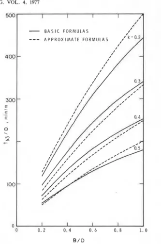
i B A S I C F O R M U L A S I IFIG. 2. Fire resistance of beams heated on three sides as a function of size and load.
.
mately by the expression:
Results obtained from this expression are given by the dashed lines in Fig. 1.
In Fig. 2 curves similar to those for beams heated on four sides are given for beams heated on three sides. For these beams the fire re- sistances, calculated from [3] and [4] and given by the solid lines in the figure, can be approxi- mated by the expression
/- Curves for columns heated on four sides are
shown in Fig. 3, where tc4/D (ratio fire resis-
I I I I tance to length of the smaller side of the
O
o 0 . 2 0 . 4 0. 6 0 . 8 1 . 0 column) is plotted as a function of D/B for
B / D various values of k. The solid lines give the
FIG. 1 . Fire resistance of beams heated on four fire resistance ~ a l ~ u l a t e d from and
-
B A S I C F O R M U L A S---
A P P R O X I M A T E F O R M U L A SFIG. 3. Fire resistance of columns heated on four sides as a function of size and load.
approximate formula
The curves in Figs. 1-3 indicate that for values of k in the range of about 0.2-0.5, cor- responding to safety factors in the range of 5-2, the formulas approximate reasonably well the calculated results. For safety factors higher than 5, which usually means that the member is substantially overdesigned, the approximate formulas considerably overestimate the fire re- sistance and are therefore no longer valid. It is possible, however, to derive for these cases the fire resistance of the member by using the relevant basic formulas, [I]-[I 51.
Comparison of Experimental and Theoretical Results
A large number of tests have been carried out on timber beams and columns. Almost all
tests on beams, however, were terminated be- fore failure occurred, and the remainder did not provide sufficient information to make a reliable comparison between experimental and theoretical fire resistances (Dorn and Egner 1960; Imaizumi 1962; Lawson et al. 1951; 0deen 1970). On the other hand, several measurements were made of various factors that determine the fire resistance, such as tem- peratures in the beam, rate of charring, and strength of the material. These measurements, and measurements on beams that had been exposed to fire in actual practice (Fox 1974), provided the basis for the development of the equations that have been presented.
More experimental information is available on the fire resistance of timber columns (Fackler 1961; Malhotra and Rogowski 1970; Stanke 1970: Stanke et al. 1973). As discussed earlier, the fire resistance of timber columns depends on a large number of factors such as timber species, moisture content, type of glue, slenderness of the column. but the most i m ~ o r - tant are column size and shape and the safety factor. In the approximate formula, [18], the influence of the three last-named factors have been taken into account by separate variable quantities D, B, and k. The influence of the other factors have been assumed to be rela- tively small, and average values have been used for the variables affected by them. These variables include the rate of charring
P,
for which the average value of 0.6 X m/min has been chosen. The influence of reduction of strength and stiffness of the uncharred wood and the faster loss of section at the corners have been taken into account by using a value for a of 0.80.A comparison between the fire resistances calculated from the design equation, [18], and those measured during a large number of tests (Fackler 1961 ; Malhotro and Rogowski 1970; Stanke 1970; Stanke et al. 1973) is made in Fig. 4. In this figure, all results of these tests on laminated columns are shown, with the ex- ception of those tests in which the load on the column was less than one half of the allowable load.
As shown in the derivation of the design formulas, for such loads these formulas sub- stantially overestimate the fire resistance and are therefore not valid. The results in Fig. 4
CAN. J. CIV. ENG. VOL. 4. 1977
E X P E R I M E N T A L F I R E R E S I S T A N C E , m i n
Fro. 4. Comparison between calculated and experimental fire resistances (not corrected for overdesign and column slenderness).
include those of tests with various safety fac- tors, wood species, moisture contents, types of glue, and column sizes, shapes, and slenderness ratios. Since the actual safety factor was not known precisely for each test, an average value of k = 0.33 has been used in the design for- mula. This value of k corresponds to a safety factor of 3, which is approximately equal to the safety factor customarily assumed in vari- ous fire resistance studies (Imaizumi 1962; Odeen 1970; Stanke 1970; Stanke et al. 1973). Tests on sawn timber have not been included. Their performance is considerably affected by the formation of shrinkage cracks (Stanke 1970) and therefore it is not possible to make a reliable prediction of their fire resistance.
It is seen in Fig. 4 that, although most pre- dictions err on the safe side, differences be- tween calculated and measured fire resistances of the order of 50% occur. The greater differ- ences, however, are for columns that were tested under a load less than the design load. It may be expected that in these cases the safety factor is higher than the factor 3 assumed in the design formula, so that in these cases
the predictions are conservative. If only the
tests in which the design load was applied are
considered, the agreement between calculated and experimental results becomes much better. There is still a systematic difference, how- ever, between calculated and experimental re- sults for the columns with higher fire resis- tances, but the differences are not large and are accountable. As discussed before, there are advantages to using only one formula instead of three to describe the fire resistance of col- umns of varying slenderness. Therefore a value of n = 2 was chosen in the basic equa- tion, [14], for the calculation of fire resistance, irrespective of the column slenderness, although
n = 1 would be more exact for short columns
and n = 3 for long columns. As a consequence, [14] tends to overestimate the fire resistance of long columns, and to underestimate that of short columns. The overestimation of calcu- lated fire resistances for longer columns, which in general are represented by the lower fire resistances in Fig. 4, is not clear. However, for shorter columns, represented by the higher fire resistances, the underestimation of fire resistance is pronounced.
Since slenderness of columns and overdesign have significant influence on fire resistance, the accuracy of the design formulas can be
E X P E R I M E N T A L F I R E R E S I S T A N C E , rnln
FIG. 5. Comparison between calculated and experimental fire resistances (overdesign and column slenderness are taken into account).
improved if the influence of these factors is taken into account in the formulas. A simple way of doing this is by including an empirical factor f in the calculated fire resistance for shorter columns or if the column is over- designed.
The following approximate formulas are suggested for the calculation of the fire resis- tance of timber beams and columns.
Beams Heated on Four Sides
Beams Heated o n Three Sides
Columns Heated o n Four Sides
The factor f depends on the load and for columns also on the effective length, as given in Table 1. If a load is applied that is lighter than the allowable load the fire resistance of a member increases. The higher fire resistance of a member that is overdesigned is expressed by a higher value of f. With respect to fire, a member may be regarded as overdesigned if it
TABLE 1. Values off Member type
Column Load (as %
of allowable load) Beam (LID) > 10 (LID) 1 10
is designed to resist extreme loads such as loads due to earthquake, wind, or snow. Be- cause the probability of occurrence of earth- quake or strong wind at the time of fire is very low, in the determination of the load for the time that the member is exposed to fire, the effects of earthquake and wind may be ne- glected. Loads due to snow have a higher probability of occurrence. It is not likely, how- ever, that the construction, e.g. roofs or other surfaces, will be subjected to the full design snow load-during exposure to fire. Because the magnitude of the load at the time of fire is determined by chance it cannot be predicted. It seems reasonable, however, to assume that the probability of occurrence of fire and at the
168 CAN. J. CIV. ENG. VOL, 4, 1977
same time a snow load greater than 50% of
-
1967. Brandversuche an brettschichtverleimtenu ~ ---.-- ~ . - ~ .-....-..
the design snow load is negligible. It is sug- Ho1ztr"em unter Biegebeanspmchung. Holz als Roh- und Werkstoff, 25 Jahrgang, Heft 8, pp. 308-320.
gested, to assume for fire FACKLER, J. P. 1961. Essais de rtsistance au feu. Centre that the snow load is 50% of the design snow Scientifique et Technique du Bstiment, Cahier 415.
. .
load. Fox, S. P. 1974. ~ e s i d u a l strength of fire-damaged lami-
In Fig. 5, the fire resistances calculated from nated bmms. For. Prod. J. 24(1), pp. 48-50.
[2l1 are with experimental results. HALL, beams. Timber Res. Dev. Assoc. Res. Rep. WT/RR/l, G. S. 1968. Fire resistance tests of laminated timber It is seen that some differences between calcu- High Wycombe, England.
lated and experimental results of the order of IMAIZUMI,K. 1962. Stability infireofprotectedandunpro-
35-40% remain, but if it is taken into con- tected glued laminated beams. Norw. Inst. Wood Work-
sideration that differences in the measured fire resistance between repeat tests of about 30% are not uncommon (Stanke 1970; Stanke et a1.
1973), the predicted fire resistances may be regarded as reasonably accurate.
Example
It might be useful to illustrate in an example the use of the approximate formulas for the calculation of the fire resistance of timber beams and columns. In this example a beam is considered that is exposed to fire on three sides. The breadth B of the beam is 0.25 m and its depth D is 0.75 m. The load on the beam may be assumed to be 75% of the allowable load.
According to 1201 the fire resistance of the beam is given by
According to Table 1, for a load of 75 % of the allowable load, f = 1 . l . Therefore, substi- tution of values into the formula gives
Thus the calculated fire resistance of the beam is 101 min.
Acknowledgement
The author wishes to thank Mr. J. E. Berndt for the programming of the equations. This paper is a contribution from the Division of Building Research, National Research Council of Canada and is published with the approval of the Director of the Division.
American Society for Testing and Materials. 1974. Stan- dard methods of fire tests of building construction and materials. ASTM E l 19-73.
DORN, H. and EGNER, K. 1960. Brandversuche an geleim- ten Holzbauteilen. Mitteilungen der Deutschen Gesellschaft fur Holzforschung, Heft 47.
1961. Brandproeven met gelamineerde houten bal- ken. Bouw, No. 50, pp. 13-15.
ing wood Technol., Meddelelse nr. 18, 14 p.
KNUDSON, R. M. and SCHNIEWIND, A. P. 1975. Perfor- mance of structural wood members exposed to fire. For. Prod. J. 25(2), pp. 23-32.
LAWSON, D. J., WEBSTER, C. T., and ASHTON, L . A. 1951. Fire endurance of timber beams and floors. Natl. Build. Studies, Bull. No. 13, H.M. Stationery Office, London, England.
LIE, T. 7 . 1972. Fire and buildings. Applied Science Pub. Ltd., London, England.
MALHOTRA, H. L. and ROGOWSKI, B. F. W. 1970. Fire- resistance of laminated timber columns. Min. Technol. Fire Offices' Comm. Joint Fire Res. Org. Symp. No. 3, Paper No. 3, H.M. Stationery Office, London, England. ODEEN, K. 1970. Fire resistance ofglued, laminated timber
structures. Min. Technol. Fire Offices' Comm. Joint Fire Res. Org. Symp. No. 3, Paper No. 2, H.M. Station- ery Office, London, England. pp. 7-15.
ROGOWSKI, B. F. W. 1970. Charring of timber in fire tests. Min. Technol. Fire Offices' Comm. Joint Fire Res. Org. Symp. No. 3, Paper No. 4, H.M. Stationery Office, London, England.
SCHAFFER, E. L. 1967. Charring rate of selected woods- transverse to grain. U.S. For. Serv. Res. Paper FPL 69, U.S. Dept. Agri., For. Prod. Lab., Madison, WI. STANKE, J. 1970. Ein Beitrag zur theoretischen Ermitt-
lung der Feuerwiderstandsdauer von einterligen, brett- schichtverleimten Stiitzen unter Druckbeanspruchung. VFDB-Zeitschrift, 19 Jahrgang, Heft 2, pp. 67-71. STANKE, J., KLEMENT, E., and RUDOLPHI, R. 1973. Das
Brandverhalten von Holzstutzen unter Druckbean- spruchung. BAM-Berichte Nr. 24, Bundesanstalt fiir Materialprufung, Berlin.
TENNING, K . 1970. Glued laminated timber beams: Fire tests and experience in practice. Min. Technol. Fire Offices' Comm. Joint Fire Res. Org. Symp. No. 3, Paper No. 1, H.M. Stationery Office, London, England. (Translated from Brandskydd, No. 4,1961 .)
Notation
A = area of cross section (m2)
b = breadth of uncharred part of member at the time of failure (larger side of column, smaller side of beam) (m)
B = breadth of member before exposure to fire (larger side of column, smaller side of beam) (m)
d = depth of uncharred part of member at the time of failure (smaller side of column, larger side of beam) (m)
I
I D = depth of member before exposure to fire
(smaller side of column, larger side of beam) (m)
E = modulus of elasticity (N/m2) f = factor (values given in Table 1)
k = ratio between applied load and ultimate load
L = effective length of column (m)
n = exponent in [14], taking into account the dependence of the critical depth of columns on column length
p = load (N/m2)
pa = applied load (N/m2) p' = buckling load (N/m2)
r = radius of gyration (m)
t,, = fire resistance of beams heated on three sides (min)
t,, = fire resistance of beams heated on four sides (min)
t,, = fire resistance of columns heated on four sides (min)
a = a factor that takes into account the reduc- tion of compressive strength (or modulus of elasticity) due to temperature rise in the uncharred part of column or beam
/I = rate of penetration of the charring (m/min) ~
a = stress (Nlmz)
a, = compressive strength of the wood before exposure to fire (N/m2)