Publisher’s version / Version de l'éditeur:
Vous avez des questions? Nous pouvons vous aider. Pour communiquer directement avec un auteur, consultez la première page de la revue dans laquelle son article a été publié afin de trouver ses coordonnées. Si vous n’arrivez pas à les repérer, communiquez avec nous à PublicationsArchive-ArchivesPublications@nrc-cnrc.gc.ca.
Questions? Contact the NRC Publications Archive team at
PublicationsArchive-ArchivesPublications@nrc-cnrc.gc.ca. If you wish to email the authors directly, please see the first page of the publication for their contact information.
https://publications-cnrc.canada.ca/fra/droits
L’accès à ce site Web et l’utilisation de son contenu sont assujettis aux conditions présentées dans le site LISEZ CES CONDITIONS ATTENTIVEMENT AVANT D’UTILISER CE SITE WEB.
Research Paper (National Research Council of Canada. Division of Building
Research); no. DBR-RP-561, 1973-05-01
READ THESE TERMS AND CONDITIONS CAREFULLY BEFORE USING THIS WEBSITE.
https://nrc-publications.canada.ca/eng/copyright
NRC Publications Archive Record / Notice des Archives des publications du CNRC :
https://nrc-publications.canada.ca/eng/view/object/?id=b90cba5a-9cc5-4083-bc08-d19fa13e2e3d https://publications-cnrc.canada.ca/fra/voir/objet/?id=b90cba5a-9cc5-4083-bc08-d19fa13e2e3d
NRC Publications Archive
Archives des publications du CNRC
This publication could be one of several versions: author’s original, accepted manuscript or the publisher’s version. / La version de cette publication peut être l’une des suivantes : la version prépublication de l’auteur, la version acceptée du manuscrit ou la version de l’éditeur.
For the publisher’s version, please access the DOI link below./ Pour consulter la version de l’éditeur, utilisez le lien DOI ci-dessous.
https://doi.org/10.4224/40001749
Access and use of this website and the material on it are subject to the Terms and Conditions set forth at
Penetration of fire partitions by plastic DWV pipe
Ser TH1 N211-2 3 i
3057
$ , &< 'I"" " &\i\ E"" '* no.561
NATIONAL RESEARCH COUNCIL OF CANADA'
INSEIL NATIONAL DE RECHERCHES DU CANADA
BLDG
Penetration of Fire Partitions
by
Plastic
D
WV
Pipe
byJ. H. McGuire
Reprinted from FIRE TECHNOLOGY Vol. 9, No. 1, February 1973
p. 5-14
Research Paper No. 561 of the Division of Building ~ e s e a r c h OTTAWA May 1973 Price 25 cents NRCC 13196 3 1809 001 98 21 87
PENETRATION DES INCENDIES EN CLOISON PAR VOIE D E TUYAUX DWV E N PLASTIQUE
SOMMAIRE
On a examine le risque de propagation du feu en travers d'un mur ou d'un plancher par suite de sa p6n6tration par voie de tuyaux DWV en plastique. On a d6couvert que le risque est trbs r6el dans le cas de plusieurs p6n6trations tuyau/plancher et de p6n6trations tuyau/mur dans le cas de diffhrentielles de pression adverses et aussi lorsque le systkme est pourvu d'6vents du c6t6 non expos6 du mur. Malgr6 ces d6couvertes' on estirne qu'il est possible d761aborer des systkmes DWV pour des 6difices, lesquels seraient constitu6s de tuyaux en plas- tique mais ne comporteraient pas le risque de propagation du feu en travers des cloisons. On n'examine pas d'autres aspects de la protection contre les incendies, tels le potentiel g6n6rateur de furn6e de certaines matikres plastiques.
FIRE TECHNOLOGY
Penetration of Fire Partitions
by
Plastic
D
WV
Pipe
J. H. McGUIRE, S F P E
Fire Research Section, Division of Building Research National Research Council of Canada
The hazard of fire propagation across a wall or floor has been found to be very real in the case of many pipe-floor penetrations and in the case of pipe-wall penetrations under adverse air pressure differentials and where the system on the unexposed side of the wall is vented.
F
IRE-RESISTIVE partitions must remain substantially imperforate, particularly when adverse air pressure differentials prevail, if they are to perform their function of containing fire. In establishing services in a building, however, penetration of partitions is almost inevitable. This paper reports the results of tests aimed a t investigating the circumstapces under which various plastic DWV (drain, waste, and vent) pipes can penetrate fire partitions without creating undue hazard of transmitting fire from one side of the partition to the other. The tests were particularly oriented to- ward high-rise building applications because they can involve the greatest adverse pressure differentials and hence the greatest risk of fire propagation across a partition. Such fire propagation also constitutes a greater potent,ial threat to life safety when it occurs in a high-rise rather than a low-rise building.In addition to the possible hazard of fire propagation across a partition, the use of certain plastic pipes could enhance the potential smoke, toxic gas, and corrosion problems in a building. These questions, however, are outside the scope of this paper.
C O N D I T I O N S T O B E R E P R E S E N T E D
As the issue under consideration concerned fire resistance, it was as- sumed a t the outset that the heating conditions should be based on the
Standard Methods of Fire Tests of Building Construction and Materials,
NFPA No. 251 (also ASTM E 119 and UL No. 263) fire-resistance furnace time-temperature curve. No NFPA fire-resistance test standard, however,
Copyright 1973 NATIONAL FIRE PROTECTION ASSOCIATION, 60 BATTERYMARCH ST., BOSTON, MASS. 02110 Printed in U.S.A.
6 Fire Technology
requires a test furnace to be operated a t a positive pressure differential. Where a pipe penetrating a partition is vented, the sign of the pressure differential could be critical -positive contributing to fire propagation and negative not contributing.
For many minutes during the early stages of a building fire, expansion of gases in the fire region can produce differentials that usually do not exceed 0.1 in. WG (water gage); thus, unfavorable pressure differentials of this magnitude can be expected in any building. When high buildings are considered during a Canadian winter, pressures of a t least this magnitude can be sustained continuously as a result of stack action created by building heating. During the normal use of the building, these pressure differentials appear largely across the exterior skin of the building. I t is only during a fire, when windows in the exterior skin are likely to be broken, that a large pressure differential can appear across a critical partition instead of across an exterior wall.
Tamural, in applying a computer t o the solution of the pressure pattern within a 20-story building with an interior-exterior temperature differential of 75" F , derived results that can be extended t o cover the conditions under discussion. For his hypothetical building, he showed that the floor area a t grade level was a t a pressure of 0.212 in. WG lower than that outside, while the shaft a t that level was a t a pressure of 0.048 in. WG lower still. If the ground floor area pressure and exterior pressure were equalized as a result of broken windows, the overall influence on the pattern of pressures and flows within the building would not be great. The shaft pressure would not change greatly, but the whole of the pressure difference between the exterior and the shaft would then appear across the shaft wall. I n the case cited, the pressure difference would be about 0.2 in. WG; for buildings of different heights, i t would be proportionally greater or smaller.
Such pressure differentials across a partition can sharply influence its fire-resistance time, particularly where openings are likely to develop.
It is thus desirable, when investigating the penetration of partitions by plastic pipes, to consider the effect of adverse positive pressure.*
The performance of pipes that penetrate partitions might be highly de- pendent on the building materials involved, and such a dependency could greatly increase the range of conditions to be investigated. The nature of the building materials, however, might be regarded as not very significant on the grounds that the material immediately adjacent to the pipe would generally be some packing material. The thickness of the partition might then be its most important feature.
Having made this assessment of the conditions to be represented, the relevance of previously published infomiation was considered.
*IS0 Recommendation R834, .Fire Resistance Tests of Structures, September 1968, suggests in paragraph 5.2.2.2 that, where the significance of a crack etc. is in doubt, a pressure difference of 0.06 & 0.02 in. W G should be sustained and a pad of cotton wool
Plastic Pipe
P R E V I O U S W O R K
The only fairly comprehensive, well-known study of the hazard as- sociated with the penetration of partitions by plastic pipes was carried out in Sweden in 1963 and reported in 1966.2 Of numerous tests on pipes of up to &in. diameter, only 8 performed satisfactorily for periods in excess of 60 min (up to a maximum of 110 min). I n each of these cases, the pipe was sleeved where it passed through the partition and for about 20 in. (50 cm) on either side. The temperatures prevailing in the fire chamber were ap- preciably lower than the time-temperature curve prescribed for an NFPA fire-resistance test, and no attempt was made to establish a definite positive pressure differential between the fire chamber and the unexposed region.
A Dutch report3 is more concerned with developing a test method as- sociated with the penetration of floors and ceilings by plastic pipes than with producing test results. A few test results are reported, but no conclusive pattern of performance was established.
As these two pieces of work did not cover the conditions currently of interest, with particular emphasis on high-rise buildings, further study was decided upon. I n the first instance, an investigation into the pene- tration of walls by horizontal plastic pipes was initiated.
E X P E R I M E N T A L P R O C E D U R E W A L L S A N D H O R I Z O N T A L P I P E S
Some exploratory testing of pipe-wall penetrations using an available small-scale, electric, fire-resistance furnace had to be discontinued because of arcing and general disturbance associated with the silicon carbide electric heating elements. Closer examination showed that products of combustion from a plastic sample were deposited on insulation associated with the elements and had provided unwanted conductive paths.
To avoid further problems of this nature, a two-chambered, gas-fired furnace was designed specifically for testing pipe-wall assemblies (Figures 1 and 2). Eight gas-fired burners were located in the outer chamber, and their products of combustion passed into the inner chamber under some pressure and thence to the flue. I t should be noted that the flue was directed downward to ensure that stack action contributed to, rather than dimin- ished, the positive pressure differential required in the test chamber. The test pipe was located on the axis of the inner chamber, and specimens repre- senting test walls were used to close the two ends of the chamber. Two pipe-wall penetrations were thus tested simultaneously during the course of any one furnace operation.
The wall samples used for each test were 18 in. by 18 in. by 4 in. and were fabricated of castable refractory with a density of 57 lb ft-3. The pipe passed through a circular opening 5 in. in diameter. For both 4-in. and 3-in. diameter pipes, the resulting annular space was packed with a soft asbestos material. Where 2-in. pipes were tested, a refractory annulus of
Fire Technology
Figure 1. General view of furnace.
%in. internal diameter was inserted in the opening and again the remaining space was packed with soft asbestos.
During the course of the tests, trouble was experienced in determining pressure; and it can only be said that the prevailing pressure differential ranged between 0.1 in. and 0.2 in. WG, generally being near the lower value a t the start of a test and the higher value towards the end. Earlier ex- ploratory tests had, in fact, indicated that the essential feature in creating unfavorable conditions was to establish a definite positive pressure to give
/ R E F R A C T O R Y F I R E B R I C K S
TEST W A L L
C H A M B E R
S O F T A S B E S T O S P A C K I N G
Plastic Pipe 9
a flow of hot gas through any opening that appeared. The magnitude of the pressure differential, within a range of 0.05 in. to 0.5 in. WG, did not appear to be of much significance.
For almost all of the experiments, both ends of the pipe were closed with a metal cap and tape to represent their leading to trapped fixtures. Ten-foot lengths of pipe were used, leaving about 3 f t projecting from each end of the furnace. Both ends of the pipe were supported by wire as illustrated in Figure 1.
Each test could be regarded as providing two results, a single pipe pene- trating test wall samples on two opposite faces of the furnace. For all but one of the tests (Test No. 8), one penetration was sleeved and the other was not. The sleeve material was 22-mil galvanized steel sheet, which was rolled and secured with wire a t the center and near each end to form a sleeve with an overlap of about 1 ?4 in.
During a test, it was usual for the unsleeved pipe to "fail" within about 30 min; this end of the pipe would then be removed and the resulting open- ing plugged with soft asbestos. The test was continued until either 2 hours had elapsed or until the other end "failed." A wall penetration was said to have "failed" when hot gases or flame issued freely around a pipe. The onset of these conditions was invariably quite rapid so that an accurate definition of the criteria was not called for. Except when a pipe melted and sheared off, failure was a result of progressive destruction of the top wall of the pipe out to the end of the sleeve or, in the case of the unsleeved pene- tration, to the boundary of the wall.
R E S U L T S
W A L L S A N D H O R I Z O N T A L P I P E S
Samples of the following pipes in 4-in., 3-in., and 2-in. diameters were tested:
1) PVC Type 2, Grade 1, DWV pipe; 2) ABS Type 1, Grade 2, DWV pipe;
3) Polyethylene, Type 1, Schedule 40, laboratory drainage pipe; 4) Polyethylene, Type 3, Schedule 40, laboratory drainage pipe; 5) Polypropylene, Type 1, Schedule 40, laboratory drainage pipe; and 6) Fire-retardant polypropylene laboratory drainage pipe.
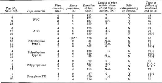
Table 1 lists the principal results of this portion of the test program. The dimension referred to in Column 4 is the amount by which the sleeve projected on each side of the wall. The total length of the sleeve was, therefore, approximately twice the dimension specified in Column 4 plus 4 in. - the thickness of the test wall. Test No. 28 was the exception to this rule for the sleeve projections within and outside the furnace were different
- 9 in. and 18 in. respectively.
The dimension referred to in column 6 as "length of pipe within sleeve a t test termination" relates to the dimension a t the top of the pipe. The end of the pipe a t this time during the test did not generally represent
Fire Technology
TABLE 1. Results of Wall-Horizontal Pipe Tests
Length of pipe Time of Pipe Sleeve Duration within sleeve Self- failure of Test No. diameter, projection, of lesl, at lest termi- extinguishing unsleeved N C R Ref. Pipe material (in.) ( i n . ) ( m i n ) nation, (in.) on removal end (min)
1 4 9 120 7 Y 48 7 3 9 120 8 Y 45 9 P V C 3 6 120 5 % Y 55 23 2 4 120 3 Y 45 6 4 9 120 4 N 23 12 ABS 3 6 120 3 K N 29 16 2 6 120 5 N 36 % 28 4 1.3.. 126 0 N 20 10 Polyethylene 4 9 3 1 N.A. N 19 11 type 1 3 6 4 1 N.A. N 17 19 2 6 102 0 N 18% 4 Polyethylene 4 9 120 % 13 t y p e 3 3 6 120 1 2 1 2 4 89 N.A. Polypropylene Proxylene FR 0 2 % 0 N.A. N 19 N.A.; N N.A. N 19 -- - - = no information available
N.A. = not applicable. Pipe sheared away, leaving some i n t h e sleeve. N.A.* = not applicable. Both ends were sleeved i n test No. 8.
* * = Nine In. w i t h ~ n t h e furnace. I n addition, this particular sleeve was secured by wire In four places.
a vertical face; the rate of destruction was usually less toward the bottom of the pipe.
No record of sleeve temperatures is presented in Table 1. At the cooler end of the sleeve, they ranged as high as 540" F ; and near the cooler face of the test wall specimen, one sleeve registered a temperature of 1100" F. I n general, therefore, it should be assumed that combustible material placed in contact with the sleeves would have been in extreme danger of igniting. The test results reported so far refer only to the representation of pipes leading to trapped fixtures on the unexposed sides of partitions. A test was also carried out on a test pipe, the ends of which were left open. I n other respects, test conditions were the same. The test pipe chosen was 4-in. PVC, as it had given the best results up to that time from the fire propagation point of view and because it was the only pipe in which an in- tumescent effect had blocked the pipe to an appreciable extent. The sleeve projection was 9 in. as it was for all but one of the previous 4-in. pipe tests. During the first few minutes of test, it was possible to look through the length of pipe along it.s axis. After 5 minutes, deformation a t the top center could be seen; and a t 6% min, smoke began to flow into the pipe and visibility fell to little more than 1 in. Shortly afterwards, the flow termi- nated a t both ends, indicating that seals had been created. After 13 min, the unsleeved end began issuing smoke again; and a t 16 min, the sleeved end followed suit. After 18 min, the unsleeved end began deforming; and a t 20% min, it fell away from the furnace. It was then seen that the pipe had been destroyed out to the face of the wall.
After 35 min, the sleeved end of the pipe began to deform; and after 40 min, a gap appeared between the sleeve and the pipe. At this stage, the
Plastic Pipe 11
test could have been terminated, but the furnace was kept operating for an additional 7 min. After 45 min, a red hot region (probably the furnace) was visible to observers looking down the axis of the pipe. The furnace was shut off after 47 min, and a minute later the pipe in the region of the sleeve ignited and fell out almost immediately. Examination of the remains showed that the pipe had been destroyed right out to the edge of the sleeve.
E X P E R I M E N T A L P R O C E D U R E F L O O R S A N D V E R T I C A L P I P E S
The furnace could not conveniently be turned on its side to permit the testing of vertical pipes penetrating floors. Rather than construct a new furnace, this phase of the work was accomplished by setting up a mock section of the ceiling in the laboratory and carrying out ad hoc tests.
It is desirable to represent a substantial pressure differential across the penetrated partition, and in the case of the pipe-wall tests using the furnace, adequate positive pressure differentials were maintained. This re- quirement was not satisfied by the ad hoc conditions established during the pipe-floor tests described here. Thus one of these test results indicating poor performance can be regarded as valid, but the same cannot be said for a test result indicating satisfactory performance.
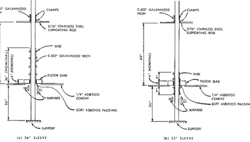
The two test arrangements investigated are illustrated in Figure 3 and differ only with regard to the sleeving of the pipe where it penetrated the "floor slab." I n the one case (a), the sleeve projected above the "floor slab," and in the other case (b), a shorter sleeve projected symmetrically above and below.
The test pipes were 10 f t long and were supported a t the base and about 2 f t below the top. The latter support consisted of a rod penetrating the
IRON 3 / l C STAlNlESS STEEL S!IPPORTING ROD 0.022" GALVANIZED'IRON
F-
wlK FLOOR SLAB IN' ASBESios CEMENTI
SOFT ASCSTOSL
SUPPOR, ( a 1 3 6 " SLEEVE 8 PACKINGI I
\3/16" STAINLESS STEEL SUPPORTING ROD 1/4" ASBESTOS CEMENT WFl ASUESTOS BURNERS ' L S U P P O R T ( b ) 2 2 " SLEEVE PACKING12 Fire Technology
pipe immediately beneath a second sleeved portion of the pipe. Such an arrangement was merely intended to constitute a reliable support and obviously was not representative of typical practice.
The test "floor slab" consisted of concrete blocks about 3% in. thick (4 in. nominal) with a density of approximately 95 lb ft-3. An annular space of a little over half an inch between the pipe and the concrete slab was packed with soft asbestos.
The burners were multiple flamelet gas rings; and as illustrated in Figure 3, they were mounted sideways on either side of the pipe 2 in. away from it and approximately 2 in. below the bottom of the sleeve. The fuel was natural gas with a calorific value of approximately 1020 Btu ft-3, and it was supplied a t a rate of 3% cfm. Lighting of the burners constituted the start of the test.
R E S U L T S
F L O O R S A N D V E R T I C A L P I P E S
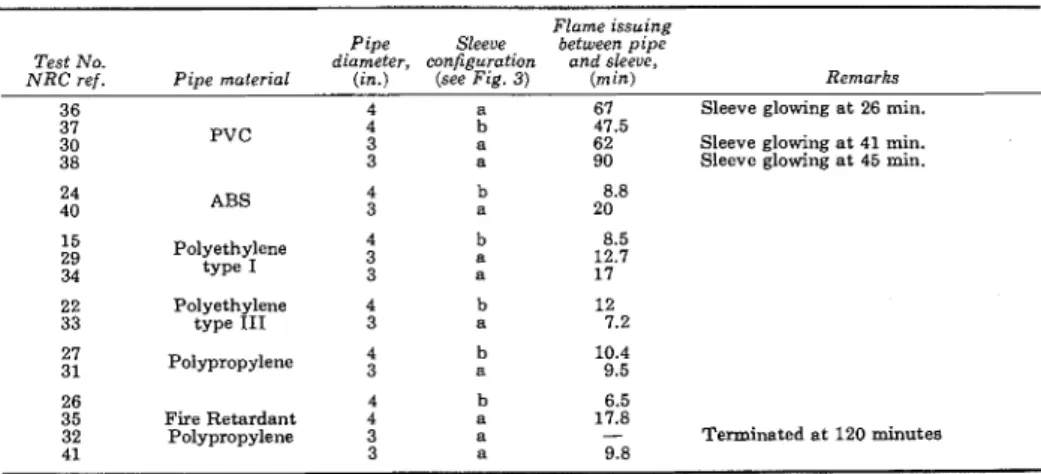
The pipes tested were as listed for the previous series of tests except that no 2-in. diameter samples were included. Table 2 summarizes the results of the tests. Not recorded is the fact that the pipe in the vicinity of the burners was penetrated within 6 rnin of the start of each test, as evi- denced by the emission of smoke from the top of the pipe.
I t was assumed that the issuance of flame between the pipe and the top of the sleeve could be regarded as evidence of extreme hazard, and it will be seen that this occurred within 20 rnin in all the tests except those
involving PVC pipes and one with a 3-in. fire-retardant polypropylene pipe. Three of the PVC pipe tests withstood more than one hour of exposure before flame issued between the pipe and the top of the sleeve. I n each of these cases, however, portions of the sleeve up to 4 in. or more above the "floor slab" glowed visibly within the first 45 min of test. Such a condition
TABLE 2. Results of Floors-Vertical Pipe Tests Flame issuing Pipe Sleeue between pipe Test No. diameter, configuration and sleeue,
N R C r e f . P i ~ e material ( i n . ) (see Fie. 3 ) ( m i n ) Remarks
36 4 a 67 Sleeve glowing at 26 rnin. 37
PVC 4 b 47.5
30 3 a 62 Sleeve glowing a t 41 min. 38 3 a 90 Sleeve glowing a t 45 min.
ABS 15 Polyethylene 4 b 8.5 29 t y p e 1 3 a 12.7 34 3 a 17 22 Polyethylene 4 b 12 33 t y p e I11 3 a 7.2 27 Polypropylene b 10.4 31 a 9.5 26 4 b 6.5 35 Fire Retardant 4 a 17.8
32 Polypropylene 3 a - Terminated at 120 minutes
Plastic Pipe 13
arises only when the pipe has been destroyed and has disappeared from that particular region and when very hot gases are flowing freely through it to effect adequate heat transfer to the glowing metal.
The first 3-in. diameter fire-retardant polypropylene pipe remained in place for 2 hours, a t which time the test was terminated. On removing the 36-in. sleeve, it was found that the top 5 in. of the pipe within the sleeve were intact and that melting and coalescing had produced a cone below that sealed the pipe. Unfortunately, this test result cannot be taken as representative of the behavior of this pipe, for a repeat test resulted in flame issuing above the top of the sleeve within 10 min.
D I S C U S S I O N O F R E S U L T S
Discussing first the pipe-wall series of tests.
. .
the result of the test with the open-ended pipe suggests that, where appreciable adverse pressure differentials are involved, it is unlikely that the integrity of a fire partition penetrated by a horizontal plastic DWV pipe can be maintained by the use of a short sleeve. The length of sleeve required to maintain integrity, which might prove practical for small diameter pipe, has not been in- vestigated.When a pipe is closed (i.e., by a trapped fixture on the side not exposed to fire), the test results indicate that integrity can be maintained for the periods listed. As suggested previously, the nature of the wall is probably not important, provided it keeps in place the soft asbestos packing that should normally be around the pipe. I t is reasonable, therefore, to expect the closed pipe to perform satisfactorily with thicker walls of other materials.
Preliminary experiments and a consideration of the pressure effects in- volved also suggest that the performances tabulated would not be greatly dependent on the magnitude of the pressure differential involved within the range 0.05 in. to 0.5 in. WG.
I n many constructions, fire resistance times of 2 hours are required, and several of the pipe-sleeve combinations tested maintained their in- tegrity for this period. Where a combination did not prove satisfactory, a longer sleeve would be required. I n several cases it is, in fact, apparent that an additional inch or so of sleeve would have extended the time t o 2 hours.
The results of the second test series concerning the penetration of floors by vertical pipes were not encouraging. Except for one anomalous result, performance during the first hour was judged unsatisfactory either because flame issued between the pipe and the sleeve or because a portion of the sleeve above the "floor slab" glowed red hot a t some time. The anomalous case resulted from plugging of the pipe; and during an exact repeat of this particular test, flame issued between the pipe and the sleeve in just under 10 min. I n the case of the PVC pipes, the simple expedient of insulating the sleeve might be worth investigating as a means of giving satisfactory
14 Fire Technology
performance for one hour. Adequate insulation would eliminate the hazard associated with the glowing sleeve, but it might also accelerate the destruc- tion of the pipe higher up.
C O N C L U S I O N S
The penetration of floors and walls by plastic DWV pipe of the sizes and types examined presents risk of fire propagation under various conditions. The hazard exists for almost all penetrations of floors; and in the case of walls, it arises when adverse pressure differentials prevail and when the pipe on the unexposed side of the wall leads to a vented system. By careful consideration of the pattern of pressure differentials likely to prevail within a building, it is possible to devise largely plastic DWV pipe systems for buildings that will not give rise to undue hazard of fire propagation across fire partitions. Such DWV pipe systems might well involve com- binations of metal and plastic pipe.
It should be borne in mind that the scope of this paper has been confined to propagation of fire across partitions. Other factors could enter into fire protection considerations, among them being the smoke generating and corrosive potentialities of certain plastics.
Another aspect to be noted concerning the test work reported is that not all metal DWV systems would react favorably if subjected to the test con- ditions described. If penetration of the pipe occurred in the fire region, a positive pressure differential and a vented system could give rise to a high metal temperature beyond the penetrated partition as occurred with the PVC pipes penetrating the floors (Tests 30, 36, and 38). With certain modern jointing concepts, penetration of a metal pipe would be quite likely in the event of fire.
R E F E R E N C E S
1 Tamura, G. T., "Computer Analysis of Smoke Movement in Tall Buildings,"
ASHRAE Transactions, Vol. 7 5 , Part 11, 1969, pp. 81-93.
2 Fire Tests with Plastic Tubes Carried out a t the Research Station in Studsvik, Spring 1963, Report 18:1966.
van Sante, F. J., "Results of Fire Tests on Plastic Pipes and Sheets for Covering Walls and Ceilings," Foundation Ratiobouw, Holland, 1968.
This publication is being distributed by the Division of Building Research of the National Research Council of Canada. I t should not be reproduced in whole or in part without permission of the original publisher. The Division would be glad to be of assistance in obtaining such permission. Publications of the Division may be obtained by mailing the appropriate remittance (a Bank, Express, or Post Office Money Order, or a cheque, made payable to the Receiver General of Canada, credit NRC) to the National Research Council of Canada, Ottawa. KIA 0R6. Stamps are not ac- ceptable.
A list of all publications of the Division is available and may
be obtained from the Publications Section, Division of Build- ing Research, National Research Council of Canada, Ottawa.