Compact ultrafast frequency
combs
Thesis presented to the Faculty of Science for the degree of
Doctor of Science
Sargis Hakobyan
M. Sc. in Physics
Accepted on 29.11.2017 by the jury:
Prof. Thomas S¨
udmeyer Director
Prof. Eric Cormier
Examiner
Dr. St´
ephane Schilt
Examiner
Dr. Bojan Resan
Examiner
Dr. Valentin Wittwer
Examiner
Faculté des Sciences Secrétariat-décanat de Faculté Rue Emile-Argand 11 2000 Neuchâtel – Suisse Tél : + 41 (0)32 718 21 00 E-mail : [email protected]
IMPRIMATUR POUR THESE DE DOCTORAT
La Faculté des sciences de l'Université de Neuchâtel
autorise l'impression de la présente thèse soutenue par
Monsieur Sargis HAKOBYAN
Titre:
“Compact Ultrafast Frequency Combs”
sur le rapport des membres du jury composé comme suit:
• Prof. Thomas Südmeyer, directeur de thèse, Université de Neuchâtel, Suisse
• Dr Stéphane Schilt, Université de Neuchâtel, Suisse
• Prof. Eric Cormier, Université de Bordeaux, CELIA, France
• Dr Bojan Resan, Fachhochschule Nordwestschweiz, Suisse
• Dr Valentin Wittwer, Université de Neuchâtel, Suisse
Keywords - Mot-cl´
es
Keywords
Femtosecond laser, modelocked laser, diode-pumped solid-state laser (DPSSL), optical frequency comb, carrier envelope offset (CEO), self-referencing, phase stabilization, frequency noise, phase noise, opto-optical modulation (OOM), waveguide laser.
Mots-cl´
es
Laser femtoseconde, laser `a verrouillage de modes, laser `a corps solide pomp´e par diode, peigne de fr´equence optique, d´ecalage de fr´equence entre porteuse et enveloppe, auto-r´ef´erencement, stabilisation de phase, bruit de fr´equence, bruit de phase, modulation opto-optique (OOM), laser `a guide d’onde
Acronyms
AC Alternating current
AOFS Acousto-optic frequency shifter
AOM Acousto-optic modulator
CEO Carrier-envelope offset
CW Continuous wave
DBR Distributed Bragg reflector
DC Direct current
DPSSL Diode-pumped solid-state laser
EOM Electro-optic modulator
FN-PSD Frequency-noise power spectral density
FWHM Full-width half-maximum
HR Highly reflective
HVA High voltage amplifier
OC Output coupler
OOM Opto-optical modulator
PBS Polarizing beam splitter
PD Photodiode
PI Proportional integral
PID Proportional integral derivative
PM Polarization maintaining
PPLN Periodically polled lithium niobate
PZT Piezoelectric transducer
RBW Resolution bandwidth
RF Radio frequency
RIN Relative intensity noise
SC Supercontinuum
SESAM Semiconductor saturable absorber mirror
SHG Second harmonic generation
SM Single mode
SNR Signal-to-noise ratio
ULE Ultra low expansion
VECSEL Vertical External-Cavity Surface-Emitting Laser
VHG Volume holographic grating
Abstract
Optical frequency combs provide a direct and phase-coherent link between the optical spectral region of the electromagnetic spectrum (i.e., hundreds of THz frequencies) and the radio-frequency domain (MHz-GHz frequencies). As a re-sult, they constitute a unique and powerful tool for various applications such as broadband high-resolution molecular spectroscopy, optical metrology, astro-physics, optical clocks, fundamental science and many other fields of research. Frequency combs with a high repetition rate are of particular interest for appli-cations that can benefit from a high power per comb mode and a lower spectral density of comb modes, which makes the selection and filtering of a single optical line easier, and increases the signal-to-noise ratio in sensitive measurements.
Modelocked diode-pumped solid-state lasers (DPSSLs) are a perfect solution to generate high-power high repetition rate frequency combs. In this thesis, a 1-GHz comb based on a 1-µm DPSSL has been developed, with multi-watt output power and sub-100 fs pulse durations. This laser is an important step towards the development of compact cost-efficient frequency combs since it is pumped by a low-cost highly multimode pump laser diode. The optical spec-trum of the laser has been fully stabilized by phase-locking both the repetition rate frequency to a radio-frequency (RF) reference signal by means of a piezo-electrical transducer controlling the cavity length of the laser, and the carrier-envelope offset (CEO) frequency using the traditional method of feedback to the pump current. This was achieved using a home-made high-bandwidth current
modulator for fast control of the pump power, as CEO stabilization is particu-larly challenging in high-repetition rate combs and requires a large stabilization bandwidth to compensate for the generally larger CEO frequency noise.
A detailed study of the noise properties of the comb is presented, enabling the identification of the dominant noise sources and their subsequent partial reduc-tion. For instance, the limitation in the frequency noise of the comb lines arising at low Fourier frequencies from the noise floor of the RF reference signal used in the repetition rate stabilization was circumvented by locking a comb line to an optical reference, namely an ultra-stable Hz-level continuous-wave laser. As a result, a GHz frequency comb with ∼150-kHz comb mode linewidth was ob-tained with 2.1 W of average output power from the oscillator. The standard CEO stabilization method by feedback to the pump power is typically limited in bandwidth by the laser cavity dynamics, becoming a significant limiting factor in high-repetition rate combs. To overcome this limitation, the first opto-optical modulation (OOM) of a semiconductor saturable absorber mirror (SESAM) in a GHz DPSSL comb is reported in this thesis. With this SESAM-OOM, the stabilization bandwidth of the Yb:CALGO DPSSL was twice as large than the traditional gain modulation.
Another highly promising technology for GHz combs are waveguide lasers. As a first step towards such systems, Yb-doped waveguide lasers have been studied in CW and Q-switched operations. Waveguide lasers are one of the most attractive systems for fully integrated chip-based pulsed lasers. A highly-efficient Yb:YAG channel waveguide laser was demonstrated in this work, which can deliver Q-switched pulses with µJ pulse energies and an output power of up to 5.6 W. This achievement was made possible by recent progresses in fs-laser-written waveguide fabrication at Hamburg University and SESAM growth techniques at ETH Zurich with advanced structural designs. These lasers are very promising systems for various applications such as a seed source for nonlinear processes, Lidar systems, and micro-machining.
R´
esum´
e
Les peignes de fr´equences optiques fournissent un lien direct et coh´erent entre les domaines optiques (fr´equence de quelques centaines de THz) et micro-ondes (fr´equence dans les MHz ou GHz) du spectre ´electromagn´etique. Ils constituent un outil unique et puissant pour de nombreuses applications telles que la spectro-scopie mol´eculaire `a haute-r´esolution et `a large spectre, la m´etrologie optique, l’astrophysique, les horloges atomiques, la physique fondamentale et de nom-breux autres domaines de recherche. Les peignes de fr´equence avec un haut taux de r´ep´etition sont d’un int´ert particulier pour les applications pouvant b´en´eficier d’une puissance modale ´elev´ee et d’une faible densit´e de modes, qui facilite la s´election et le filtrage des modes individuels et augmente le rapport signal sur bruit dans des mesures sensibles.
Les lasers `a verrouillage de mode `a corps solide pomp´es par diode repr´esentent une approche avantageuse pour la r´ealisation de peignes de fr´equence de haute puissance et `a taux de r´ep´etition ´elev´e. Dans cette th`ese, un peigne avec un taux de r´ep´etition de 1 GHz a ´et´e d´evelopp´e `a partir d’un laser `a verrouillage de mode ´emettant `a une longueur d’onde de 1 µm. Le laser ´emet plus de 2 W de puissance moyenne dans des impulsions inf´erieures `a 100 fs. Ce laser repr´esente une ´etape importante vers la r´ealisation de peignes de fr´equence compacts et ´economiquement avantageux puisqu’il est pomp´e par une diode laser multimode de bas coˆut. Le spectre du laser a ´et´e enti`erement stabilis´e par le verrouillage en phase simultan´e du taux de r´ep´etition sur une
r´ef´erence radiofr´equence (RF) `a l’aide d’un ´el´ement pi´ezo-´electrique contrˆolant la longueur de la cavit´e, et du d´ecalage de fr´equence entre porteuse et enveloppe (carrier-envelope offset - CEO - en anglais) par la m´ethode traditionnelle de r´etroaction sur le courant de la diode de pompe. Cela a ´et´e r´ealis´e `a l’aide d’une ´electronique de modulation sp´ecifiquement d´evelopp´ee pour atteindre une haute bande passante de modulation qui est requise pour r´eduire le bruit g´en´eralement ´elev´e du battement CEO dans les lasers `a haut taux de r´ep´etition. Une analyse d´etaill´ee des propri´et´es de bruit du peigne est pr´esent´ee, qui a permis d’identifier les sources de bruit dominantes et de r´eduire leur impact. Ainsi, la limitation apparaissant `a basses fr´equences de Fourier dans le bruit de fr´equence d’une raie optique, qui provient du plancher de bruit de la r´ef´erence RF utilis´ee dans la sta-bilisation du taux de r´ep´etition, a ´et´e repouss´ee en stabilisant une raie optique du peigne sur une r´ef´erence optique. La r´ef´erence optique est un laser ultra-stable avec une largeur de raie de quelques hertz. Ainsi, un peigne de fr´equence avec un taux de r´ep´etition de 1 GHz, une puissance moyenne de 2.1 W et une largeur des raies optiques d’env. 150 kHz a ´et´e d´emontr´e. La m´ethode tradi-tionnelle de stabilisation du battement CEO par r´etroaction sur le courant de la diode de pompe est limit´ee en termes de bande passante par la dynamique de la cavit´e laser. Cela constitue une limitation majeure dans les peignes de fr´equence `a haut taux de r´ep´etition. Pour repousser cette limite, la premi`ere stabilisation du battement CEO dans un peigne de fr´equence avec un taux de r´ep´etition dans la gamme du GHz par modulation opto-optique (OOM) d’un miroir saturable est pr´esent´ee dans cette th`ese. Avec cette m´ethode, la bande passante de stabilisation du laser Yb:CALGO a ´et´e augment´ee d’un facteur 2 par rapport `a l’approche traditionnelle utilisant une modulation du gain.
Une autre technologie attractive pour la r´ealisation de peignes de fr´equence GHz sont les lasers `a guide d’onde. Comme premier pas dans cette direction, des lasers `a guide d’onde dop´es `a l’ytterbium ont ´et´e ´etudi´es en r´egime d’´emission continue et en mode d´eclench´e (Q-switched). Les lasers `a guide d’onde
constituent l’une des technologies les plus prometteuses pour la r´ealisation de lasers impulsionnels int´egr´es. Un laser `a guide d’onde Yb:YAG de haute efficacit´e est d´emontr´e dans ce travail, d´elivrant des impulsions en mode d´eclench´e avec une ´energie de plusieurs µJ par impulsion et une puissance moyenne de 5.6 W. Ces performances ont ´et´e rendues possibles par les r´ecents progr`es r´ealis´es dans les techniques de gravure de guides d’onde par lasers femtosecondes d´evelopp´ees `
a l’universit´e de Hambourg et dans la croissance de miroirs saturables `a semi-conducteurs `a l’ETH Z¨urich. Les lasers d´evelopp´es constituent une source attrac-tive pour de nombreuses applications telles que pour des processus non-lin´eaires, des lidars, ou pour le micro-usinage.
Contents
1 Introduction and motivation 1
1.1 Lasers . . . 3
1.1.1 Continuous wave lasers . . . 3
1.1.2 Modelocked lasers . . . 7
1.2 Frequency combs . . . 9
1.2.1 Carrier Envelope Offset frequency detection . . . 11
1.3 Stabilization of frequency combs . . . 13
1.4 Outline of the thesis . . . 14
2 High-power Yb:YAG waveguide lasers 17 2.1 Introduction . . . 17
2.2 Dielectric waveguide fabrication methods . . . 18
2.2.1 Ion-exchange . . . 18
2.2.2 Liquid-phase epitaxy . . . 19
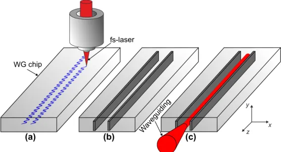
2.2.3 Femtosecond laser inscription . . . 20
2.3.1 Fabrication . . . 23
2.3.2 Experimental setup . . . 24
2.3.3 Laser results . . . 27
2.3.4 Conclusion . . . 31
3 GHz repetition rate Yb:CALGO frequency comb 33 3.1 Introduction . . . 33
3.2 1-GHz Yb:CALGO modelocked laser . . . 35
3.2.1 Design . . . 35
3.2.2 Laser performance . . . 39
3.3 CEO frequency detection . . . 40
3.4 Full stabilization of the frequency comb . . . 44
3.4.1 Static and dynamic comb control . . . 44
3.4.2 Stabilization schemes . . . 46
3.5 Characterization of the fully stabilized comb . . . 50
3.5.1 Frequency noise of the phase-locked comb parameters . . 50
3.5.2 CEO noise source analysis . . . 53
3.5.3 Frequency stability . . . 55
3.5.4 Characterization of an optical comb mode . . . 56
3.6 Conclusion . . . 61
4 GHz comb stabilization to an optical reference 65 4.1 Motivation . . . 65
Contents
4.2 Further investigation on frepnoise . . . 70
4.3 Comb stabilization to an optical reference . . . 73 4.4 Conclusion . . . 77
5 Opto-optical stabilization of fCEO 79
5.1 Introduction . . . 79
5.2 OOM-SESAM stabilization of fCEO in the 1-GHz Yb:CALGO laser 82
5.2.1 Experimental setup . . . 82 5.2.2 Stabilization results . . . 88 5.2.3 Conclusion . . . 91
6 Conclusion and outcomes 93
Bibliography 97
Curriculum Vitae 111
List of Figures
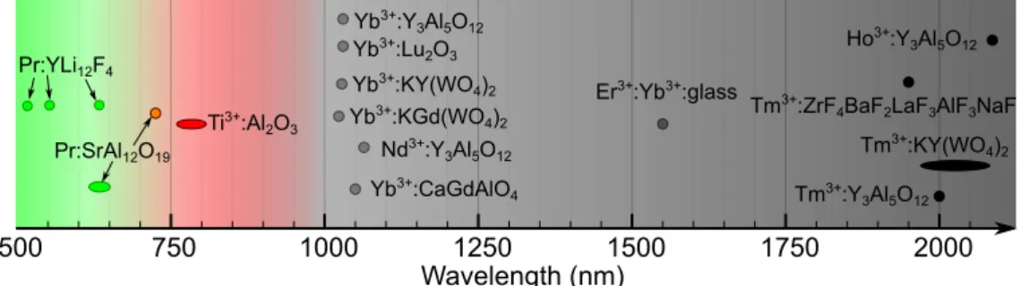
1.1 Fabry-Perot cavity, basic sechema of a laser . . . 3 1.2 Overview of the center emission wavelengths of some commonly
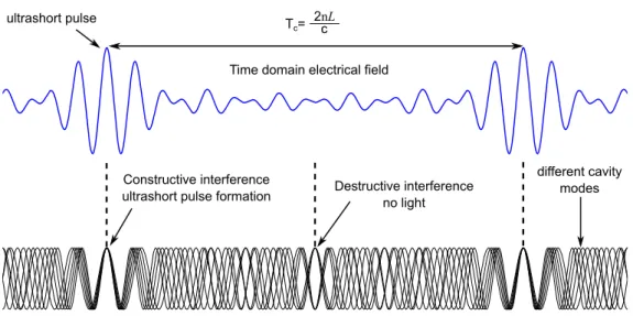
used laser gain crystals or glasses. . . 5 1.3 Cavity mode interference resulting in pulse formation in the time
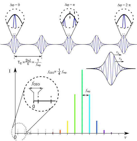
domain. . . 8 1.4 Time domain representation (top) and corresponding optical
spec-trum (bottom) of a modelocked laser frequency comb. In this par-ticular example, the carrier-envelope phase ∆ϕ changes by π/2 from pulse to pulse, resulting in a CEO frequency of one fourth of the repetition rate. . . 10 1.5 Measurement principle of the self-referenced f -to-2f
interferome-try, method for CEO frequency detection, showing the resulting generated beat signals at fCEOand frep-fCEO(formulas highlighted
in red and blue, respectively). . . 12
2.1 The main steps of the fabrication process of glass integrated chan-nel waveguides by ion-exchange. . . 19 2.2 Images of a waveguide fabricated by liquid-phase epitaxy. . . 20 2.3 Femtosecond laser inscription of a waveguide. . . 22
2.4 Schematic of the fs-laser writing mechanism. . . 24
2.5 Experimental setup of the CW and Q-switched Yb:YAG
waveg-uide lasers. . . 25 2.6 Picture of the waveguide laser in CW operation. . . 26 2.7 Output power (Pout) versus pump power (Ppump) for the CW laser
configuration. . . 28 2.8 (a,b) Average output power Pavand pulse energy Epversus pump
power (Ppump) for the Q-switched laser configuration. (c,d)
Op-tical spectra . . . 29 2.9 Single Q-switched pulse and Q-switched pulse train . . . 30 2.10 Pulse duration (τp) and repetition rate (frep) of the WG laser
versus pump power (Ppump) . . . 30
2.11 Overview of the reported results on Q-switched, Q-switch mode-locked and modemode-locked channel waveguide lasers. . . 32
3.1 a) Pout and Voltage drop vs the pump current Ipump of the diode
array, b) optical spectrum and M2 measurement of the diode array 36 3.2 Scheme of the Yb:CALGO GHz laser . . . 37 3.3 a) Picture of the overall Yb:CALGO laser cavity, b) Zoom on the
SESAM mounted onto the PZT. . . 38
3.4 a) Average output power vs pump power for CW and modelocked
(ML) operations. b) Optical spectrum of the laser in ML opera-tion. c) Normalized radio-frequency (RF) spectrum of the laser in ML operation. d) Autocorrelation (AC) trace of an optical pulse of the laser (blue trace) with a sech2 fit (dashed red line). . . 39
List of Figures
3.5 Overall scheme of the fully-stabilized Yb:CALGO GHz frequency comb. . . 41 3.6 Full octave-spanning SC spectrum measured at the output of the
PCF. . . 42 3.7 f -to-2f interferometer for fCEO detection. . . 43
3.8 Radio frequency (RF) spectrum of the signal at the output of the f -to-2f interferometer . . . 43 3.9 Amplitude and phase transfer functions of the frep, fCEO, and of
pump optical power for pump current modulation, insets: static tuning curves of frep and fCEO . . . 45
3.10 Stabilization scheme of frepand fCEO. . . 47
3.11 Picture of the RC filter. . . 48 3.12 Comparison of the RIN of the pump diode measured without and
with the RC filter placed between the high current source and the pump diode. . . 49 3.13 FN-PSD pf the fCEO and frep free running and fully-stabilized
GHz comb . . . 51 3.14 FN-PSD pf the fCEO and frep free running and fully-stabilized
GHz comb with mechanical damping of the laser breadboard and a derivative filter added to the repetition rate feedback loop . . . 52 3.15 a) FN-PSD measured for the free-running fCEO (yellow)
com-pared with the contributions of the current noise of the pump diode driver (red) and of the pump RIN, b) Comparison of the RIN of the pump diode measured with the water cooling chiller on and off. . . 54
3.16 Frequency stability of the fully-stabilized GHz comb: overlapped Allan deviation of fCEO (a) and relative (overlapped) Allan
devi-ation of frep (b). . . 55
3.17 Schematic principle of the measurement setup implemented to characterize one optical line of the GHz comb with respect to an ultrastable laser at 1.56 µm . . . 57 3.18 a) Comparison of the FN-PSD of the repetition rate assessed from
the direct measurement of frep in the RF domain and from the
optical CEO-free virtual beat fvirt.beat2CEO-free and of the reference syn-thesizer up-scaled by N2. b) FN-PSD of an optical mode of the fully-stabilized GHz comb, c) FWHM linewidth of the optical comb line calculated from the FN-PSD as a function of the low cut-off frequency . . . 60
4.1 Noise of Rohde & Schwarz SMF100. . . 66 4.2 Comparison of Rohde & Schwarz SMF100 up-scaled noise and
optical reference noise. . . 67 4.3 Experimental setup for the measurement of the fiber link noise.
Yellow and black lines represent singlemode fibers and electrical connections respectively, PD: photodiode; AOM: acousto optic modulator. . . 68 4.4 Noise of the fiber link. . . 69 4.5 Transfer functions of the mirror mounts with acoustic vibrations. 71 4.6 FN-PSD of the repetition rate optimization. . . 72 4.7 Schematic of the stabilization of the GHz comb to an optical
List of Figures
4.8 FN-PSD of the optical comb line of the GHz comb when stabilized with RF and optical reference. . . 75 4.9 FN-PSD of the repetition rate of the GHz comb when stabilized
with RF and optical reference. . . 77
5.1 FN-PSD of fCEO for the 1-GHz and 96-MHz Yb:CALGO laser. . 80
5.2 Nonlinear reflecivity of the SESAM vs laser fluence. . . 81 5.3 Experimental setup of the OOM-SESAM stabilization of the CEO
frequency. . . 84 5.4 SESAM structure used for OOM. . . 85
5.5 TFs of the CEO with gain and OOM modulation. . . 86
5.6 Phase response of fCEO to a 10 Hz modulation of the
SESAM-OOM pump power as a function of the average optical power Pav
incident onto the SESAM. . . 87
5.7 FN-PSD of CEO frequency when stabilized with gain and
SESAM-OOM method. . . 89 5.8 RF spectrum of the CEO beat in free-running mode, stabilized
Publications
Parts of this thesis are published in the following journal papers and conference proceedings.
Journal publications
1. S. Hakobyan, V. J. Wittwer, K. G¨urel, A. S. Mayer, S. Schilt, and T. S¨udmeyer, “Carrier-envelope offset stabilization of a GHz repetition rate fem-tosecond laser using opto-optical modulation of a SESAM ”, Opt. Letters, Vol. 42, No. 22, 4651-4654 (2017).
2. S. Hakobyan, V. J. Wittwer, P. Brochard, K. G¨urel, S. Schilt, A. S. Mayer, U. Keller, and T. S¨udmeyer, “Full stabilization and characterization of an optical frequency comb from a diode-pumped solid-state laser with GHz repe-tition rate”, Opt. Express 25, No. 17, 20437-20453 (2017).
3. S. Hakobyan, V. J. Wittwer, K. Hasse, C. Kr¨ankel, T. S¨udmeyer, and T. Calmano, “Highly efficient Q-switched Yb:YAG channel waveguide laser with 5.6 W of average output power ”, Opt. Letters 41, No. 20, 4715-4718 (2016). 4. K. G¨urel, S. Hakobyan, V. J. Wittwer, S. Schilt, T. S¨udmeyer, “Frequancy comb stabilization of ultrafast lasers by opto-optical modulation of semicon-ductors”, IEEE Journal of Selected Topics in Quantum Electronics (in press),
DOI 10.1109/JSTQE.2018.2814783 (2018).
5. K. G¨urel, V. J. Wittwer, S. Hakobyan, S. Schilt, T. S¨udmeyer, “Carrier En-velope Offset Frequency detection and stabilization of a diode-pumped mode-locked Ti:Sapphire laser ”, Opt. Letters 42, No. 6, 1035-1038 (2017).
6. N. Jornod, K. G¨urel, V. J. Wittwer, P. Brochard, S. Hakobyan, S. Schilt, D. Waldburger, U. Keller, T. S¨udmeyer, “Carrier-envelope offset frequency stabilization of a gigahertz semiconductor disk laser ”, Optica 4, No. 12, 1482-1487 (2017).
7. P. Brochard, N. Jornod, S. Schilt, V. J. Wittwer, S. Hakobyan, D. Wald-burger, S. M. Link, C. G. E. Alfieri, M. Golling, L. Devenoges, J. Morel, U. Keller, and T. S¨udmeyer, “First investigation of the noise and modulation properties of the carrier-envelope offset in a modelocked semiconductor laser, Opt. Letters 41, No. 14, 3165-3168 (2016).
8. K. G¨urel, V. J. Wittwer, M. Hoffmann, C. J. Saraceno, S. Hakobyan, B. Resan, A. Rohrbacher, K. Weingarten, S. Schilt, T. S¨udmeyer, “Green-diode-pumped femtosecond Ti:Sapphire laser with up to 450 mW average power ”, Opt. Express 23, No. 23, 30043-30048 (2015).
Conference presentations
1. S. Hakobyan, P. Brochard, V. J. Wittwer, K. G¨urel, S. Schilt and T. S¨udmeyer, “Compact GHz Frequency Comb from an Ultrafast Solid-State Laser with Cost-Efficient 3D-Printed Plastic Cavity Base”, CLEO, San Jose, USA; May 13-18, 2018, poster.
2. S. Hakobyan, V. J. Wittwer, K. G¨urel, P. Brochard, S. Schilt, A.S.
Carrier-Envelope-Offset Stabilization in a GHz Diode-Pumped Solid-State Laser ”, ASSL, Nagoya, Japan; October 01-05, 2017, AW1A.4.
3. S. Hakobyan, V. J. Wittwer, P. Brochard, K. G¨urel, S. Schilt, A.S. Mayer, U. Keller and T. S¨udmeyer, “Fully-Stabilized 1-GHz Optical Frequency Comb from a Diode-Pumped Solid-State Laser ”, EFTF, Besan¸con, France; July 9-13, 2017, D1L-A.
4. S. Hakobyan, V. J. Wittwer, K. G¨urel, P. Brochard, S. Schilt, A.S. Mayer, U. Keller and T. S¨udmeyer, “Opto-Optical modulation for CEO Control and Stabilization in an Yb:CALGO GHz Diode-Pumped Solid-State Laser ”, CLEO-EU, Munich, Germany; June 25-29, 2017, CF-1.1.
5. S. Hakobyan, V. J. Wittwer, P. Brochard, K. G¨urel, S. Schilt, A.S. Mayer, U. Keller and T. S¨udmeyer, “Fully-Stabilized Optical Frequency Comb from a Diode-Pumped Solid-State Laser with GHz Repetition Rate”, CLEO, San Jose, USA; May 14-19, 2017, SF1C.1.
6. S. Hakobyan, V. J. Wittwer, K. Hasse, C. Kr¨ankel, T. S¨udmeyer and T. Calmano, “5.3 W average output power MHz Q-switched Yb:YAG channel waveguide laser delivering 1 µJ pulse energy”, CLEO, San Jose, USA; June 5-10, 2016, SM4M.3.
7. K. G¨urel, S. Hakobyan, V. J. Wittwer, N. Jornod, S. Schilt, T. S¨udmeyer, “CEO frequency stabilization of an ultrafast fiber laser by opto-optical modu-lation (OOM) of a semiconductor absorber ”, UFO, Jackson Hole, WY, USA, October 8-13, 2017, We9.4.
8. K. G¨urel, V. J. Wittwer, S. Hakobyan, N. Jornod, S. Schilt, T. S¨udmeyer, “Novel techniques for stabilizing fiber laser frequency combs”, SPIE LASE Photonics West Conference, San Francisco, USA, January 27 - February 1, 2018, oral 10512-58.
9. N. Jornod, K. G¨urel, V. J. Wittwer, P. Brochard, S. Hakobyan, S. Schilt, D. Waldburger, U. Keller, T. S¨udmeyer, “Carrier-envelope offset frequency sta-bilization of an ultrafast semiconductor laser ”, SPIE LASE Photonics West Conference, San Francisco, USA, January 27 - February 1, 2018, oral 10515-18.
10. N. Jornod, K. G¨urel, V. J. Wittwer, P. Brochard, S. Hakobyan, S. Schilt, D. Waldburger, U. Keller, T. S¨udmeyer, “Carrier-envelope offset frequency sta-bilization of a mode-locked semiconductor disk laser ”, ASSL, Nagoya, Japan, October 01-05, 2017, AW1A.6.
11. N. Jornod, K. G¨urel, V. J. Wittwer, P. Brochard, S. Hakobyan, S. Schilt, D. Waldburger, U. Keller, T. S¨udmeyer, “Towards Self-Referencing of a VECSEL Frequency Comb”, CLEO-EU, Munich, Germany; June 25-29, 2017, CF-1.4.
12. N. Jornod, P. Brochard, V. J. Wittwer, S. Schilt, S. Hakobyan, D. Wald-burger, S.M. Link, C.G.E. Alfieri, M. Golling, L. Devenoges, J. Morel, U. Keller and T. Sdmeyer, “First Investigation of the Noise and Modulation Properties of the Carrier Envelope Offset Frequency in a Modelocked Semi-conductor Laser, CLEO, San Jose, USA, June 5-10, 2016, SM3I.4
13. K. G¨urel, V. J. Wittwer, M. Hoffmann, S. Hakobyan, S. Schilt, T.
S¨udmeyer, “First Detection and Stabilization of the Carrier Envelope Off-set Frequency of a Diode-Pumped Mode-Locked Ti:Sapphire Laser ”, ASSL, Boston, USA, 30 October-3 November, 2016, ATu1A.
14. K. G¨urel, V. J. Wittwer, M. Hoffmann, S. Hakobyan, S. Schilt, T.
S¨udmeyer, “First Detection and Stabilization of the Carrier Envelope Offset of a Diode-Pumped Mode-Locked Ti:Sapphire Laser ”, Europhoton, Vienna, Austria, August 21-26, 2016, SSL-1 15.5.
15. K. G¨urel, V. J. Wittwer, M. Hoffmann, C. Saraceno, S. Hakobyan, B. Re-san, A. Rohrbacher, K. Weingarten, S. Schilt, T. S¨udmeyer, “Noise Analysis of a Diode-Pumped Femtosecond Ti:Sapphire Laser ”, CLEO-EU, Munich, Germany; June 21-25, 2015, CA-6.1.
16. K. G¨urel, M. Hoffmann, C. Saraceno, V. J. Wittwer, S. Hakobyan, B.
Resan, A. Rohrbacher, K. Weingarten, S. Schilt, T. S¨udmeyer, “Ultrafast Diode-Pumped Ti:Sapphire Laser Generating 200-mW Average Power in 68-fs Pulses”, CLEO, San Jose, CA, USA, May 10-15, 2015, STu1O.3.
17. K. G¨urel, V. J. Wittwer, M. Hoffmann, C. Saraceno, S. Hakobyan, B. Resan, A. Rohrbacher, K. Weingarten, S. Schilt, T. S¨udmeyer, “Noise Analysis of a Diode-Pumped Femtosecond Ti:Sapphire Laser ”, IFCS-EFTF, Denver, CO, USA, April 12-16, 2015, B4P-J-5392.
Chapter 1
Introduction and motivation
Most measurements in physics rely on comparison with a reference value, similar to the use of a ruler for length measurements. Without a reference value or a ruler, the concept of measurement and comparison becomes difficult. Frequen-cies constitute the physical quantity that can be measured the most accurately among all possible physical quantities. Cesium primary frequency standards (atomic clocks) are capable of realizing the second, the unit of time of the in-ternational system of units (SI), with a relative accuracy at the 10-15 level [1],
and optical atomic clocks have recently even achieved relative stabilities down to 10-18 [2]. One severe challenge for the operation of an optical clock is the precise
counting of the extremely high optical frequencies of several hundreds of THz. Electrical and microwave frequencies up to a ten of GHz are directly measur-able with electronic frequency counters. However, higher frequencies cannot be directly measured, as no device is fast enough to detect such ultra-rapid oscilla-tions (in the order of 1014per second). The only way to measure the frequency of light is to phase-coherently down-convert it to a radio-frequency (RF) that can be electronically measured, or alternatively to up-convert the primary cesium frequency standard at 9’192’631’770 Hz up to the optical domain. The first
at-tempts of such RF-to-optical links were a heroic effort that was realized only in a very few specialized institutes by means of a harmonic frequency chain [3]. The absolute measurement of optical frequencies, i.e., by comparison to a microwave frequency standard, has been enormously simplified with the invention of the optical frequency comb in 1999 [4–6]. An optical frequency comb typically relies on a modelocked laser that emits ultra-short pulses, usually in the sub-100-fs range. The optical spectrum corresponding to this train of ultrafast pulses is a frequency grid made of equally-spaced optical lines separated by the repetition rate of the laser as a result of the Fourier transform relationship between the time and frequency domains. However, in contrast to the simple picture of a ruler for length measurements, the frequency grid of a frequency comb is not only characterized by a single parameter that is the spacing between the grid lines, but the entire grid generally has a global offset, i.e., the first line of the ruler is shifted from the zero frequency. The invention of the nonlinear f -to-2f inter-ferometry method [7] to detect and stabilize this offset frequency (the so-called carrier-envelop offset (CEO) frequency) was a major contribution to the 2005 Nobel Prize in Physics awarded to T.W. H¨ansch and J.L. Hall for the discovery of the frequency comb [8, 9]. The fact that this prize was awarded so shortly after the invention of the comb recognizes the importance of this new technology. The measurement of absolute optical frequencies is one of the key applications of frequency combs. However, frequency combs are being used nowadays in a wide field of applications like fundamental science, optical clocks, spectroscopy, astrophysics, metrology and many more.
Todays most frequency comb systems used in applications are based on mod-elocked lasers. Other approaches to generate frequency combs are based on cascaded parametric processes in nonlinear media, such as a variety of micro-resonators [10–12]. In the following we introduce the basics of fs-laser based combs. We start by introducing basic elements of lasers (Section 1.1) and fre-quency combs (Section 1.2), followed by a brief overview about their frefre-quency-
frequency-1.1. Lasers
stabilization (Section 1.3).
1.1
Lasers
Laser stands for Light Amplification by Stimulated Emission of Radiation. The main principle, as expressed in the abbreviation, is the coherent amplification of stimulated emission.
1.1.1
Continuous wave lasers
Continuous wave (CW) lasers typically consist of an optical cavity, a gain medium, and a pumping scheme, as schematized in Fig. 1.1(b). In order to
Gain medium Partially reflective mirror Highly reflective mirror Pumping optical or electrical Cavity length L m=1 m=2 m=3 m=4 m=20
...
.
ν. . .
. . .
2nL ∆ν = c 2nL νm = m c m = 1,2,3... ν a) b)c) Gain cross section
Figure 1.1: a) Fabry-Perot cavity with its supported modes m = 1, 2, 3, 4, and 20 as examples. b) Schematic representation of a laser. Red and pink lines represent intra-cavity and output laser beams. c) Cav-ity supported modes superimposed to a gain cross section of an active medium showing the only allowed lasing modes (black lines).
provide amplification, the gain medium must be pumped to reach inversion pop-ulation [13]. Pumping the gain medium is usually done either electrically (for gas lasers and most semiconductor lasers), or optically (for solid-state lasers, fiber lasers, thin-disk lasers, and some semiconductor lasers). One of the cavity mirrors usually has a partial reflectivity and its leakage provides the laser output beam; this mirror is called the output coupler (OC) [Fig. 1.1(b)].
The modes supported by the cavity are determined by the boundary conditions of the electric field circulating inside the cavity, and depend on the length between the mirrors and on the refractive index in the cavity (thus, on the optical length). For simplicity, we restrict this introductory discussions to the simplest case of the Fabry-Perot cavity, and neglect transverse mode effects and dispersion. The modes of a cavity with a length L and a refractive index n are described by the formula displayed in Fig. 1.1(a), where c is the speed of light in vacuum. If the cavity is in vacuum (refractive index n = 1), the cavity modes are equally-spaced in frequency [Fig. 1.1(a)]. However, lasing is possible only where the gain medium supports amplification, which depends on the energy levels of electrons in the medium and is quantified by the emission cross-section [13]. Hence, lasing takes place only at modes where the gain medium provides net gain [Fig. 1.1(c)]. Various gain media lase in different spectral regions, Fig. 1.2 shows an overview of some commonly used gain crystals in the wavelength range from the visible up to ∼2µm.
The most practical lasers used today can be sorted in the following main categories: gas lasers [14], solid-state lasers [15], fiber lasers [16], semicon-ductor lasers [17], and thin-disk lasers [18]. The most relevant types of lasers for this thesis are briefly described below.
Solid-state lasers consist of a cavity with discrete optical elements, and a doped crystal or a glass material acting as the active medium (see the list of some commonly used gain media in Fig. 1.2). This type of lasers is today
1.1. Lasers 500 750 1000 1250 1500 1750 2000 Wavelength (nm) Pr:SrAl12O19 Ti3+:Al 2O3 Nd3+:Y 3Al5O12 Yb3+:CaGdAlO 4 Yb3+:Y 3Al5O12 Yb3+:Lu 2O3 Yb3+:KY(WO 4)2 Yb3+:KGd(WO 4)2 Er3+:Yb3+:glass Tm3+:ZrF
4BaF2LaF3AlF3NaF
Tm3+:Y 3Al5O12 Tm3+:KY(WO 4)2 Ho3+:Y 3Al5O12 Pr:YLi12F4
Figure 1.2: Overview of the center emission wavelengths of some com-monly used laser gain crystals or glasses.
usually optically pumped using another pump laser, generally a CW laser, often a semiconductor laser diode. The cavity length can be varied in a large range, correspondingly to a mode spacing extending from few MHz up to few tens of GHz. Moreover, these lasers can operate in a large wavelengths range from the visible up to the mid-infrared (IR) owning to a wide choice of gain media (see Fig. 1.2). The drawback of these lasers is that they are not easily power scalable at high transverse mode quality due to potential damage and thermal issues arising in the gain medium. This is a challenge for modelocked operation at high power levels that will be discussed in the next Section 1.1.2, because the presence of different transversal modes usually prevents stable modelocking (due to the different frequencies of higher order modes).
Fiber lasers are one of the most long-term reliable and compact laser sources for applications. It is possible to build fiber lasers with an entire fibered cavity, such that the laser beam is confined inside the core of the fiber and is much less sensitive to external environmental perturbations than for solid-state lasers. The gain medium is the core of the fiber, typically a glass doped with different ions depending on the lasing wavelength. These lasers are usually also optically-pumped with another pump laser, typically a semiconductor pump diode. The drawback of this type of lasers is that they are not easily power scalable, since
the optical power is always localized inside the small core of the fiber. However, this issue can be improved by using fibers with a special geometry that have a significantly larger core diameter [19, 20]. Another disadvantage of fiber lasers is that they usually operate in a regime of high gain, that leads to a higher quantum noise compared to the other types of lasers. They are also not appropriate for high repetition rates (in the GHz range) as targeted in this thesis.
Semiconductor lasers are the most common lasers used in everyday ap-plications like telecommunications or CD/DVD players. They are also commonly used as pump lasers for the aforementioned types of lasers. They can lase at nearly any wavelength between the ultra-violet and more than 2µm in the stan-dard diode configuration (inter-band transition), and even in the mid-infrared range up to more than 10µm for intra-band quantum cascade lasers, depending on the design of the semiconductor structure. They are usually electrically-pumped, however in some lasers optical pumping is used (for instance in vertical external-cavity surface-emitting laser (VECSEL) [21]). The optical resonator is either a simple Fabry-Perot made by the facets of a semiconductor gain medium chip (e.g., in edge-emitting diodes), or using additional mirrors in an external cavity configuration in the case of VECSELs. This latter geometry resembles the cavity of solid-state lasers, with the notable difference that the gain medium is a semiconductor chip. Edge-emitting semiconductor lasers in CW operation can be power scaled to hundreds of Watts output power at the cost of severely reduced transverse beam quality.
Thin-disk lasers are a successful solution to overcome the thermal and damage limitations of bulk lasers. The gain media is cut and polished such that the thickness is less than half a millimeter (typically ∼200 µm), making it possible for efficient heat removal from the back side of the gain material with water cooling. However, the small pump absorption and low gain per single pass on the thin disk crystal requires a multi-pass geometry to recycle the unabsorbed
1.1. Lasers
pump photons. The gain materials and lasing wavelengths are nearly the same as for solid-state lasers, and thin-disk lasers are also optically-pumped, typically by a stack of semiconductor lasers (for high power).
1.1.2
Modelocked lasers
In the simplest picture of a modelocked lasers, many longitudinal modes lase simultaneously with a constant phase relation with respect to each other. In the spectral domain, this implies that many equidistant cavity modes lase simulta-neously and interfere with each other (constructively or destructively depending on time and position) since they are all phase coherent. This is illustrated in Fig. 1.3, where many cavity modes interfere constructively at one point in time where an intense lasing pulse forms. Due to the cavity mode determination, the time delay in-between the pulses matches exactly the cavity round-trip time, meaning that a single pulse travels back and forth in the cavity (we do not con-sider here for simplicity the case of harmonic modelocking where more than a pulse simultaneously circulate in the cavity). To achieve modelocking, a spe-cial component is required in the laser resonator to excite and phase-link the modes. The operation of this component can be pictured either in the time- or frequency-domain.
Modelocking is usually triggered by loss modulation in the laser res-onator, at a repetition period normally equal to the cavity round-trip time (for our interest, we consider only fundamental modelocking here). When modulat-ing the optical power of the laser at a frequency correspondmodulat-ing to the inverse of the round-trip time, sidebands are created at the exact same frequency as the neighboring cavity modes. Therefore, energy is transferred from a main mode to adjacent modes that start lasing coherently with respect to each other. In active modelocking, the loss modulator in actively controlled. In passive modelocking, an intra-cavity element introduces passive pulse formation, e.g. a saturable
ab-Tc=
Time domain electrical field
Constructive interference
ultrashort pulse formation Destructive interferenceno light ultrashort pulse
different cavity modes
2nL c
Figure 1.3: Cavity mode interference resulting in pulse formation in the time domain.
sorber. This thesis makes use of passive modelocking, hence, further discussions are presented only on that topic.
Passive modelocking relies on a passive intra-cavity loss modulator. Its operation should be self-starting and fast to lead to pulse formation. For this, a saturable loss modulator is required, meaning that its optical losses are reduced for higher peak power. The most common methods for passive modelocking include Kerr-lens modelocking (KLM) [22] and modelocking with semiconductor saturable absorber mirrors (SESAM) [23].
KLM is based on the self-focusing effect due to the transverse Kerr effect either in the gain medium or in an additional component used as a Kerr medium. Due to the Kerr lens effect, more intense light is differently focused than less intense light. Therefore, in combination with a suitable aperture, the transverse Kerr effect can act as a loss modulator. For KLM, the laser cavity is typically aligned to have larger losses when operating in CW. When Kerr lens focusing results in a better overlap between the pump beam and the laser mode,
1.2. Frequency combs
the method is called soft aperture KLM. When a hard aperture is used to induce higher losses for less intense pulses via the Kerr effect, it is referred to as hard aperture KLM.
A SESAM is a semiconductor mirror that has a nonlinear reflectivity depending on the fluence of the incident laser light, meaning that more intense light pulses see lower losses than less intense light pulses. A SESAM consists of a distributed Bragg reflector (DBR) structure and a saturable absorber layer, which usually consists of quantum dot or quantum well layers, grown on top of a DBR. SESAMs can be carefully designed and grown with desired parameters, such as the recombination time, the modulation depth, and the saturation flu-ence. The SESAMs used in this thesis consists of quarter-wave layers of gallium arsenide (GaAs) and aluminum arsenide (AlAs) pairs for the DBR structure, and an indium-gallium-arsenide (InGaAs) quantum well for the saturable absorber. The quantum well is embedded in a layer in order to place it in an antinode of the standing wave of the electric field.
1.2
Frequency combs
As already discussed in the previous section, in the simplest picture of a mode-locked lasers many longitudinal modes lase simultaneously with a constant phase relation. The optical spectrum of such a laser is a series of equidistant lines (their distance corresponds to the inverse of the cavity round trip time), which resem-bles a comb. Three parameters are sufficient to determine the exact frequency of any comb line: the mode spacing that corresponds to the repetition rate fre-quency (frep) of the laser pulses (inverse of the cavity round trip time), the offset
frequency of the entire comb spectrum from the origin and the mode number N. The offset frequency corresponds to the carrier-envelope offset (fCEO) of the
fCEO= Tc =
f
CEO0
frep0
ν
I
2nL c = frep1 4 1 ∆φ = π ∆φ = 2·π ∆φ = 0 vg vp frepFigure 1.4: Time domain representation (top) and corresponding opti-cal spectrum (bottom) of a modelocked laser frequency comb. In this particular example, the carrier-envelope phase ∆ϕ changes by π/2 from pulse to pulse, resulting in a CEO frequency of one fourth of the repe-tition rate.
pulses in the cavity (due to the dispersion). Between two consecutive pulses, the oscillating electrical field shifts with respect to the pulse envelope, leading to an offset frequency fCEO of the comb spectrum as a result of the properties of the
1.2. Frequency combs
Fourier transformation between the time- and frequency-domain (see Fig. 1.4). The frequency of any optical line νN with a mode number N within the comb
spectrum is given by the simple comb equation:
νN = N· frep+ fCEO (1.1)
This equation clearly shows that the knowledge of the comb frequencies frepand fCEOis required in order to determine the frequency of each optical line.
The repetition rate frequency is determined by the cavity length and can be easily detected using a fast photodiode at the output of the laser, while the CEO frequency is not directly detectable as it is not in the optical bandwidth of the laser (see Fig. 1.4). The detection of fCEOis described in the next section.
1.2.1
Carrier Envelope Offset frequency detection
The CEO frequency of a modelocked laser cannot be straightforwardly detected as it lies outside of the optical bandwidth of the laser, close to zero frequency. The standard method to detect fCEO is based on nonlinear interferometry and
is referred to as comb self-referencing (as it does not require any external laser for the determination of fCEO) [7].
If the optical spectrum of a comb is coherent and covers a frequency octave, a long wavelength spectral component of the comb can be frequency-doubled and heterodyned with a low frequency component in an interferometer. As a result, the beat signal, which corresponds to the difference between the two optical frequencies, directly corresponds to the CEO frequency as can be seen in the formula highlighted in red in Fig. 1.5. This method is referred as f -to-2f interferometry or self-referencing.
The main challenge of the method is the generation of an octave-spanning coherent optical spectrum from a modelocked laser. That is usually
realized by launching the laser light into a highly nonlinear fiber [24]. Since nonlinear processes are highly dependent on the peak power of the laser pulses, the supercontinuum spectrum (SC) generation is more challenging for high rep-etition rate lasers (because of their low corresponding peak power). Thus, high average laser output powers and high nonlinearity fibers with well controlled dis-persion are necessary for CEO beat detection of high repetition rate frequency combs. If, however, a full octave coherent SC generation is not achievable, the CEO beat can still be detected by using only 2/3 of a full octave SC spectrum and a 2f -to-3f interferometer [25]. In this case, the low frequency part of the SC spectrum is frequency-tripled and the high frequency part of the spectrum is doubled, then these signals are heterodyned in an interferometer, resulting in a beat component at fCEO.
0 ν Intensity 2·νN = 2N·frep + 2·fCEO νN = N·frep + fCEO ν2N = 2N·frep + fCEO ν2N+1 = (2N + 1)·frep + fCEO 2·νN - ν2N = fCEO ν2N+1 - 2·νN = frep - fCEO
Figure 1.5: Measurement principle of the self-referenced f -to-2f inter-ferometry, method for CEO frequency detection, showing the resulting generated beat signals at fCEO and frep-fCEO (formulas highlighted in
1.3. Stabilization of frequency combs
1.3
Stabilization of frequency combs
The comb formula displayed in Eq. 1.1 clearly shows that achieving precise and stable optical comb line frequencies requires a frequency-stabilization of the two comb parameters frep and fCEO. Since frep directly depends on the
cav-ity length its stabilization is generally straightforwardly achieved by controlling the optical length of the cavity e.g., by using an optical element mounted on a piezo-electrical transducer (PZT) in the cavity, or using an electro-optic modu-lator (EOM), which can provide a high stabilization bandwidth (typically a few hundreds of kHz) [26]. CEO frequency stabilization, however, is usually much more challenging. Since fCEOis determined by the difference in group and phase
velocities of the optical pulses, it can be stabilized by acting on any parameter of the laser that influences group and/or phase velocities. The most commonly used stabilization method is by a feedback to the pump power of the laser. This method is reliable and can be directly implemented by modulating the current of the pump laser when it is electrically-driven, which is the case of semiconductor laser diodes. The drawback of the method is that its bandwidth is limited by the laser cavity dynamics (see more details in Section 5.1). Several other approaches to overcome this bandwidth limitation have been developed in the past years. For example, a reflective graphene EOM [27] can serve as fast intra-cavity loss modulator. More recently, CEO frequency stabilization was demonstrated in a fiber laser using feedback to a specially designed intra-cavity EOM [28] used to modulate the group velocity of the pulses. Another method to stabilize the CEO frequency was suggested and first demonstrated in University of Neuchˆatel, the opto-optical modulation (OOM). The main idea is to use a SESAM not only for modelocking, but also as a fast loss modulator by shining a laser light onto it in order to control its nonlinear reflectivity. We have used this method and demon-strated first CEO stabilization of a GHz diod-pumped solid-state laser (DPSSL) with the OOM method, that will be discussed in Chapter 5. CEO
stabiliza-tion has also been demonstrated using a feed-forward loop to an acousto-optic frequency shifter (AOFS) that is placed in the laser beam outside the laser cav-ity [29]. The zeroth order diffracted beam of the AOFS has no effect on the CEO frequency, so this beam is used to detect fCEO. The first order diffracted
beam shifts down the frequency comb by the RF applied to the AOFS. Hence, when the CEO frequency is applied to the AOFS the diffracted beam results in a frequency comb with subtracted CEO frequency. Using this method, fCEOcan
be set to any arbitrary frequency, including zero, which is not possible with the standard feedback loop.
Finally, active stabilization of the CEO frequency can be eluded by passively generating a CEO-free comb by difference frequency generation (DFG) between two spectral parts of the broad SC spectrum of a frequency comb [30]. As a result of the difference frequency process, the CEO frequency that is com-mon to the two mixed optical signals cancels out as illustrated in Eq. 1.2.
νDFG= (N· frep+ fCEO) − (M· frep+ fCEO) = (M − N )· frep (1.2)
1.4
Outline of the thesis
The work presented in this thesis covers various aspects of the development, char-acterization and stabilization of high repetition rate optical frequency combs. In addition, a compact Yb-doped channel waveguide laser operating in CW and Q-switched regimes has also been developed as a first step towards waveguide-based comb systems. The organization of this thesis is as follows:
Chapter 2 presents an Yb channel waveguide laser that achieved a record-high CW output power of 5.7 W. Pulsed operation was investigated using SESAMs. In Q-switched regime, 5.3-W average output power was achieved in 11-ns pulses, which is the highest power level ever demonstrated for channel
1.4. Outline of the thesis
waveguides operating in this regime. This work is a first step towards future modelocking of such devices.
Chapter 3 describes the development of a 1-GHz Yb:CALGO mode-locked DPSSL and the full phase-stabilization of the corresponding frequency comb. A detailed noise analysis of the frequency comb is presented with the identification of the main noise sources.
Chapter 4 concentrates on further noise reduction in the GHz Yb:CALGO frequency comb, first by improving the passive stability of the laser resonator, then by investigating the stabilization of the comb to an optical fre-quency reference, which is an ultra-stable laser. The resulting noise properties of the repetition rate are analyzed and the improvement compared to the stabi-lization of the comb to an RF reference is shown.
Chapter 5 presents an alternative stabilization method for self-referenced CEO stabilization of the GHz Yb:CALGO laser by opto-optical mod-ulation of the SESAM used to modelock the laser. This method enables an enlarged modulation bandwidth of the CEO frequency and a better CEO lock compared to the traditional method of pump current modulation.
Chapter 6 finally concludes the thesis by summarizing the most im-portant outcomes and discussing future perspectives.
Chapter 2
High-power Yb:YAG
waveguide lasers
2.1
Introduction
Dielectric channel waveguide (WG) lasers are among the most promising tech-nologies for compact and reliable laser sources, which combine multiwatt power with a high level of integration [31]. Major breakthroughs in this field were achieved as a result of high progress in waveguide fabrication methods such as ion-exchange [32], liquid-phase epitaxy [33], and femtosecond-laser (fs-laser) inscription [34–36]. Waveguide-based lasers offer the possibility to achieve effi-cient laser operation with a minimum amount of cavity components. They also have the advantage to basically circumvent the cavity alignment step that is a very crucial, necessary and not a simple step for solid-state bulk lasers. This laser technology also offers the possibility to integrate the laser into a chip-based system that combines compactness, reliability and cost-efficiency. There are nu-merous waveguide fabrication methods, each of them with its own advantages and drawbacks. In Section 2.2 an overview of the most commonly used
tech-nologies is first presented. Then Section 2.3 reports on the development and achieved performance of Yb:YAG channel waveguide laser operating in CW and Q-switched regimes with nearly one order of magnitude higher average output power than the state-of-the-art channel waveguide lasers.
2.2
Dielectric
waveguide
fabrication
methods
2.2.1
Ion-exchange
The ion-exchange method is widely used to fabricate glass-based waveguide structures and various integrated optics devices such as wavelength multiplex-ers [37], optical amplifimultiplex-ers [38], waveguide lasmultiplex-ers [39] and many more. In order to achieve waveguiding on a chip, the refractive index of the material has to be locally increased to create the core of the waveguide. The refractive index of glass is determined by its composition. Therefore, it can be modified by locally substituting a fraction of one chemical element by a different one, hence making the waveguiding possible. This is the basic principle of the ion-exchange method. It is realized by doping the glass with alkali ions, which are weakly connected to the glass matrix and can be replaced by other ions when the system is heated. The manufacturing process consists of three steps (Fig. 2.1). The first one is the wafer preparation, the second is mask deposition with photolithography to define the areas of ion-exchange, and the final step is the ion-exchange that is realized by immersing the waveguide chip with its mask into the liquid ion com-position. Phosphate glass is commonly used as the matrix, and the active ions are mainly Yb for 1-µm and Er:Yb for 1.5-µm lasing operation, with typical emission and absorption cross sections of about 5.4· 10-21 cm2 (at 1030 nm) and 14.5· 10-21 cm2 (at 974.6 nm), respectively [40]. Waveguides can be fabricated
2.2. Dielectric waveguide fabrication methods
with mode field diameters ranging from 1 to 20µm, and propagation losses down to 0.3 dB/cm are achievable [41]. Transverse single mode lasing operation in the 1-µm wavelength range usually requires a mode field diameter of 5 to 10 µm.
Wafer preparation Waveguide mask byphotolithography ion-exchange
Figure 2.1: The main steps of the fabrication process of glass integrated channel waveguides by ion-exchange.
2.2.2
Liquid-phase epitaxy
Liquid-phase epitaxy is a reliable method to deposit crystalline layers of molten solutions onto a crystalline substrate. To make the channel waveguide, an ac-tive crystalline layer is first grown onto an undoped crystalline substrate. Then, photolithography and etching are used to define the waveguide. Finally, an un-doped crystalline layer is grown on top of the active layer to bury the waveguide. As a result, very confined waveguide structures can be realized with waveguide dimensions of only a few microns [Fig. 2.2(a)]. This method is widely used in potassium double tungstates waveguide structures such as KY(WO4)2 (KYW),
KGd(WO4)2 (KGdW) and KLu(WO4)2 (KLuW) where the Yb3+ doped active
(a)
(b)
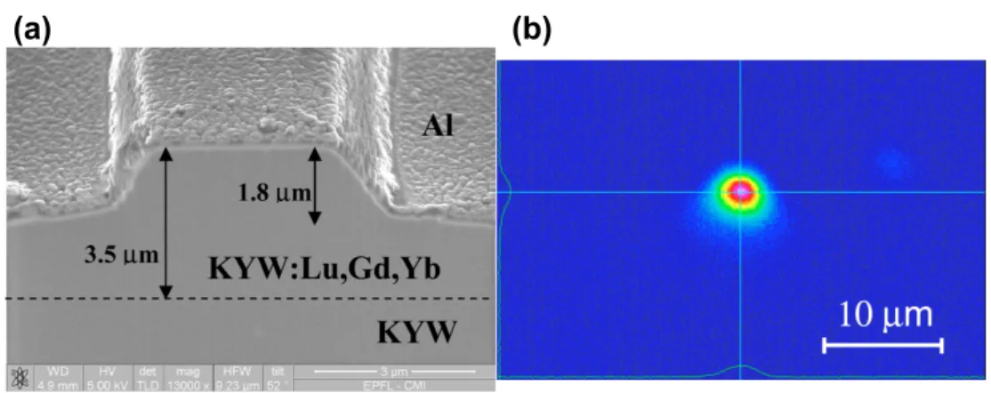
Figure 2.2: Images of a waveguide fabricated by liquid-phase
epi-taxy, (a) Scanning electron microscope image of a 5-µm wide,
1.8-µm high rib waveguide etched in a 3.5-µm thick layer of
KLu0.253Gd0.13Yb0.017Y0.6W. An aluminum top layer is used to reduce
charging effects. (b) Measured intensity distribution of the Yb3+ fluo-rescence guided in the 5-µm wide rib [42].
to achieve a strong refractive index contrast. These crystals with Yb3+ dop-ing provide the highest emission and absorption cross sections for Yb-doped crystalline materials, with values as high as 3· 10-20 cm2 at 1030 nm and 1.33· 10-19 cm2 at 980.6 nm [43, 44]. Typical waveguides can achieve propa-gation losses as low as 0.34 dB/cm [44], and lasing operation at 1µm or at 2 µm for Yb and Tm doping, respectively.
2.2.3
Femtosecond laser inscription
Refractive index change has been realized in dielectric materials by focusing femtosecond laser pulses in order to make passive and active micro-optical de-vices such as directional couplers [45], beam splitters [46], amplifiers [47], and waveguide lasers [48]. Due to the nonlinear absorption proccesses occuring in the material (and the resulting material deformations), the refractive index can
2.2. Dielectric waveguide fabrication methods
be changed and a waveguide can thus be realized. Careful adjustment of the pulse intensity, repetition rate, and writing velocity of the incident fs laser is re-quired to achieve the desired result, since different writing parameters can lead to either an increase or a decrease of the refractive index. There are three types of femtosecond writing techniques, which are summarized in Fig. 2.3. Type-1 waveguiding is achieved when the material is irradiated along a single track with femtosecond pulses of an intensity comparable to the damage threshold of the material. As a result, the refractive index at the center of the damaged track is slighly increased compared to the surrounding areas, allowing waveguiding to occur within the track. Type-2 waveguides are made by two parallel damage tracks written with fs-laser irradiation with intensities higher than the damage threshold. As a result, the material gets damaged in the tracks, which reduces the refractive index at these locations and induces a stress on the surrounding areas. Waveguiding is thus allowed in the surrounding of the tracks. However, the most efficient waveguide is achieved in-between the two tracks where the refractive index contrast is the highest [Fig. 2.3(b)]. Finally, type-3 waveguides are achieved by inscribing many damaged tracks at different depths in the sub-strate. The cross section of the tracks gives the shape of the waveguide end facet [Fig. 2.3(c)], where the refractive index of the undamaged central part is higher than in the damaged surrounding areas, hence forming a waveguide in the inner region. This type of waveguides can have significantly larger dimensions com-pared to the previous ones, which leads to multimode (transverse) operation. This method can be used to realize waveguides in some special materials where types 1 and 2 fabrication methods are not applicable. There are numerous dif-ferent materials that are being used for fs-written waveguides in a wide range of emission wavelengths, spanning from the visible up to 2 µm. The typical di-electric materials are Pr:SrAl12O19 and Pr:YLiF4 for visible emission, Yb:YAG
and Yb:CALGO for 1-µm emission, and ZrF4-BaF2-LaF3-AlF3-NaF (ZBLAN)
possible with emission cross sections of up to 2.2· 10-20 cm2 at 1030 nm and absorption cross section of 0.75· 10-20 cm2 at 940 nm for Yb:YAG [50].
(c)
(b)
(a)
fs laser
Type 1
Type 2
Type 3
Figure 2.3: Femtosecond laser inscription of a waveguide.
2.3
Yb:YAG waveguide lasers
As previously mentioned, dielectric waveguide lasers are a promising solution for efficient high power compact lasers. In CW operation, power levels of up to 5.1 W and slope efficiencies up to 73% have been reported for fs-laser-inscribed channel waveguide lasers [35]. Several Q-switched and CW modelocked dielectric channel waveguide lasers have been demonstrated, and pulse durations down to 285 fs have been realized [51, 52]. Q-switched operation was demonstrated with average output power levels of up to 680 mW [53]. In this section, the combination of femtosecond laser-written crystalline channel waveguides with semiconductor saturable absorber mirrors (SESAMs) is demonstrated for the realization of a high-power Q-switched channel WG laser. The first Q-switched channel WG laser with multiwatt average output power is presented, achieving
2.3. Yb:YAG waveguide lasers pulse energies of up to 1 µJ.
2.3.1
Fabrication
Our waveguides were fabricated at the Institute of Laser Physics in Hamburg by fs-inscription into a Y3Al5O12(Yb:YAG) crystal doped with 7% Yb3+. They
consist of two parallel tracks, which were inscribed by a linear translation of the sample perpendicular to the incident fs-laser beam. These tracks are separated by a distance between 22 and 30µm. Owing to a stress-induced refractive index change, the core of the waveguide is located between the two tracks. Such waveguides are referred to as type-2 waveguides (see section 2.2.3). Here, we superimposed a sine oscillation with an amplitude of 2 to 4µm and a frequency of 70 Hz to the linear translation of the sample performed at a velocity of 25µm/s as schematized in Fig 2.4. A larger refractive index change and a better confinement of the laser mode can be achieved with this modified writing scheme [35]. We adapted a previous WG writing scheme [35, 36, 48] by inserting a pinhole with a diameter of 600µm into the beam of the fs-laser to improve its quality by mode cleaning. As a result of the large distance between the pinhole and the aspheric focusing lens (f = 3.1 mm, NA = 0.68) used for the laser inscription, only the 0th order of the resulting diffraction pattern was transmitted through the lens aperture. The position of the pinhole was adjusted such that the aperture of the lens was filled by the incident beam. For the experiments, we used WGs with a length of 10.4 mm. We experimentally confirmed with a transmission measurement performed at 633 nm that the modified writing parameters of the waveguide reduced optical transmission losses from 1.2 to 0.5 dB/cm.
x y z
(a)
(b)
W(c)
aveguidi ng fs-laser WG chipFigure 2.4: Schematic of the fs-laser writing mechanism. (a) fs-laser sinusoidal translation (along the x axis) superimposed to the linear translation (along the z axis), (b) pair of inscribed tracks (material modification in those areas), (c) resulting waveguiding in-between the tracks.
2.3.2
Experimental setup
The setup for the laser experiments is depicted in Fig. 2.5. The experiments shown here were performed using a WG with a track separation of 26 µm and
a superimposed oscillation with an amplitude of 2 µm. The Yb:YAG WG was
pumped by an optically-pumped semiconductor laser (OPS), also referred to as a vertical external-cavity surface-emitting laser (VECSEL) or semiconduc-tor disk laser [21], delivering up to 9 W of power at 969 nm with an M2 < 2.
The slightly elliptical collimated pump beam was focused onto the waveguide facet using a lens of 30-mm focal length. This resulted in a pump spot diam-eter of 23 µm x 19 µm. The waveguide mode field diameter is approximately 18µm x 22 µm at 969 nm. We estimated the coupling efficiency ηc by
calculat-2.3. Yb:YAG waveguide lasers
λ/2-waveplate
M1
λ/2-waveplate
optical
isolator
lens
OPS
Yb:YAG
waveguide
detection
air gap
cavity
M2
HR or
SESAM
Figure 2.5: Experimental setup of the CW and Q-switched waveguide lasers. OPS laser at 969 nm as pump source; mirror M1, highly trans-parent (HT) at 969 nm, HR at 1030 nm; mirror M2, transtrans-parent at 1030 nm, HR at 969 nm.
ing the overlap integral [54] of the waveguide and pump modes to be ηc= 97%.
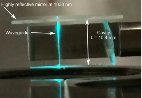
The laser cavity length is determined mainly by the length of the waveguide chip. The WG chip was pumped through the uncoated front facet, which also served as an output coupler for the WG cavity. The second cavity end mirror was either a highly reflective (HR) mirror for CW operation or a SESAM [23] for Q-switched operation. Each of them was placed close to the WG end facet, as illustrated in Fig. 2.6 for the waveguide laser in CW operation. Owing to the Fresnel reflection of 8.4% at 1030 nm at the front facet, the cavity exhibits a resulting total output coupling of 91.6%. The laser output light was separated from the pump light by a dichroic mirror M1, which was placed in front of the waveguide. An additional dichroic mirror (M2) was placed in front of the char-acterization setup to filter out residual pump light reflected on the front facet of the crystal. The SESAM was mounted on a Peltier-cooled holder for tempera-ture control. During the entire experiment, the temperatempera-ture of the SESAM was set to 17oC. However, no significant change of the pulsed laser operation has been observed when varying the SESAM temperature between 15oC and 35oC.
Waveguide
Highly reflective mirror at 1030 nm
Cavity L = 10.4 mm
Figure 2.6: Picture of the waveguide laser in CW operation. The
waveguide is made visible by parasitic fluorescence green light resulting from the optical pumping.
The SESAM has a saturation fluence of 57µJ/cm2, a modulation depth of 0.7%, and nonsaturable losses of 0.2%, when characterized with picosecond pulses at a wavelength of 1030 nm [55]. The recombination time of this SESAM was not measured, but is expected to be <100 ps, which is orders of magnitude shorter than the achieved pulse duration. Therefore, carrier recombination occurs dur-ing the presence of the pulse, whereas the states are immediately refilled leaddur-ing to the bleaching of the absorber. No index matching fluid was applied between the SESAM and the waveguide end facet. Hence, a tiny airgap was left, which could be adjusted by a piezoelectric ring actuator placed on a mirror mount. During the entire experiment the air gap was kept between 10 and 100µm. The pump power was measured after the mirror M1 in front of the focusing lens. In the following, we consider as pump power the measured pump power corrected by the transmission of the focusing lens (97.5%) and the Fresnel reflection of
2.3. Yb:YAG waveguide lasers
the waveguide end facet (8.4%), and assuming the incoupling efficiency to be unity. It should be noted that this assumption leads to a minor underestimation of the actual efficiencies. The laser average output power was measured after the mirrors M1 and M2 and was corrected by their reflection and transmission coefficients, respectively. For the characterization of the Q-switched operation, a fraction of the laser power was sent to a high-speed InGaAs photodetector with 45-GHz bandwidth (Newport 1014), connected to an oscilloscope or an RF spectrum analyzer. Another fraction of the laser power was sent to an optical spectrum analyzer (Yokogawa AQ6370C) for wavelength characterization.
2.3.3
Laser results
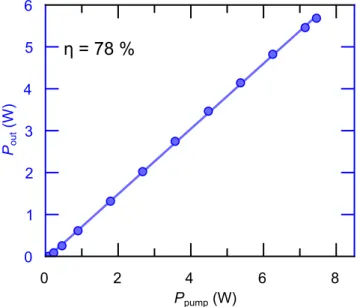
For CW operation, the HR mirror was mounted on the piezo-controlled mount, as described above. In this configuration, laser operation started at 89 mW of pump power. A maximum output power of 5.7 W was achieved at a pump power of 7.5 W, corresponding to a slope efficiency of 78% (Fig. 2.7). These results outperformed earlier high power Yb:YAG waveguide lasers [35] and show that the writing parameters of the waveguide were considerably improved. For Q-switched operation the HR mirror was replaced by the SESAM. In this case, Q-switching started at the laser threshold corresponding to a pump power of 102 mW. During the entire experiment, no Q-switched modelocking was ob-served. A maximum average output power of 5.6 W was achieved at a pump power of 7.7 W. The low modulation depth and nonsaturable losses of the SESAM allowed for a high-power multiwatt Q-switched pulsed operation with an only slightly reduced slope efficiency of 74% [Fig. 2.8(a)]. The optical spec-trum of both operation modes looks very similar, and is centered at 1030 nm with a full-width-half-maximum (FWHM) of ∼0.5 nm. With increasing pump power the stability of the Q-switching decreased. However, it was possible to compensate for this effect by fine tuning the air gap between the SESAM and
0 2 4 6 8 Ppump (W) 0 1 2 3 4 5 6 Pout (W)
η = 78 %
Figure 2.7: Output power (Pout) versus pump power (Ppump) for the
CW laser configuration showing a slope efficiency η of 78%.
the waveguide chip. The resulting etalon effect significantly changed the cou-pling into the SESAM and thus its parameters [56]. By doing so, however, the slope efficiency was reduced by approximately 5% as depicted in Fig. 2.8(b). At the same time, the maximum average output power decreased to 5.3 W. In both cases, the maximum average output power was only limited by the available pump power. The pulse energy versus pump power is depicted in Figs. 2.8(a) and 2.8(b) (red curves). With increasing pump power the pulse energy increased and approached 1 µJ at the maximum average output power of 5.6 W. For the stable Q-switching configuration [Fig. 2.8(b)] the pulse energy varies approxi-mately linearly with the pump power, while the dependence is distorted for the power-optimized (unstable) Q-switching configuration [Fig. 2.8(a)]. The dip ob-served in the pulse energy in Fig. 2.8(a) at a pump power of 5.4 W goes along with an abrupt increase of the repetition rate from 4.1 to 5.5 MHz. Figure 2.9 shows the oscilloscope trace of a fully modulated single pulse and the pulse train