READ THESE TERMS AND CONDITIONS CAREFULLY BEFORE USING THIS WEBSITE.
https://nrc-publications.canada.ca/eng/copyright
Vous avez des questions? Nous pouvons vous aider. Pour communiquer directement avec un auteur, consultez la
première page de la revue dans laquelle son article a été publié afin de trouver ses coordonnées. Si vous n’arrivez pas à les repérer, communiquez avec nous à PublicationsArchive-ArchivesPublications@nrc-cnrc.gc.ca.
Questions? Contact the NRC Publications Archive team at
PublicationsArchive-ArchivesPublications@nrc-cnrc.gc.ca. If you wish to email the authors directly, please see the first page of the publication for their contact information.
NRC Publications Archive
Archives des publications du CNRC
This publication could be one of several versions: author’s original, accepted manuscript or the publisher’s version. / La version de cette publication peut être l’une des suivantes : la version prépublication de l’auteur, la version acceptée du manuscrit ou la version de l’éditeur.
Access and use of this website and the material on it are subject to the Terms and Conditions set forth at
Effectiveness of toppings to control flanking transmission in
lightweight framed floors
Nightingale, T. R. T.; Halliwell, R. E.; Quirt, J. D.
https://publications-cnrc.canada.ca/fra/droits
L’accès à ce site Web et l’utilisation de son contenu sont assujettis aux conditions présentées dans le site LISEZ CES CONDITIONS ATTENTIVEMENT AVANT D’UTILISER CE SITE WEB.
NRC Publications Record / Notice d'Archives des publications de CNRC:
https://nrc-publications.canada.ca/eng/view/object/?id=ef136dae-5033-4658-a1ec-f66c4fcf9305 https://publications-cnrc.canada.ca/fra/voir/objet/?id=ef136dae-5033-4658-a1ec-f66c4fcf9305
Effectiveness of toppings to control flanking
transmission in lightweight framed floors
Nightingale, T.R.T.; Halliwell, R.E.; Quirt, J.D.
NRCC-45673
A version of this document is published in / Une version de ce document se trouve dans
Joint Meeting of CIB WG51 Acoustics and European Acoustical Association, Sevilla, Spain
,
Sept. 15-21, 2002, pp. 1-6Effectiveness of toppings to control flanking transmission in lightweight
framed floors
PACS REFERENCE: 43.55.p, 43.40.p
T.R.T. Nightingale, RE Halliwell, JD Quirt
National Research Council Canada, Institute for Research in Construction, Building M-27, Montreal Road, Ottawa, Ontario, K1A 0R6 CANADA
e-mail: trevor.nightingale@nrc.ca
ABSTRACT
This paper examines the effectiveness of toppings to control direct and flanking paths for an impact source placed on a wood-I joist floor. The change in flanking sound insulation due to adding a topping is shown to be different for paths where energy propagates perpendicular to the joists, compared to those where energy propagates parallel to the joists. Floor vibration mappings reveal that a topping will change not only the power injected but also the propagation losses across the floor. The most effective toppings reduce input power and increase propagation losses relative to the bare floor. One type of topping exhibits significant improvement in the flanking sound insulation in one direction and a significant worsening in the other. The results are used to establish the basis for a semi-empirical model for flanking transmission in structures with very high internal losses.
INTRODUCTION AND EVALUATION METHODS
This paper compares the impact sound pressure levels (ISPL) measured between room pairs AB and AC for the assemblies shown in Figure 1 and Figure 2. From these comparisons it is demonstrated that, in general, the improvement for direct transmission will not match that for flanking transmission involving the floor surface. The change in the impact sound insulation between room pair AB is examined with the joists parallel to the junction (Figure 2), and with them perpendicular (Figure 1). The improvement for floor flanking paths can be strongly dependent on joist orientation.
The wall construction details of the assemblies in Figure 1 and Figure 2 are identical, each having single-stud framing with glass fiber insulation. There were two layers of 16 mm gypsum board attached directly to the studs in rooms A and C, and 1 layer of 16-mm gypsum board attached via resilient channels to the other side. Both floors comprised 18-mm OSB subfloor, 300-mm wood-I joists, glass fiber insulation, resilient channels, and two layers of 16-mm gypsum board. The OSB subfloor was continuous under the partition wall in both cases. In the case with the joists perpendicular to the partition wall, the joists were continuous under the wall. Both floors had continuous framing members to provide increased resistance against wind and seismic loading. When the joists were parallel, blocking (for fire resistance) was provided by
continuing the gypsum board on the room C side to the under side of the subfloor, and by adding a layer of gypsum board to the room B side of the joist at the junction. With the joists perpendicular to the wall, blocking was achieved by the insertion of sections of a wood-I joist at the junction.
A B
C D
A B
C D
Figure 1: Sketch of the test specimen with joists perpendicular to the junction.
Figure 2: Sketch of the test specimen with joists parallel to the junction.
The two toppings shown in Table 1 are a small subset of those studied in a recent IRC/NRC study [1], but are sufficient to identify the important trends. The toppings were applied in both rooms A and B.
Material Nominal Thickness,
mm
Surface Density, kg/m3
Application
OSB overlay 18 mm 11.7 Stapled 305 mm o.c.
Gypsum-concrete 25 mm 47.1 Bonded with agent
Table 1: Properties of the topping layers and their method of application to the subfloor.
The oriented strand board (OSB) overlay consisted of adding a second layer of the subfloor material. The OSB overlay was not continuous under the partition wall, stopped short of the sole plate of the wall, and did not contact the gypsum board. The bonded gypsum-concrete was applied according to the manufacturer’s recommended practice which is to apply a bonding agent to the subfloor and then pour the slurry in place allowing bonding to all surfaces contacted. This bonding includes the gypsum board of walls in rooms A and B. Generally following the procedures of ISO 140-7, the impact sound pressure levels were measured with the ISO hammer box located at the same four positions near the center of the floor in room A, approximately 2.3 m from the wall/floor junction.
There are two primary transmission paths from room A to room C for a floor impact source. The flanking path from the floor surface to the lower wall (in room C) being less important than the direct for the cases considered here. Since both of these paths involve the floor this allows direct comparison of the ISPL with and without the topping to assess the effectiveness of the topping to control direct transmission. For room pair AB, the only transmission path is flanking involving the floor in room A. Thus the ISPL measured in room B with and without a topping can be used to assess the effectiveness of toppings to control floor flanking paths.
EFFECT OF TOPPING ON DIRECT AND FLANKING TRANSMISSION
Figure 3 shows the change in the receiver room ISPL due to adding an 18 mm OSB overlay. The figure indicates that the overlay reduced the ISPL (improved sound insulation) for both direct transmission (between room pair AC) and flanking transmission (between room pair AB).
For frequencies above 200 Hz, regardless of the orientation of the joists, there is a greater reduction in ISPL for room pair AB than AC. The OSB topping is more effective at controlling flanking transmission involving the floor surface than direct transmission.
Figure 3: Change in impact sound pressure level due to applying the 18 mm OSB overlay as a function of the orientation of the joists shown in Figure 1 and Figure 2.
A
B
C
D
Fastened 18mm OSB topping
-16 -14 -12 -10 -8 -6 -4 -2 0 2 4 6 8 63 125 250 500 1k 2k 4k Frequency, Hz AC
Joists perpendicular to junction
AB
Joists perpendicular to junction AB
Joists parallel to junction
AC
Joists parallel to junction
Figure 4 shows that for both direct and flanking transmission, adding a gypsum-concrete topping bonded to the subfloor will increase the ISPL relative to the bare floor in the high frequencies. The most important feature however is the relation of curves. Unlike Figure 3 the change to the direct transmission (room pair AC) is bounded above and below by the changes to the flanking transmission (room pair AB). For one joist orientation, the topping is more effective at controlling flanking transmission (room pair AB) than direct transmission (room pair AC) while for the other joist orientation the same topping is more effective at controlling direct transmission than flanking.
Figure 4: Change in impact sound pressure level due to applying the bonded 25 mm gypsum-concrete topping as a function of the orientation of the joists shown in Figure 1 and Figure 2.
A
B
C
D
Bonded 25mm gypsum-concrete topping
-25 -20 -15 -10 -5 0 5 10 15 20 63 125 250 500 1k 2k 4k Frequency, Hz AC
Joists perpendicular to junction AB
Joists perpendicular to junction AB
Joists parallel to junction
AC
Joists parallel to junction
In the frequency range 160 – 2000 Hz with the joists perpendicular to the junction, the topping attenuates floor flanking paths more than direct transmission though the floor. The opposite is true when the joists are parallel to the junction since in the frequency range 400 – 2000 Hz the topping is better at controlling direct transmission than flanking transmission.
RELATING THE ISPL CHANGE CAUSED BY THE TOPPING TO CHANGES IN STRUCTURE BORNE ATTENUATION
If the floor assemblies considered here can be shown to be highly damped, such that vibration energy is dominated by the direct field from a localized source (i.e., ISO hammer box), then flanking transmission between the source room and the receiver room can be approximately described by five mechanisms. They are power injection, power attenuation while travelling to the flanking junction, junction attenuation, power attenuation between the junction and the point of radiation in the receiver room, and conversion from structure borne to airborne power. Adding a topping should change the injected power in the same way for both direct and flanking transmission. Thus, if the topping is more effective at controlling flanking transmission than direct transmission, it is likely that adding the topping changed one, or more, of the four remaining attenuation mechanisms. This section shows that the bare OSB floor is highly damped and that adding a topping significantly alters attenuation in the source surface. These changes in structure borne attenuation qualitatively explain the trends in the ISPL due to adding a topping.
Also, if adding a topping changes the rate of structure borne attenuation differently for the two joist orientations then the change in AB ISPL due to applying a topping will be different when applied to the construction of Figure 1 as compared to Figure 2.
Velocity mappings can be convenient tools to qualitatively determine the presence of structure borne attenuation in the measured surface. Figure 5 shows the mapping for the bare OSB subfloor in rooms A and B when the joists are oriented perpendicular to the flanking junction (Figure 1). Examining the contour lines in the source room indicates that the floor is highly damped (shown by the closely spaced contours around the clearly identifiable source). Direct field from the source likely dominates the vibration response at all locations on the source surface. The same figure also shows that the floor is not homogeneous and isotropic, (shown by the irregularly shaped contours around the source). The closeness of the contour lines in the source room indicates that there is much greater attenuation perpendicular to the joists than parallel. The location of the junction is also clearly identifiable by the closely spaced contours running parallel to the junction. The receiver surface exhibits comparatively uniform vibration response compared to the source surface.
Figure 5: Mapping of the measured surface velocity (dB arb.) at 2 kHz in rooms A and B for the bare floor of the Figure 1 assembly (joists oriented perpendicular to the junction). The location of the ISO hammer box is indicated in room A. The heavy solid line indicates the wall/floor junction. 79 77 75 73 71 81 83 85 69 87 89 91 67 93 95 65 69 97 99 0 1 2 3 4 5 6 7 8 9 4.4 4.0 3.6 3.2 2.8 2.4 2.0 1.6 1.2 0.8 0.4 0.0 Bare Subfloor 2000 Hz
Distance from rear facility wall, m
Dista n ce f ro m side f a ci lity w a ll, m 55 59 63 67 71 75 79 83 87 91 95 99 103 105
Rough estimates of propagation loss can be obtained from the mappings by simply plotting velocity levels measured along two orthogonal draw-away lines from the source. One line is parallel to the joist orientation, while the other is perpendicular to the joist orientation. For all cases draw-away data are available for the source room floor surface in room A. Extended draw-away curves that include the receiver room B are only available for cases where the joists were perpendicular to the junction.
Figure 6 indicates that without a topping, structure borne power travelling toward the junction experiences considerably greater attenuation when the joists are parallel to the junction, that is
the power must flow perpendicular to the joists. The same figure also shows that when the OSB overlay is added the structure borne attenuation is significantly increased for both joist orientations (perpendicular to the junction, as well as parallel).
Figure 6: Surface vibration levels at 1 kHz measured along two orthogonal lines from the source with and without the fastened 18-mm OSB overlay. 85 95 105 115 125 135 145 0 1 2 3 4 5 6 7 8
Distance from ISO Hammer Box, m
Surfac e Veloc ity , dB (arb) Room A No Topping
Joists parallel to junction
No Topping
Joists perpendicular to junction
18mm OSB Overlay Joists parallel to junction
18mm OSB Overlay Joists perpendicular to junction
Room B junction
Comparing the vibration levels on either side of the junction with and without the OSB overlay suggests that the OSB overlay may slightly affect junction attenuation. If it is assumed that the receiver room radiation will be also largely unaffected then the trends observed in Figure 6 suggest that the improvement for flanking transmission will be similar for both joist orientations. Also, since the topping causes a greater change in floor vibration level at the flanking junction than the area close to the impact source, the improvement for impact sound insulation should be greater between room pair AB than for AC (i.e., greater improvement for flanking transmission than for direct transmission). Qualitatively, these are consistent with the change in measured impact sound pressure levels shown in Figure 3.
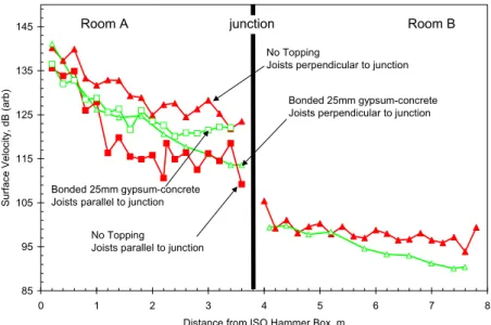
Figure 7: Surface vibration levels at 1 kHz measured along two orthogonal lines from the source with and without the bonded 25-mm gypsum-concrete. 85 95 105 115 125 135 145 0 1 2 3 4 5 6 7 8
Distance from ISO Hammer Box, m
S u rf ace V e lo ci ty , dB (arb) Room A No Topping
Joists parallel to junction
No Topping
Joists perpendicular to junction
Bonded 25mm gypsum-concrete Joists parallel to junction
Bonded 25mm gypsum-concrete Joists perpendicular to junction
Room B junction
Figure 7 shows that adding the bonded gypsum-concrete topping applied to the same bare floor increases propagation losses when the joists are perpendicular to the junction. Here the vibration energy propagates parallel to the joists to reach the junction. The opposite is true when the joists are parallel to the junction, since to reach the junction the vibration energy must propagate perpendicular to the joists. Thus, the bonded topping will be less effective when
applied to flanking paths where the joists are parallel to the junction. This is consistent with the trends in the impact sound pressure levels shown in Figure 4.
DISCUSSION
The vibration data in Figure 6 highlight the mechanisms involved in flanking transmission between the floor surface in room A and the floor surface in room B. Vibration energy is attenuated with distance, and the rate of attenuation depends on the direction relative to the joists. With the joists parallel to the direction of propagation, the levels decrease reasonably monotonically with distance up to the joint, indicating that the field is not diffuse. This was confirmed by a detailed mapping of the complete floor (Figure 5). As a first order approximation only the direct field need be considered. Thus, the product of the injected power and an attenuation factor will give the effective power at the junction. The draw-away curves clearly demonstrated that a topping modifies attenuation in the floor surface. Junction attenuation should be estimated using the difference in vibration levels close to the junction rather than space average levels because of the strong vibration gradient in the source surface. Using this criterion, Figure 6 shows that adding the OSB overlay may slightly affect junction attenuation. The receiver room vibration levels exhibit very little attenuation with distance when compared to those of the source plate. The cause of this is not known, but is under investigation. The receiver surface will have two radiation mechanisms, one due to the reverberant field and other due to the near field of forcing points. The relative importance of these mechanisms has not been examined for these floors. Qualitatively, the draw-away curves illustrate the behaviours that would have to be included in a prediction model for such assemblies.
CONCLUSIONS
A topping that increases propagation losses relative to the bare floor will be more effective in controlling flanking transmission than direct transmission. This has important implications; results for direct transmission under laboratory conditions (ISO 140-5) can not be applied to predict changes in flanking paths when the added topping significantly changes propagation attenuation. These data suggest that for wood-I joist floors the error may exceed 10 dB.
The results showed that because structure borne attenuation is a function of joist orientation the effectiveness of toppings to control flanking transmission is a function of the orientation of the joists.
The high structural attenuation in the floor surface will make the impact sound pressure level extremely sensitive to the location of the hammer box when there is significant flanking involving the floor surface. A fair comparison of results can only be made if the source is located a uniform distance from the flanking junction.
ACKNOWLEDGEMENTS AND REFERENCES
This work was supported by a consortium that included Canada Mortgage and Housing, Forintek Canada, Marriott International, Owens Corning, Trus Joist, and USG.
1). R. E. Halliwell, J. D. Quirt, and T. R. T. Nightingale, “Construction details affecting flanking transmission in wood framed multifamily dwellings,” Proceedings INTERNOISE 2002, Dearborn Michigan, USA