HAL Id: hal-02087150
https://hal.laas.fr/hal-02087150
Submitted on 1 Apr 2019
HAL is a multi-disciplinary open access
archive for the deposit and dissemination of
sci-entific research documents, whether they are
pub-lished or not. The documents may come from
teaching and research institutions in France or
abroad, or from public or private research centers.
L’archive ouverte pluridisciplinaire HAL, est
destinée au dépôt et à la diffusion de documents
scientifiques de niveau recherche, publiés ou non,
émanant des établissements d’enseignement et de
recherche français ou étrangers, des laboratoires
publics ou privés.
Development of integrated smart nose based on WO3
gas sensors
H. Chalabi, Philippe Menini, Emmanuel Scheid, Ludovic Salvagnac,
Véronique Conédéra, Khalifa Aguir
To cite this version:
H. Chalabi, Philippe Menini, Emmanuel Scheid, Ludovic Salvagnac, Véronique Conédéra, et al..
De-velopment of integrated smart nose based on WO3 gas sensors. Eurosensors XX, Sep 2006, Göteborg,
Sweden. �hal-02087150�
DEVELOPMENT OF INTEGRATED SMART NOSE BASED ON WO
3GAS
SENSORS
H. Chalabi
1*, Ph. Menini
1, E. Scheid
1, L. Salvagnac
1, V. Conedera
1, K. Aguir
2 1LAAS-CNRS, Université Toulouse III, 7 avenue du Colonel Roche, 31077 Toulouse Cedex 4, France 2
L2MP-CNRS,Université Paul CEZANE, FST, Av. E.N. Niémen, 13397 Marseille cedex 20, France *Habib CHALABI, Tel: (+33) 5 61 33 63 88, Fax: (+33) 5 61 33 62 08, e-mail: [email protected]
Abstract: This article deals with the conception and realisation of a new architecture of integrated electronic
nose based on silicon microhotplates and WO3 thin films. The first part of this work describes technological choices to elaborate a single gas sensor with low consumption (˜100 mW to reach 600°C), low thermal inertia (˜30ms), above all with a good heater stability. By consideration of response times and relative resistance variations from sensor response curves, it is possible firstly to discriminate different gas mixtures and secondly to evaluate gas concentrations by using mathematical analysis.
Keywords: Microtechnology; Semi-conducting Gas Sensors; Electronic nose; WO3 Thin film.
INTRODUCTION
Presently, gas sensors presents every year more and more interests in a lot of fields of application like automotive, home automation, environment, agro-industry…. Optical sensors are generally well adapted with good accuracy but to much bulky and expansive. At the opposite, semiconducting gas sensors are more and more attractive even their characteristics remain just enough : most of commercial simple metal oxide gas sensors carry out poor selectivity and/or low response time and/or a low reproducibility and/or instabilities from polysilicon heater resistance that yield to minimize their lifetime.
In this article, some technological solutions are firstly developed to minimize the heater time drift in allowing higher temperature range and good homogeneity on the active area. Secondly, it is presented an integrated multi-sensor platform which includes independent platinum heater resistances and interdigitated platinum electrodes. This heater has been optimised geometrically by numerical modelling. This platform associated with an appropriate data treatment (factorial discriminate analysis or neural network) allows to realize an “electronic nose”.
SINGLE GAS SENSOR DESCRIPTION
Gas sensor presently used can be decomposed in two parts: a metal oxide sensitive layer and a silicon microhotplate. A first generation of microhotplate has been initially developed by LAAS-CNRS in collaboration with MOTOROLA [1], and currently exploited by MicroChemical Systems S.A [2]. This structure which includes polysilicon heater and thin insulated membranes, allows low power consumption (can reach 500°C with less than 100mW) and very low thermal inertia (minor than 25 ms from ambient to 500°C).
Nowadays, LAAS-CNRS and L2MP develop conjointly this kind of structure with a polycrystalline silicon heater and WO3 thin sensitive layer.
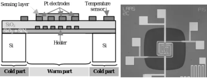
Figure 1: Schematic and top of view of gas sensors with platinum heater.
Even if this technology has already presented good results and is relatively well controlled, it is not free of defaults.
Some studies show that polysilicon heater drifts significantly [3]. Indeed there is a not reversible resistance drift. That needs more power to reach the same temperature. However the more important power is, the more heater resistor degrades…
Moreover the heater aging acts on the gas sensitivity: thermal conditioning of sensitive layer is directly bounded to detection phenomenon. However optimum sensitivity for one gas presents generally a restricted spectrum of operating temperature. In addition, if the sensor is used with pulsed operating mode, temperature variations can have a negative effect on kinetic response of sensitive layer (or if the temperature is not well controlled).
To free itself of this major drawback, it is very important to obtain a good stability of the heater resistor. For that, two choices are considered:
§ To develop a power control unit eventually in pulsed mode but it reduces significantly the sensor life time without solving the heater drift problem.
§ To design a new more stable microhotplate.
Sensing layer Pt electrodes
Heater
Si Si
SiO2
Cold part Warm part Cold part
SiO2 + SiNx
Temperature sensor
A new generation of microhotplate was conceived without any polysilicon resistor. This structure is detailed on Fig. 1. It consists of a platinum resistor. The use of this material would have theoretical advantage to reach high level of temperature (around 600°C compare to 450°C with polycrystalline silicon). Finally, Pt-heater can be use such as a metallic thermistor in aimed to control more accurately sensitive layer temperature.
TECHNOLOGICAL PROCESS
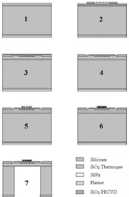
The micromachined hotplate is realized on double-side polish silicon substrate (Fig. 2).
Figure 2: Description of technological process.
(1) Membrane with low residual stress is
constituted by LPCVD deposit of SiO2/SiNX (1.4/0.6µm) bi-layer. (2) Heater is obtained by lift-off process. It consists of Pt/Ti (0.01/0.15µm) deposit by evaporation with electron beam. In fact if platinum is know like a stable material, titanium is know too to have a poor stability at high temperature [3]. Resistivity vs temperature 2.0E-05 3.0E-05 4.0E-05 5.0E-05 6.0E-05 7.0E-05 8.0E-05 350 400 450 500 550 600 Temperature (°C) Resistivity (Ohms.cm) Ti=400A Ti=300A Ti=200A Ti=100A
Figure 3: Resistivity of Pt/Ti deposit vs temperature.
So this Pt/Ti deposit has been optimised according to titanium thickness and annealing temperature (Fig. 3) in aim to reduce stress and in other hand increase stability of thermal behaviour for our operating range.
(3) The heater is then insulated by a PECVD
deposit of SiO2, follow by (4) contact opening. (5) Then, interdigitated electrodes are realized by similar metallization of the heater.
(6) The sensitive layer of WO3 (0.03µm) is deposit
by RF magnetron sputtering [5]. Finally membrane is releasing on the backside by DRIE (Deep Reactive Ion Etching). DRIE have high speed of etching (˜3µm.min-1) and give vertical side that allows a reduction of height.
MICROHEATER CHARACTERIZATION
In comparison at polysilicon heater, a new design of heater has being to develop due to low resistivity of platinum. So we have make electro-thermal studies with FEM tool ANSYS, confirmed by IR measurements.
Figure 4: Thermal distribution of gas sensors with platinum heater simulated with ANSYS software and by
IR measurement.
We have been adopted a double spiral heater with variable pitch. The temperature of this shape is better than the classical meandered heater (with or without constant pitch) witch presents a very high radial temperature gradient and often hot spot (can be destructor for the sensitive layer). Thermal distribution simulated and with IR measurement are presented in Fig. 4. With 0.03°C.µm-1 from centre to border, the microhotplate allows a good behaviour of sensitive layer.
Power vs temperature (spiral heater)
75 175 275 375 475 30 40 50 60 70 80 Power (mW) Temperature °C) Simulation IR
Figure 5: Temperature reach versus power for a double spiral heater.
We can observe temperature reach versus power (Fig. 5), and conclude that the microhotplate study is a low consumption device (˜500°C with less 100mW of power). Simulation results are in agreement with the IR measurement. Else t he heater seems stable after several hours operating mode repeating several days with constant power supply.
ELECTRONIC NOSE
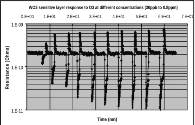
The gas sensors presented with WO3 layer is particularly well adapted to detect ozone. Some tests are realized in closed enclosure and show good results. After have been determinate the best operating temperature, we have been varied the O3 concentration like example in Fig. 6. The response without gas shows the good stability of sensitive layer. Then the detection threshold around 30ppb of O3 shows a good sensibility.
WO3 sensitive layer response to O3 at different concentrations (30ppb to 0.8ppm)
1.E-11 1.E-10 1.E-09
0.E+00 1.E+01 2.E+01 3.E+01 4.E+01 5.E+01 6.E+01 7.E+01
Time (mn)
Resistance (Ohms)
Figure 6: WO3 sensitive layer response to O3 at different
concentrations (30ppb to 0.8ppm).
However in gas mixture detection is more difficult. With current analysis method, one sensor doesn’t allow discriminate efficiently gas. So gas sensors composed with only one die are not appropriate for detection in complex mixture.
To improve this main problem, first solution consists to improve analysis method [6] but this solution can meet some limitations (gas interfering number…). Other solution consists to increase number of gas sensors.
So we work to process on full integrated array sensors composed to 4 (Fig. 7) and 6 dies. Challenges of this technology are the reduction of height on the one hand, and integration of different layers on the second hand in aim to increase detection performance and particularly the selectivity.
We have reduced significantly the height of the structure: simple sensor like figure 1 has 2x2mm area whereas the multisensors with 4 cells have only 2.2x2.2mm area. With keeping the same heated area/membrane ratio around 2 [7], simulation give good results, similar that the simple
sensor with a spiral heater. Else we have reduced the number of pad with jointly ground of the different heater.
Figure 7: Top of view of the multi-sensors chip with platinum heater and interdigitated electrodes.
Integration of different layers is the most critical point: it exist several deposit methods of semiconducting metal oxide (sputtering, screen-printing, coating…), and particularly different thermals treatments. That implies a specific studie witch is in progress. So at moment we use only one sensitive layer of WO3. But in goal to obtain different information about gas from one cell to another, we have integrated different interdigitated electrodes like Fig. 8. These multisensors are then mounted in T0 -8 socket for testing.
Figure 8: Multi-sensors and different interdigitated electrodes.
CONCLUSION
A multi-sensor platform including independent platinum heater resistances and interdigitated platinum electrodes has been realized. A dedicated bench test has being developed for this new structure. Tests under gas mixture, associated to research of an appropriate data treatment, are in progress.
2.2mm
REFERENCES
1. S. Astié, Intégration d’un capteur de gaz à oxyde semi -conducteur sur silic ium, PhD thesis (n°3309), Université Paul Sabatier de Toulouse, 1998.
2. H. Delprat and al., New Generation of Micro Machined Silicon Gas Sensors: Nano-structured Pd- and Pt-doped Tin Dioxide Sensitive Layers for the Detection of Hazardous Gases, EurosensorsVIII, 12-15 Sept 2004, Rome, Italy.
3. J. Puigcorbé and al., High temperature degradation of Pt/Ti electrodes in micro-hotplate gas sensors, J. of Micromechanics and Microengineering, 13 (2003), pp 119-124.
4. C. ROSSI and al., Theoretical and experimental study of silicon micromachined microheater with dielectric stacked membranes, Sensors and Actuators A63 (1997), pp183-189.
5. K. Aguir and al., Electrical properties of reactively sputtered WO3 thin films as ozone gas sensor, Sensors
and Actuators B 84 (2002), pp1-5.
6. F. Parret, Méthode d’analyse selective et quantitative d’un mélange gazeux à partir d’un microcapteur à oxyde métallique nanoparticulaire, PhD thesis, INP Toulouse, 2006.
7. I. Simon and al., Micromachined metal oxide gas sensors: opportunities to improve sensor performance, Sensors and Actuators B 73 (2000), pp1-26.