Publisher’s version / Version de l'éditeur:
Tunnelling and Underground Space Technology, 19, Feb. 1, pp. 97-110, 2004-02-01
READ THESE TERMS AND CONDITIONS CAREFULLY BEFORE USING THIS WEBSITE. https://nrc-publications.canada.ca/eng/copyright
Vous avez des questions? Nous pouvons vous aider. Pour communiquer directement avec un auteur, consultez la
première page de la revue dans laquelle son article a été publié afin de trouver ses coordonnées. Si vous n’arrivez pas à les repérer, communiquez avec nous à PublicationsArchive-ArchivesPublications@nrc-cnrc.gc.ca.
Questions? Contact the NRC Publications Archive team at
PublicationsArchive-ArchivesPublications@nrc-cnrc.gc.ca. If you wish to email the authors directly, please see the first page of the publication for their contact information.
NRC Publications Archive
Archives des publications du CNRC
This publication could be one of several versions: author’s original, accepted manuscript or the publisher’s version. / La version de cette publication peut être l’une des suivantes : la version prépublication de l’auteur, la version acceptée du manuscrit ou la version de l’éditeur.
For the publisher’s version, please access the DOI link below./ Pour consulter la version de l’éditeur, utilisez le lien DOI ci-dessous.
https://doi.org/10.1016/j.tust.2003.08.005
Access and use of this website and the material on it are subject to the Terms and Conditions set forth at
Effect of eccentricity and bonding on behaviour and performance of sliplined pipe
Zhao, J. Q.; Daigle, L.; Rajani, B. B.
https://publications-cnrc.canada.ca/fra/droits
L’accès à ce site Web et l’utilisation de son contenu sont assujettis aux conditions présentées dans le site LISEZ CES CONDITIONS ATTENTIVEMENT AVANT D’UTILISER CE SITE WEB.
NRC Publications Record / Notice d'Archives des publications de CNRC:
https://nrc-publications.canada.ca/eng/view/object/?id=feb1cc3b-b670-47de-97d1-d50fdccd2c7e https://publications-cnrc.canada.ca/fra/voir/objet/?id=feb1cc3b-b670-47de-97d1-d50fdccd2c7e
Effect of eccentricity and bonding on behaviour of sliplined pipe
Zhao, J.Q.; Daigle, L.; Rajani, B.B.
NRCC-45993
A version of this document is published in / Une version de ce document se trouve dans : Tunnelling and Underground Space Technology, v. 19, no. 1, Feb. 2004, pp. 97-110
Effect of Eccentricity and Bonding on
Behaviour of Sliplined Pipe
Jack Q. Zhao1, Lyne Daigle2 and Balvant B. Rajani3
1
Transportation, Utilities and Public Works Structural and Transit Services Division 560 Rochester St., 3rd Floor, Ottawa, ON
Canada K1S 5K2
2,3
Institute for Research in Construction National Research Council Canada
M-20, Montreal Road, Ottawa, ON Canada K1A 0R6
1 – Senior Structural Project Manager, Corresponding author, Phone: (613) 580-2424 ext. 20130, Fax: (613) 560-6079
email: JackQ.Zhao@Ottawa.ca
2 – Technical Officer
Abstract: Sliplining is one of the trenchless technologies that can be used in the rehabilitation of
an underground pipe. Typically the annular space between the host pipe and the liner is grouted. Common practice is to design the liner pipe to withstand full internal and external loads, without considering the structural contributions from the existing host pipe and from the grout. This over-simplified practice is followed partially because the behaviour of grouted sliplined pipes and the roles that the pipes and grout play in such a system are not well understood. This paper presents some insight into the behaviour of grouted sliplined pipes with the results of a
numerical (finite element) analysis on the effects of eccentricity between the liner and host pipe and bonding at the pipe interfaces.
This study shows that the direction of eccentricity between the liner and host pipe in a grouted sliplined pipe has a significant impact on the behaviour of the pipe with unbonded interfaces (a pipe-within-a-pipe system), or with bonded interfaces (a composite pipe). Vertical eccentricity (i.e. in the vertical plane) results in an increase in stress in the host and the liner pipe, whereas horizontal eccentricity results in an increase in stress only in the liner pipe. Sliplined grouted pipes with bonded interfaces are subject to less stress than pipes with unbonded interfaces. Furthermore, horizontal eccentricity has the effect of reducing the vertical ring deflection of pipes with or without bonded interfaces.
Key words: sliplining, numerical analysis, pipe eccentricity, interface bonding, pipe
1. Introduction
Rehabilitation by continuous sliplining is a trenchless procedure whereby a liner pipe is pulled or pushed into an existing host pipe from installation pits. The liner pipe usually has an outside diameter (OD) that is about 10% smaller than the inside diameter (ID) of the host pipe to allow easy installation (PPI, 1973; Sclairpipe, 1996). The annular space between the liner and host pipe (“annulus”) may or may not be grouted. Common practice in the design of a sliplined pipe is to size the liner pipe for the expected full external and internal loading, regardless of whether the annulus is grouted or not (Hickle and Glasgow, 1997). This simplified approach of ignoring the structural contributions of the existing host pipe and the grout when the annulus is grouted, is partially due to the lack of understanding of the role that the grout plays. Although ungrouted sliplining is more cost-effective from the installation point of view and its analysis is
straightforward, grouted sliplining may provide additional long-term benefits. In a previous experimental study on the effects of grout on rupture strength of a sliplined pipe (Zhao and Daigle, 2001), the load carrying capacity of a grouted sliplined pipe was found to increase substantially due to the contribution of the grout ring. A method for estimating the strength of a sliplined pipe was proposed based on the load sharing theory (Zhao and Daigle, 2001). That study also showed some evidence of the impact of the eccentricity (e, defined as the distance between the centres of host and liner pipes) and its direction. Substantial increase in the load carrying capacities of lined and grouted rectangular conduits has also been reported (Osako et al., 1999).
Concentricity of two circular conduits (i.e. host and liner pipe) is rarely maintained in a sliplined pipe where the final position of the liner pipe depends not only on the profiles of the host pipe,
but also on the method of installation. On one hand, an empty liner pipe may float upwards during grout injection, but on the other hand a liner pipe that is filled with water to prevent buckling will sit at the bottom. The position of the liner pipe inside the host pipe cannot be controlled during installation without resorting to the use of some types of mechanical spacers at regular intervals. If the annulus is grouted, eccentricity between the host and the liner pipe determines the shape of the grout ring (Figure 1). In such a case, the structural performance of the composite pipe is difficult to determine analytically (i.e. with closed-form solutions) and designers have to resort to numerical analysis such as the finite element method (FEM). This paper examines the behaviour of sliplined pipes using numerical analysis to address two specific issues: (a) bond at the pipe-grout-liner interfaces, and (b) eccentricity between the host and liner pipes.
The condition state of the host pipe has a great impact on the behaviour of sliplined pipe. While uniformed reduction in the wall thickness can be easily handled, localised defects such as corrosion pits cannot be handled with the two-dimensional idealisation. Nevertheless, the analysis presented herein provides a general understanding of the behaviour of sliplined pipe while the host pipe can be treated as pipe of a uniform thickness.
Within the context of this paper, an unbonded pipe is a sliplined pipe where there is no physical bonding between the host pipe, liner and the grout and this type of sliplined pipe is known as a pipe-within-a-pipe system (WRc, 1994). On the other hand, a bonded pipe is a sliplined pipe that has 100% bonding at those interfaces. The bonded and unbonded interfaces of sliplined pipe represent the extreme cases of the pipe’s structural composite behaviour. Previously, two-dimensional closed-form solutions were developed for these two cases (McAlpine, 1997; Zhao
and Daigle, 2001), assuming the pipe rings were concentric. These solutions representing an ideal configuration are used to validate the numerical model developed in this study. The
findings of this study should help engineering practitioners to understand better the behaviour of sliplined pipes and to prepare appropriate specifications for future sliplining projects.
Abaqus (2001), commercially available finite element software, was used to conduct the two-dimensional analyses. The ability of Abaqus to model the interfaces between liner-grout-host pipe as a contact problem was used to assess the interaction (bonded and unbonded) at these interfaces.
2. Numerical Modelling
2.1. Model set-upThe cross-section of the pipe has three rings: the outer host pipe, the inner liner pipe and the grout in between. For analyses reported here, the outer host pipe ring is cast iron and free from localised defects, the inner liner ring is high density polyethylene (HDPE) and the grout ring is cementitious material. Four specimens of cast iron pipe (without liner) were tested under the two-point loading arrangement in a previous experimental study (Zhao et al., 2000) and near-linear responses were observed in all tests before rupture (Figure 2). Linear elastic finite element analysis of the same specimen subjected to a similar loading range shows that it replicates the structural response satisfactorily. Therefore, the cast iron is modelled as linear elastic material in this analysis. The cementitious grout and HDPE materials in the sliplined pipe are assumed to respond as linear elastic materials within the expected vertical deflection range of up to 1.5% OD, which is the typical maximum deflection of cast iron pipe before rupture. Thus, the sliplined
pipe system is idealized as an elastic two-dimensional plane strain problem. The material properties and dimensions of these pipe rings are listed in Table 1.
The positions of the rings of the three different materials with respect to each other can be idealized as concentric or eccentric – horizontally or vertically. It should be recognized that in practical applications eccentricity can lie anywhere between these cases. Symmetry exists about the horizontal and vertical planes when the rings are concentric. However, there is only one plane of symmetry when eccentricity is introduced either horizontally or vertically. In this study, half of the pipe cross-section with either a vertical or horizontal plane of symmetry is modelled. The interfaces between the three rings are treated either as unbonded or bonded.
Clock positions are used to facilitate referencing circumferential points. The 12 and 6 o’clock positions correspond to the top and the invert positions on a pipe cross-section, whereas the 3 and 9 o’clock positions are at the springline.
2.2. Model validation
A line load (W) applied to the top of the pipe in a two-point loading arrangement was calculated using Marston’s theory (Marston, 1930) for narrow trenches (Eq. 1):
' 2 1 2 ' 2 µ γ µ K e B W B H K − − = (1)
where γ is the unit weight of the soil backfill, B the trench width at the level of the crown the pipe, H the cover depth, K the pressure ratio and µ′ the friction coefficient at the trench side wall. Using reported soil properties (Moser, 1990) and a trench width of 650 mm, the maximum loads (H = ∞) calculated are 25.6 kN/m for partially compacted wet clay and 23.4 kN/m for wet sand.
The corresponding ultimate Marston loads are 35 kN/m and 32 kN/m, respectively, using a bedding factor of 1.1 (the lowest quality of bedding) and a factor of safety of 1.5. Thus, a line load of 35 kN/m was used in the finite element analysis.
In the Marston method, bedding factors are used to relate the calculated external loads to the three-edge-bearing strength of pipe. Bedding factor is dependent on bedding angle, quality of contact between the bedding and the pipe, the supporting lateral pressure on the pipe, and the area over which this lateral pressure acts (Selig and Packard 1986). The higher the bedding factor, the better the quality of the bedding. In general, four classes of bedding are provided in design manuals (ACPA 1992; Spangler and Handy 1973).
Analyses were first pursued to evaluate the response of concentric sliplined pipes when the grout is bonded (Case A) and unbonded (Case B) to the adjoining cast iron host pipe and HDPE liner. The objective of these analyses is to validate the numerical solutions with the closed-form solutions for these simple cases. The stress contours for Case A are continuous across the interfaces (Figure 3a), indicating the bonded composite behaviour. The stress contours for Case B, however, are discontinuous across the interfaces (Figure 3b), indicating the rings acting individually in response to the loading. Figure 3 also shows that bonded interfaces promote load sharing and a lesser proportion of the grout ring is subjected to high stresses. Under the same loading, stresses are higher for unbonded than bonded pipes. Figure 4 shows a comparison of the bending stresses at the top of the pipe obtained from closed-form and numerical solutions. The closed-form results for Case A were obtained using the section transformation method
(McAlpine, 1997)and those for Case B were calculated using the load-sharing method (Zhao and Daigle, 2001).The behaviours of the pipes predicted by the closed-form and the numerical methods agree well with each other, although there are some differences in magnitude. For Case
A, the maximum bending stress calculated by the numerical method is 11% larger than by the closed-form method. For Case B, it is 14%. This difference, which is within the commonly accepted limit of 25% in numerical simulations, may be partially due to the fact that the closed-form solutions are based on the thin-walled pipe assumption. When there is full bonding at the interfaces, the mean diameter/thickness ratio of the overall pipe wall is more than the limit of 10 for the thin-walled pipe theory. For thick-walled pipes, correction factors are available to adjust the bending stresses of single material pipes calculated based on the thin-walled pipes (Young and Trott, 1984). These factors are, however, not applicable to composite pipes made up of three different materials.
The degree of discretization (mesh size) affects the accuracy of any finite element analysis and is believed to be also partially accountable for the difference in the closed-form and numerical results. A typical mesh used in this analysis is shown in Figure 5. A finer mesh in the vicinity of the line load would improve the accuracy. It is argued further that the difference between the closed-form and numerical results is acceptable because the numerical results in this study are compared with one another based on the same degree of discretization. Nevertheless, this analysis not only provides confidence that the numerical model can be used to study the
behaviour of the sliplined pipe, but also shows that closed-form solutions can be used as long as the geometry and dimensions of the pipes can be simplified.
2.3. Consideration of eccentricity and bonding
A parametric study was carried out to examine the impact of eccentricity and its direction on structural behaviour of sliplined pipes with bonded and unbonded interfaces. The thickness of
grout varies along the pipe circumference for a given eccentricity. The maximum eccentricity can be expressed as:
2 , , max liner o host i D D e = − (2)
where Di,host is the ID of the host pipe and Do,liner the OD of the liner pipe. The structural response
was examined for five eccentricity ratios (e/emax= 0, ¼, ½, ¾, and 1). For vertical eccentricity
cases, eccentricity was introduced progressively towards the 12 o’clock position, whereas for horizontal eccentricity cases it was introduced towards the 9 o’clock position. The annular grout became an incomplete ring (i.e. there is no grout at the point where the liner pipe touches the host pipe) when the eccentricity ratio was 1.
A previous experimental study (Zhao et al., 2000) showed that the friction coefficients of 0.7 and 0.4 are appropriate for the cast iron-grout and grout-HDPE interfaces, respectively. These
friction coefficients were incorporated in the analyses of unbonded interfaces to account for the frictional effects between the host pipe and the grout, and between the grout and the liner pipe. Bonded interfaces were modelled by specifying common nodes in the finite element
discretization of the interfaces.
3. Results and Discussion
3.1. Stresses in unbonded caseStress contours are shown for the eccentricity ratio of 0.75 for vertical and horizontal
eccentricity in Figures 6a and 6b, respectively. The loading direction in relation to the direction of eccentricity is indicated in the figure. The maximum von Mises stresses in the host pipe are
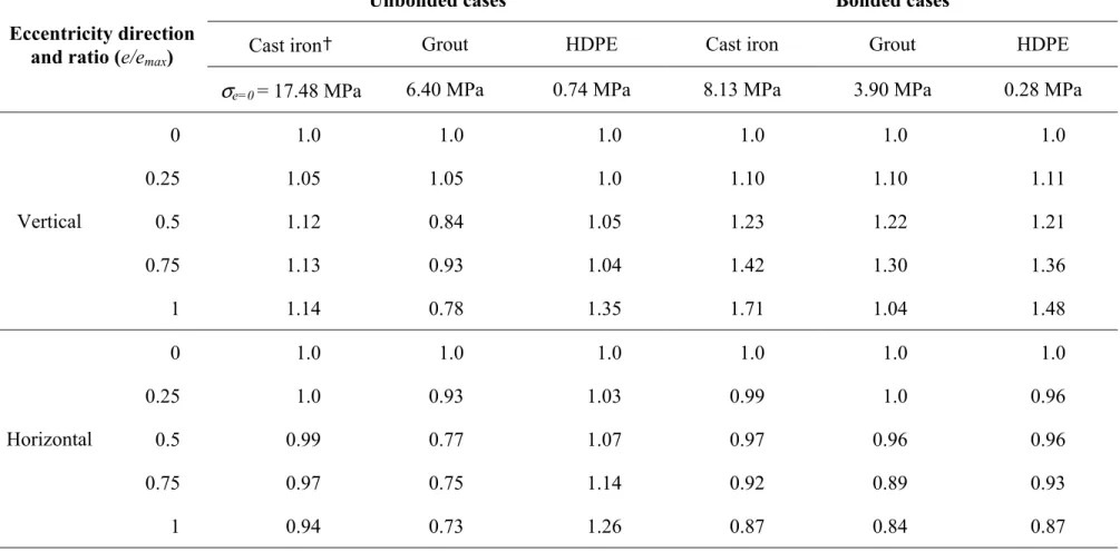
19.7 MPa and 17.0 MPa for the vertical and horizontal eccentricity configurations. In the vertical eccentricity case, the maximum stress occurs at the point of loading that coincides with the minimum thickness of grout (at 12 o’clock position). As the eccentricity ratio increases, the stress at the 12 o’clock position also increases due to the reduced thickness in the grout, whereas the stress at the 6 o’clock position decreases due to the increased thickness in the grout. At an eccentricity ratio of 1, the maximum stress in the cast iron pipe increases by 14% (Table 2). This 14% increase corresponds favourably to the observed increase of 20% in the previous
experimental study. An outcome of that study was a proposed reduction factor of 0.8 applied to pipe strength calculations based on the concentric case (Zhao et al., 2000).
As in the case of vertical eccentricity, the maximum stress in the horizontal eccentricity case also occurs at the point of loading (12 o’clock position). However, unlike in the case of vertical eccentricity, the minimum thickness of grout is at the 9 o’clock position. As a consequence, the maximum stress in the cast iron pipe decreases by 6% when the eccentricity ratio changes from 0 to 1 (Table 2). Comparing the numerical results of horizontal and vertical eccentricities for the same eccentricity ratio of 0.5, the maximum stress in the host pipe with horizontal eccentricity is 13% less than that with vertical eccentricity. Interestingly, in an earlier experimental study (Zhao et al., 2000) the rupture strength of the three-ring pipe samples with horizontal eccentricity (average e/emax = 0.6) was 13% higher on average than those with vertical eccentricity (average
e/emax = 0.5, Table 3). Moreover, rupture of the cast iron host pipe in the samples of sliplined
pipe always occurred in the plane of loading regardless of the direction of eccentricity. That is, the location of rupture did not change with change in the direction of eccentricity. Although direct comparison of the results of this elastic analysis with the experimental results is cautioned
because of increasing non-linearity when the composite pipe approaches its ultimate strength (more discussion later), both results show evidence of the effect of eccentricity and its direction.
The variations of bending stresses along the circumference in the host cast iron pipe are shown in Figure 7 for cases of vertical and horizontal eccentricities. For vertical eccentricity, bending stress (magnitude) increases at the 12 o’clock position in comparison with the concentric case. For horizontal eccentricity, bending stresses decrease at the 12, 9, 6 and 3 o’clock positions. The reduction in stress in the case of horizontal eccentricity may be explained by the fact that the weakest structural point (i.e. the thinnest grout) on the pipe cross-section does not coincide with the applied load. Although the magnitude of this reduction may be of little practical significance, the fact that the maximum stress does not increase with the increase in horizontal eccentricity is indeed significant and could lead to improved design and installation in future sliplining
projects.
Table 2 also shows the normalized (with respect to the concentric configuration) maximum stress ratios in the grout and HDPE pipe rings. The stress ratio increases to 1.35 in the HDPE pipe and decreases to 0.78 in the grout ring, when the vertical eccentricity ratio increases to 1. This increase of stress in the HDPE pipe ring is caused by the discontinuous support of the grout where the annulus is too thin.
The stress ratios in the cast iron and grout rings decrease with the increase in horizontal eccentricity ratio. The stress ratio for the HDPE pipe ring increases to 1.26. These stress ratios show how eccentricity and its direction affect the stresses in the pipe rings of sliplined pipe systems.
3.2. Stresses in bonded case
Figure 8a shows the stress contours in the three pipe rings with bonded interfaces and with a vertical eccentricity ratio of 0.75, and Figure 8b with a horizontal eccentricity ratio of 0.75. Bonding at the interfaces enhances the structural behaviour of the sliplined pipe and, as a result, the maximum stresses are only 11.6 MPa and 7.5 MPa for vertical and horizontal eccentricities, respectively. These values represent 59% and 44% of the maximum stresses calculated in the corresponding unbonded cases. For the concentric case, the maximum stress in the cast iron pipe with bonded interfaces is 47% of that with unbonded interfaces.
Figure 9 shows the circumferential distribution of bending stress in the cast iron pipe in a bonded sliplined pipe with vertical and horizontal eccentricities. Compared to the unbonded case (Figure 7), vertical eccentricity has a larger impact on increasing the magnitude of the maximum bending stress at the 12 o’clock position. For horizontal eccentricity, only a slight increase is seen at the 9 o’clock position. It is evident that horizontal eccentricity has almost no impact on the
maximum bending stress. Table 2 shows that stress ratios in all three pipe rings decrease with the increase in horizontal eccentricity.
For vertical eccentricity, the stress ratio in the cast iron pipe ring increases from 1.0 to 1.71 when the eccentricity ratio changes from 0 to 1. The stress ratio in the grout ring increases with the eccentricity ratio until the latter exceeds 0.75. The stress ratio in the HDPE pipe ring increases to 1.48 at the maximum vertical eccentricity ratio of 1.
Maximum stresses in the HDPE pipe are between 0.74 and 1.0 MPa for the unbonded cases, and between 0.28 and 0.41 MPa for the bonded cases. Thus, the HDPE pipe is subjected to less than 15% of its maximum allowable strength of 11 MPa (diameter to thickness ratio, or DR, of 17 for
the HDPE pipe). Maximum stresses in the grout are between 4.7 and 6.7 MPa for the unbonded cases, and between 3.3 and 5.1MPa for the bonded cases. The tensile stress levels in the grout in the bonded cases represent about 10 - 15% of the 28-day compressive strength of 35 MPa, which is the expected tensile strength and, as such, the grout in the annulus should not crack. On the other hand, cracks may occur in the tensile zones of the grout in the unbonded cases. The
performance of such a sliplined pipe, though an interesting research subject, is beyond the scope of the current study.
Without sliplining, the maximum stress in the cast iron pipe under the same applied load is 24.4 MPa. Sliplining with unbonded interfaces reduces the maximum stress in the cast iron pipe to 17.5 MPa, a reduction of 28%. Sliplining with fully bonded interfaces reduces the stresses even further to 8.1 MPa, a reduction of 67%.
3.3. Ring deflections
Vertical deflections of sliplined pipes with bonded and unbonded interfaces are shown in
Figure 10. For the unbonded cases, deflection decreases as the eccentricity ratio increases either vertically or horizontally. For the bonded case, deflection increases with the increase in vertical eccentricity, but decreases with the increase in horizontal eccentricity. It should be noted that the magnitude of vertical deflection of a concentric pipe with bonded interfaces is about 27% of that of a concentric pipe with unbonded interfaces. These results indicate that eccentricity does not cause an increase in pipe deflection in most cases and that better bonding at the interfaces of a sliplined pipe means less ring deflection.
(3) D y D W ∆ = 149 . 0 ψ
where W is the applied load, ψ the pipe stiffness factor, D the pipe mean diameter and ∆y the
vertical ring deflection. The pipe stiffness factor is a measure of the slope of the load-deflection curves. Figure 11 shows load-deflection curves of bonded and unbonded 3-ring pipes and 1-ring (cast iron only) pipe, together with experimental test data from three sliplined pipe samples (samples 5 to 7, the numbering continues from Figure 2). The unbonded 3-ring pipe is much stiffer than the cast iron pipe alone, and the bonded 3-ring pipe is the stiffest. The behaviour of two of the tested specimens is within the extremes of unbonded and bonded composite pipe. The data for the sample with a horizontal eccentricity of 0.43 (sample 7), however, fall below the line of the unbonded concentric pipe. This suggests that there are other factors, such as the gap at the interfaces and the condition of the host pipe, that come into play. It can be inferred that in practice it is difficult to guarantee bonding at the interfaces of smooth pipes. In addition,
shrinkage that the grout experiences on curing may play an important role on whether bonding is achieved or not. The shear-key type of mechanical anchors would help to improve bonding at the interfaces.
The non-linear numerical analysis reported in this paper is limited to the maximum expected external loads (for the minimum trench width). The principal non-linearity considered is that due to the stick-slip action at the two contact interfaces. Analyses with loads approaching rupture will require the consideration of additional non-linearities such as the initiation and propagation of cracks in the cementitious grout under high tensile stresses and increased material non-linearities of the HDPE, grout and cast iron at high stress levels. Numerical convergence was
not always easy to obtain when only non-linearities due to the contact surfaces were considered, so it is anticipated that numerical convergence will be difficult to achieve under these additional non-linearities.
4. Conclusions
Previously developed closed-form solutions for idealized configurations of unbonded or bonded grouted sliplined pipes were used to validate the numerical (FEM) models. Satisfactory
comparisons between the results of the closed-form and numerical solutions provide reassurance for the analyses of composite pipes with either horizontal or vertical eccentricities. The
numerical models were used to study the effects of bonding at the interfaces and eccentricity between the liner and host pipe on the behaviour of the rehabilitated pipes. The following conclusions can be drawn based on this study:
• The eccentricity between the liner and host pipe in a grouted sliplined pipe, as well as the direction of eccentricity, has a significant impact on the behaviour of the pipe with unbonded interfaces (a pipe-within-a-pipe system). Vertical eccentricity increases stresses in the host and the liner pipe, whereas horizontal eccentricity causes stress increase only in the liner pipe.
• For pipes with bonded interfaces, eccentricity and its direction have an impact on the behaviour of the pipe similar to, with one exception, that on the pipes with unbonded interfaces. The difference is that horizontal eccentricity decreases stresses in all three pipe rings.
• All of the three pipe rings in cases with bonded interfaces are subjected to less stress than in pipes with unbonded interfaces. The bonded and unbonded cases provide the extremes as in the field the situation is likely to fall somewhere between these cases.
• For concentric cases, sliplining with unbonded interfaces reduces the maximum stress in the cast iron pipe by 28% while sliplining with bonded interfaces reduces it by 67%. For other size pipes, this stress reduction may vary. This decrease in stress means an added margin of safety.
• Vertical eccentricity increases the vertical ring deflection of pipes with bonded interfaces, but decreases the vertical ring deflection of pipes with unbonded interfaces. Horizontal eccentricity always leads to a decrease in vertical ring deflection of pipes, regardless of bonded or unbonded interfaces.
5. Design implications
With better understanding of the effect of eccentricity and bonding in sliplined pipe, designers can develop more cost-effective details to take advantage of the grout and the host pipe in sliplining projects. For instances, only vertical eccentricity needs to be controlled in a sliplining installation and horizontal eccentricity may be purposely introduced. Furthermore, profiled liner pipe may be used to increase its bonding with the grout, thus reducing stresses in the host pipe. Properties and geometry of the grout in the annulus can be altered to achieve specific design objectives, e.g., reducing stresses in the host pipe. The longer the host pipe lasts, the longer the service life of the sliplined pipe (Zhao and Daigle, 2001), resulting in savings.
References
• Abaqus®, 2001. Abaqus® Version 6.2 Documents, Hibbitt, Karlsson & Sorensen, Inc., Pawtuchet, RI, USA.
• ACPA, 1992. American Concrete Pipe Association, Concrete Pipe Design Manual. Vienna, Virginia, USA.
• Cast Iron Pipe Research Association, 1952. Handbook of Cast Iron Pipe for Water, Gas,
Sewerage and Industrial Service. Second Edition. Chicago, USA.
• Driscopipe®, 1996. Driscopipe®. Engineering Characteristics. Richardson, TX, USA. • Hickle, J.E., Glasgow, K.L., 1997. Design and installation of large diameter slipliner pipe in
Lakeland, Florida. Proceedings, Trenchless Pipeline Projects: Practical Applications, 8-11 June Boston, Massachusetts, USA, pp. 382-389.
• Marston, A., 1930. The Theory of External Loads on Closed Conduits in the Light of the
Latest Experiments, Bulletin 96. Iowa Engineering Experiment Station, Ames, Iowa, USA.
• McAlpine, G., 1997. Structural rehabilitation of rigid pipes. Proceedings, Trenchless
Pipeline Projects: Practical Applications. 8-11 June, Boston, Massachusetts, USA, pp.
458-465.
• Moser, A.P., 1990. Buried Pipe Design. McGraw-Hill, New York, USA.
• Osako, K., Takahashi, Y., Kitahaasi, N., Akimoto, E., Nakatsui, K., Nakano, M., 1999. Renovation technology and evaluation of load carrying capacity for sewage pipe renewal method. Proceedings, Conference on Infrastructure Regeneration and Rehabilitation,
Improving the Quality of Life through Better Construction, A Vision for the Next Millennium,
28 June – 2 July, Sheffield, UK, pp. 843-852.
• PPI, 1973. Weatherability of Thermoplastic Piping, Technical Report TR-18/73, Plastics Pipe Institute, Washington, D.C., USA.
• Sclairpipe®, 1996. High Density Polyethylene Pipe Systems Design, KWH Pipe, Mississauga, ON, Canada.
• Selig, E.T., Packard, D.L. 1986. Buried concrete pipe embankment installation analysis.
Journal of Transportation Engineering, 112(6), 576-592.
• Spangler, M.G., Handy, R.L. 1973. Soil Engineering. Third Edition. Intext Educational Publishers. New York, U.S.A.
• WRc, 1994. Sewerage Rehabilitation Manual, Third Edition, WRc Engineering, Wiltshire, UK.
• Young, O.C., Trott, J.J., 1984. .Buried Rigid Pipes Structural Design of Pipelines. Elsevier Applied Science Publishers, Essex, UK.
• Zhao, J.Q., Daigle, L., 2001. Structural performance of sliplined watermain. Canadian
Journal of Civil Engineering, 28 (6), 969 -978.
• Zhao, J.Q., Daigle, L., Boudreau, S., 2000. Performance Assessment of HDPE Sliplining of
Gloucester Street Watermain – Final Report, Client Report B-5105.2, Institute for Research
in Construction, National Research Council Canada, Ottawa, ON, Canada.
Table 1. Dimensions and material properties of three rings
Pipe ring Pipe material
Modulus of elasticity (MPa) Poisson ratio Outside diameter (mm) Wall thickness (mm)
Host pipe cast iron1 69,000 0.25 350 20
Grout ring Cement2 21,070 0.2 310 20
Liner pipe HDPE (PE 3408)3 760 0.45 270 17
1 – from Cast Iron Pipe Research Association (1952); 2 – from Zhao et al. (2000); 3 – from Driscopipe (1996)
Table 3. Experimental results on rupture strength (Zhao et al., 2000)
Pipe configuration Number of samples
Average eccentricity ratio
Rupture load (kN/m)
Cast iron alone 4 - 235
3-rings, vertical
eccentricity 8 0.5 313
3-rings, horizontal
Table 2. Ratios of maximum Von Mises stresses with and without eccentricity
Unbonded cases Bonded cases
Cast iron† Grout HDPE Cast iron Grout HDPE
Eccentricity direction and ratio (e/emax)
σe=0 = 17.48 MPa 6.40 MPa 0.74 MPa 8.13 MPa 3.90 MPa 0.28 MPa
0 1.0 1.0 1.0 1.0 1.0 1.0 0.25 1.05 1.05 1.0 1.10 1.10 1.11 0.5 1.12 0.84 1.05 1.23 1.22 1.21 0.75 1.13 0.93 1.04 1.42 1.30 1.36 Vertical 1 1.14 0.78 1.35 1.71 1.04 1.48 0 1.0 1.0 1.0 1.0 1.0 1.0 0.25 1.0 0.93 1.03 0.99 1.0 0.96 0.5 0.99 0.77 1.07 0.97 0.96 0.96 0.75 0.97 0.75 1.14 0.92 0.89 0.93 Horizontal 1 0.94 0.73 1.26 0.87 0.84 0.87
List of Figures
Figure 1. Eccentricity in sliplined pipe: (a) pipe sample, (b) vertical eccentricity, (c) horizontal eccentricity
Figure 2. Load-deflection curves of cast iron pipe samples
Figure 3. Numerical results (e = 0) for model validation: (a) bonded interfaces, (b) unbonded interfaces
Figure 4. Comparison of bending stresses for validation Case A and Case B
Figure 5. A typical FEM mesh used in the analysis
Figure 6. Stress contours for eccentricity ratio of 0.75, unbonded cases, (a) vertical eccentricity, (b) horizontal eccentricity
Figure 7. Circumferential bending stresses in host cast iron pipe, unbonded cases, (a) vertical eccentricity, (b) horizontal eccentricity
Figure 8. Stress contours for eccentricity ratio of 0.75, bonded cases, (a) vertical eccentricity, (b) horizontal eccentricity
Figure 9. Circumferential bending stresses in host cast iron pipe, bonded cases, (a) vertical eccentricity, (b) horizontal eccentricity
Figure 10. Normalized vertical deflection, bonded and unbonded
(a) Host pipe Grout ring Liner pipe tmax W 12 oclock W W 3 6 9 e tmin 12 W 3 6 9 tmin tmax e (b) e: eccentricity t: grout thickness W: applied load (c)
0 50 100 150 200 250 300 350 400 0 0.5 1 1.5 2
Ring deflection, ∆y/D (%)
Load (kN/m) sample 1 sample 3 sample 4 sample 2 FEM
(b) (a)
0 10 20 30 40 50 60 -10 -5 0 5 Stress (MPa) Cast iron pipe
Grout HDPE pipe 20 mm 20 17 Numerical Analytical Validation Case A 0 10 20 30 40 50 60 -30 -20 -10 0 10 20 30 Stress (MPa) Cast iron pipe
Grout HDPE pipe 20 mm 20 17 Numerical Analytical Validation Case B
W (b)
R
R
(a) W W(a) CI pipe bending stresses, vertical eccentricity, unbonded -30 -25 -20 -15 -10 -5 0 5 10 12 o'clock 9 o'clock 3 o'clock 6 o'clock e/emax = 0 e/emax = 1 MPa
(b) CI pipe bending stresses, horizontal eccentricity, unbonded -30 -25 -20 -15 -10 -5 0 5 10 12 o'clock 9 o'clock 3 o'clock 6 o'clock e/emax = 0 e/emax = 1 MPa
(b) R R W (a) W W
(a) CI pipe bending stresses, vertical eccentricity, bonded -30 -25 -20 -15 -10 -5 0 5 10 e/emax = 0 12 o'clock 9 o'clock 3 o'clock 6 o'clock e/emax = 1 MPa
(b) CI pipe bending stresses, horizontal eccentricity, bonded -30 -25 -20 -15 -10 -5 0 5 10 e/emax = 0 e/emax = 1 12 o'clock 9 o'clock 3 o'clock 6 o'clock MPa
0.0 0.5 1.0 1.5
0 0.25 0.5 0.75 1
Eccentricity ratio (e/emax)
Normalised deflection ( ∆ y/∆ ye=0 ) in host pipe vertical eccentricity, bonded case, horizontal eccentricity, bonded case vertical eccentricity, unbonded case horizontal eccentricity, unbonded case Concentric case
Maximum vertical deflection = 0.38 mm, unbonded Maximum vertical deflection = 0.104 mm, bonded
0 10 20 30 40 0 0.1 0.2 0.3
Ring deflection, ∆y/D (%)
Load,
W
(kN/m)
sample 5, vertical eccentricity ratio = 0.48 sample 6, vertical eccentricity ratio = 0.38 sample 7, horizontal eccentricity ratio = 0.43
W W bonded concentric case unbonded concentric case
cast iron pipe alone