DISTRIBUTED ACTIVE CONTROL FOR TENSION STRUCTURES
by
Frank J. Tsai
Bachelor of Science in Civil Engineering Carnegie Mellon University
May 1999
SUBMITTED TO THE DEPARTMENT OF CIVIL AND ENVIRONMENTAL ENGINEERING IN PARTIAL FULFILLMENT OF THE REQUIREMENTS FOR THE DEGREE OF
MASTER OF ENGINEERING
IN CIVIL & ENVIRONMENTAL ENGINEERING
fNG
at
MASSACHUSETTS INSTITUTE OF TECHNOLOGY June 2000
0 2000 Frank J. Tsai. All Rights Reserved.
MASSA CHUSETTS INSTITUTE
OF TECHNOLOGY
MAY 3 0 2000
LIBRARIES The author hereby grants MIT permission to reproduce and distribute publicly paperand electronic copies of this thesis document in whole or in part.
Signature of Author
Certified by
Departmenof Civil and Environmental Engineering May 5, 2000
Jerome J. Connor Prof ssor of Civil and Environmental Engineering Thesis Supervisor
Frank J. Tsai
Submitted to the Department of Civil and Environmental Engineering on May 5, 2000 in Partial Fulfillment of the Requirements for the Degree of
Master of Engineering in Civil and Environmental Engineering
Abstract
The conventional design strategy has been to proportion structures according to a prescribed loading and adjust with structural components and arrangements which are time invariant. This approach produces designs that cannot accommodate, in an effective way, changes in the loading environment. An actively controlled structure dynamically compensates for present state disturbances through a control system integrated on the structure. The control
system reacts to unpredictable conditions and produces a counteractive response. The controller for such a task must possess adaptive and autonomous characteristics. This thesis
investigates the potential of agent technology as the active controller. A model of a cable-supported bridge serves as the test subject for the agents to control vehicular induced deflections. To implement the agent controller, a program, simulating random traffic flow, evaluates the effectiveness and responsiveness of the distributed active control system.
Thesis Supervisor: Jerome J. Connor
Table of Contents Abstract 2 1 Introduction 7 2 Active Control 8 2.1 Monitoring 8 2.2 Controlling 8 2.3 Actuating 9 3 Distributed Agents 10 3.1 Types of Agents 10 3.1.1 Collaborative Agents 11 3.1.2 Interface Agents 11 3.1.3 Mobile Agents 12 3.1.4 Reactive Agents 12 3.1.5 Hybrid Agents 13 3.2 Agent Learning 13
3.3 Knowledge Base Development 13
3.4 Development Phases 14
4 Test Model 16
5 Design ofAgent Displacement Control 18
5.1 Autonomy 18
5.2 Social Ability 18
5.3 Reactivity 19
5.4 Proactivity 19
5.5 Control Algorithm 19
5.5.1 Vertical Elongation of Cables 20
5.5.2 Active Displacement Control Methodology 21
5.5.3 AASHTO Specifications 21
5.5.4 Actuator Applied Displacement 22
6 Deflection Control Simulator 23
6.1 Program Architecture 24
6.1.1 Knowledge Base Acquisition 24
6.1.2 Random Truck Generator 24
6.1.3 Displacement Analysis 25
6.1.4 Actuator Control 25
6.1.5 Movement Simulator 25
Distributed Active Controlfor Tension Structures
7 Test Results 27
7.1 Effects of Active Control 28
8 New Design Considerations 33
9 Conclusion 35 References 36 Bibliography 37 Appendix A 38 Appendix B 45 Appendix C 50
Table of Figures
Figure 1: Linear Actuator 9
Figure 2. Hydraulic Actuator 9
Figure 3. Electromechanical Actuator 9
Figure 4. Intelligent Agent Architecture 13
Figure 5. Knowledge Acquisition Approach 14
Figure 6: Machine Learning Approach 14
Figure 7. Test Model 16
Figure 8. HS 25-44 Truck 17
Figure 9. Deflection Profile of Unit Actuator Force 17
Figure 10. Agent's Control Zone 18
Figure 11: Vertical Elongation 20
Figure 12. Overall Process of Deflection Control Simulator 24
Figure 13. Required Space Between Vehicles 25
Figure 14: Hydraulic Actuator 26
Figure 15. Iteration #10 29 Figure 16: Iteration #20 29 Figure 17: Iteration #30 29 Figure 18. Iteration #70 30 Figure 19. Iteration #80 30 Figure 20. Iteration #90 31 Figure 21: Iteration #130 31 Figure 22. Iteration #140 32 Figure 23. Iteration #150 32
Distributed Active Controlfor Tension Structures
1 Introduction
Historically, the only design paradigm available to structural engineers is passive design. Passive design is based on estimating the worst case loading and selecting a
collection of elements which are arranged to achieve a stable structure. Conventional design methodology ensures that the structural components never exceed the allowable limit when subjected to a stimulus. Upon completion of the design phases, the structure is constructed according to its design specifications with the expectation that it will not fail under any additional loading.
With new developments and advancements in monitor, control, and actuator technologies, actively controlling a passively designed structure has become economically
feasible. The combination of these three components minimizes the effects of a response on the structure. An intelligent system senses changes in the environment and responds
accordingly to maintain the structure's nominal state. Incorporating active means
compensates for the effects of various loading scenarios. Applications of active control for civil structures include eliminating undesired responses from wind and seismic excitations. Deformation is another quantity controllable by intelligent systems.
The objective of this thesis is to address the potential of an intelligent system for controlling displacements. Particularly, this investigation focuses on vehicular induced deformations of a cable-supported bridge. To introduce intelligence into the structure, the distributed agents serve as the autonomous controllers capable of determining the applied deflections and formulating counteractive measures. This thesis first provides an overview of active control and outlines several essential characteristics of agent technology. After developing a controller, a simulator is created to analyze the agent's effectiveness and responsiveness as a distributed active control for tension structures.
2
Active Control
An actively controlled structure compensates for excitations in real time. Sensors and actuators are additions to the conventional structural parameters. The actuators are
controlled by a microprocessor that determines a series of actions to minimize the effects of live loads. Live loads on the structure may come in the form of vehicular, pedestrian, wind, seismic, thermal loads, etc.
An active control system consists of three main components: monitor, controller, and actuator. The monitor component is a data acquisition system that measures external loading on the structure. The intelligent controller then analyzes this set of data and determines a course of action to achieve the desired response. The actuator executes the instructions from the controller through a set of physical devices incorporated on the structure.1
2.1 Monitoring
Monitoring employs devices that measure changes in internal forces, deformations, and/or displacements. Modern sensors are capable of providing extremely precise
measurements at fast sampling rates. Although this thesis is not about sensors, some sensor types applicable for monitoring excitations on tension structures are displacement,
deformation, strain, stress sensors, etc. For the remainder of this thesis, it is assumed that all response quantities needed by the controller are instantaneous and correct.
2.2 Controlling
Once the sensors measure the response, the controller or microprocessor analyzes and evaluates this data through predetermined objectives and algorithms to orchestrate a set of actuators. To actively control a structure, the controller's sampling rate must correspond to the changes in excitation to adequately stabilize the structure. For example, adaptive optics technology for flexible reflectors in earthbound telescopes samples at a rate of 20Hz to compensate for 0.2Hz atmospheric disturbances. During this sampling interval of 50
Distributed Active Control for Tension Structures
milliseconds, the microprocessor must process and compute all necessary data for controlling the actuators.2
Currently, several intelligent control theories exist such as neural networks, fuzzy logic, distributed agent, etc. This thesis investigates the application of distributed agent technology to control cable-supported structures.
2.3 Actuating
The final component of an active control system is the actuator. Actuators apply forces determined by the controller at specific locations on the structure. For civil structures, an ideal actuator is one that can generate a large force in a short time span. These actuators need to deliver forces on the order of meganewtons in Structure
milliseconds.3 Some examples of these devices are Piston Mechanism
hydraulic and electromechanical actuators. Although
these linear actuators are capable of producing large Force forces, they require large amounts of energy to operate.
Figure 14 shows a typical schematic of a linear actuator. Figure 1: Linear
Hydraulic actuators can generate the largest force compared to other actuator types (see Figure 25). Hydraulic actuators operate by forcing fluid in or out of the cylinder to produce a controlled pressure that drives a piston to generate the desired force. A disadvantage of hydraulic actuators is the need for fluid storage system and regulating pumps, which Fi requires continuous maintenance. In addition, hydraulic actuators
have slow response times.
Electromechanical actuators operate by a motor driven piston (see Figure 36). These actuators benefit over hydraulic actuators in size,
gure 2: Hydraulic Actuator
3 Distributed Agents
An intelligent agent is a knowledge-based system capable of performing actions in some environment to meet its design objectives. The agent has control over its actions to complete a task. It interacts with humans or other agents to obtain instructions to solve a problem, but does not blindly obey these commands. Instead, the agents possess the ability to modify information or ask clarification to satisfy the request. These systems sense and react to changes in the environment to determine over time a course of actions to pursue its designed agenda. Intelligent agents must be flexible in that they must possess characteristics of autonomy, social ability, reactivity, and proactivity.
The autonomous agent operates without human interaction and possesses control over its internal state. Given a set of vague specifications, they can determine the best approach to a problem and carry out the actions to solve it. Agents are sociable by interacting with humans or other agents. Communication between agents provides a means of external support to determine solutions. Reactive agents perceive their environment and respond by adapting or changing its present state. Agents must not wait for instructions; rather, they must be goal seeking and take initiatives to resolve problems.
3.1 Types of Agents
Agents possess several attributes. First, agents are either static or mobile. Mobile agents possess the ability to roam about a network to deliver and/or gather information. Secondly, they are either deliberate or reactive. Deliberative agents carry out predefined instructions to achieve a specified goal. They usually contain models of their environment to plan and negotiate with other agents. Reactivity consists of responding to the present state of the environment. Lastly, agents exhibit behavioral characteristics related to autonomy, learning, and cooperation. Autonomy allows the agent to operate without human interaction. Proactiveness is an essential element of autonomy. Proactivity is the ability to take
Distributed Active Control for Tension Structures
changes in their environments. For agents to function as a team, they must cooperate through a communications network.
These attributes and characteristics are grouped to form several types of agents:7 Collaborative Agents Interface Agents Mobile Agents Reactive Agents Hybrid Agents 3.1.1 Collaborative Agents
Autonomy and cooperation are essential components of a collaborative agent. Their emphasis is to negotiate their present state with neighboring agents to mutually agree on a course of actions. These agents may possess learning capabilities, but are limited to remote learning. Typical collaborative agents are static and situated in "time-constrained multi-agent environments."8
A distributed artificial intelligent (DAI) network is the motivation behind a
collaborative system. DAI is "a system that interconnects separately developed collaborative agents, thus enabling the ensemble to function beyond the capabilities of any of its
members."9 DAI provides modularity, which reduces the complexity of the network and
eliminates the need for a central command. In turn, collaborative agents are more flexible and easier to maintain.
3.1.2 Interface Agents
Interface agents focus on autonomy and learning. These agents provide support for the user by learning the user's habits. Interface agents differ with collaborative agents in that interface agents work with the user while collaborative agents collaborate with other
The ideal environments for interface agents are programs that require different users to perform repetitive tasks. This allows the agent to learn and adapt to user preferences. Upon adaptation, these agents develop capabilities to anticipate the users' intentions while suggesting effective measures to facilitate the operation.
3.1.3 Mobile Agents
The third major type of agents is the mobile agent. Designed for roaming large networks, these agents interact with hosts to perform assigned tasks. The World Wide Web is an example of a network in which these agents operate. Their primary objective is to deliver or retrieve information. Characteristics of mobile agents are autonomy and
collaboration. They need to determine where and how to locate the desired information and communicate with other agents to rapidly perform their task.
The mobile agent is advantageous over its static counterpart for search and retrieval operations. For example, suppose one desires to download a certain picture. Instead of downloading a collection of pictures and visually inspecting for the desired image, the agent can go to a specified location, search for the image, and retrieve the picture."
3.1.4 Reactive Agents
Reactive agents differ with other agent types in that they do not possess internal models of their environment. They respond by sensing differences in local data. Each module is autonomous and performs a single task such as sensing, controlling, or computing. They possess low-level communication skills, but up-to-date models of their environment.'2
Benefits of reactive agents are robustness and flexibility. Reactive modules have quick response times and are more tolerant than other systems. These benefits enable adaptability to various types of environments.
Distributed Active Control for Tension Structures
3.1.5 Hybrid Agents
The final type of agent consists of a combination of collaborative, interface, mobile, and reactive types. Hybrids are composed of the strengths from each agent type to
effectively achieve a particular objective. They minimize the deficiencies associated with each agent class.
3.2 Agent Learning
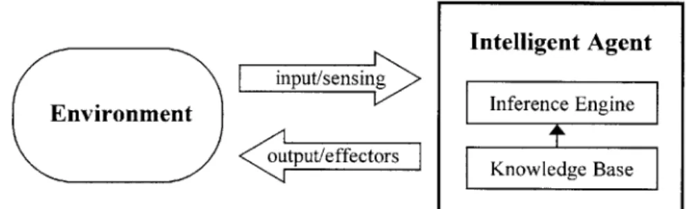
An agent learns if it is capable of acquiring and maintaining knowledge by itself. The typical architecture of a learning agent consists of a knowledge base and an inference engine (see Figure 413). It learns by interacting with its users or other agents. They can also learn from a database or from experience. However, they must be given a starting point or background to bootstrap learning. The initial knowledge need not be complete or correct because the agent will manipulate its knowledge to reflect its current environment.
Intelligent Agent input/sensing
Environment Inference Engine
utput/effectors Knowledge Base
Figure 4: Intelligent Agent Architecture
3.3 Knowledge Base Development
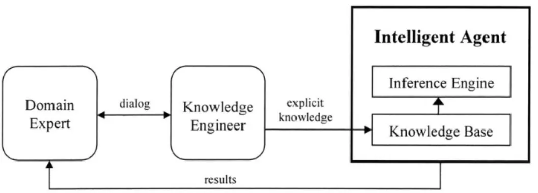
Two major design approaches exist in knowledge base development. The first approach is knowledge acquisition. This approach involves domain experts and engineers to create the knowledge base representation. As shown in Figure 54, the engineer elicits and transfers the expert's knowledge. Once the knowledge base is built, the expert verifies the representation and refines the knowledge through the engineer.
Figure 5: Knowledge Acquisition Approach
The second approach is machine learning. Machine learning focuses on autonomous algorithms to develop a knowledge base. Figure 615 shows an overview of this approach. As part of the agent's learning process, the knowledge base is refined through a learning engine.
Learning Agent
Intelligent Agent
Inference Engine Database - Learning knowledge
Engine Knowledge Base
results
Figure 6: Machine Learning Approach
3.4 Development Phases
Knowledge acquisition and machine learning both consist of similar development phases. The three major phases in developing the knowledge base of an intelligent agent are elicitation, refinement, and reformulation.16 In the first phase, the designer selects a
representational scheme and develops a conceptual structure for the foundation of the agent. The elicited knowledge during this stage is incomplete and inaccurate, but refined and developed in the next phases.
Distributed Active Control for Tension Structures
During the refinement phase, the knowledge bases is debugged and fine-tuned. The incomplete and inaccurate knowledge base of the agents' representations is resolved during this stage. Upon refinement, the knowledge base fully describes the agent's objectives and methods for reaching a solution.
The final phase in developing the knowledge base is reformulation. Although the agent is fully functional by this point, this stage searches for new methods to solve the problem. This may consist of restructuring or reconstructing the knowledge base to achieve maximum efficiency.
The knowledge acquisition approach differs from the machine learning approach in that the former focuses on the elicitation and refinement phases, while the latter emphasizes on the refinement and reformulation phases. In addition, machine learning assumes that there is an existing database, while knowledge acquisition elicits the expert for knowledge. On the other hand, the two approaches are complementary; where one lacks the ability to solve a problem effectively, the other possesses techniques that are more capable.'7 For
example, during the elicitation phase, the engineer may represent the expert's knowledge incorrectly, while the expert may not completely convey their information. These instances result in inefficient development during the elicitation and refinement phases. Machine learning benefits in this area due to its ability to refine and reformulate the knowledge base efficiently and consistently.
Up to now, this thesis has presented the definition of an active control system and the characteristics of an intelligent agent. In the following sections, these concepts are applied to a tension structure. This thesis first proposes a test model representing a cable-supported bridge and then develops an agent controller. Next, applying distributed agent technology, this thesis develops an active controller. Lastly, a program is created to simulate live loads and analyze the agent's effectiveness in actively controlling deflections.
4 Test Model
To examine the effectiveness of an active control system, a test model, Figure 7, representing a 700ft bridge with 27 cable supports spaced at 25ft was created in Structure Analysis Program 2000 Nonlinear (SAP). The cables were arbitrarily fixed at an elevation
1 00ft perpendicular to the deck. Each cable consists of 28 strands of grade 270 high-strength steel. Table 1 shows the material properties for the cables. The model comprises of 57 observation positions (nodes) and 58 possible loading positions. The node spacings are
12.5ft. The deck corresponds to half of an 8-lane bridge. The model represents a beam supported on an elastic foundation.
25f tnode
Figure 7: Test Model
Table 1: ASTM A 416-74 Grade 270
Nominal Diameter (in) 0.60 Nominal Cross-Section (inA2) 0.22 Ultimate Load per Strand (kip) 58.54 Service Load per Strand (kip) 26.34
This model ignores the deflected shape caused by the dead loads of the superstructure because the agents use the deflected profile as a datum to control live load displacements.
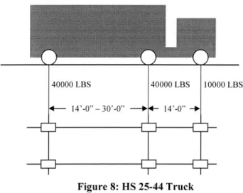
The live loads used in this model are HS25-44 Trucks with a wheel distribution shown in Figure 818. In determining the various positions of the trucks, all trucks are strategically located to produce maximum moment; the center of gravity of loads is at the center of each 12.5ft span. By generating maximum moments, this allows the agents to minimize maximum deflections; therefore, the deformations from all other possible loading conditions will fall within the minimized range.
Distributed Active Controlfor Tension Structures
Figure 8: HS 25-44 Truck
The model also includes unit loads applied at each cable location to imitate the deformation profile caused by an actuator force. Figure 9 shows an example of a unit load applied at the 1 0th cable. Along with the live load profiles, the data obtained from SAP represents the knowledge base for the agents.
Figure 9: Deflection Profile of Unit Actuator Force
5
Design of Agent Displacement Control
The objective of Agent Displacement Control (DC) is to minimize deformations caused by applied loadings. Agent DC achieves this agenda by monitoring the magnitude of the excitation and determining a controlled counteracting force. To accomplish this
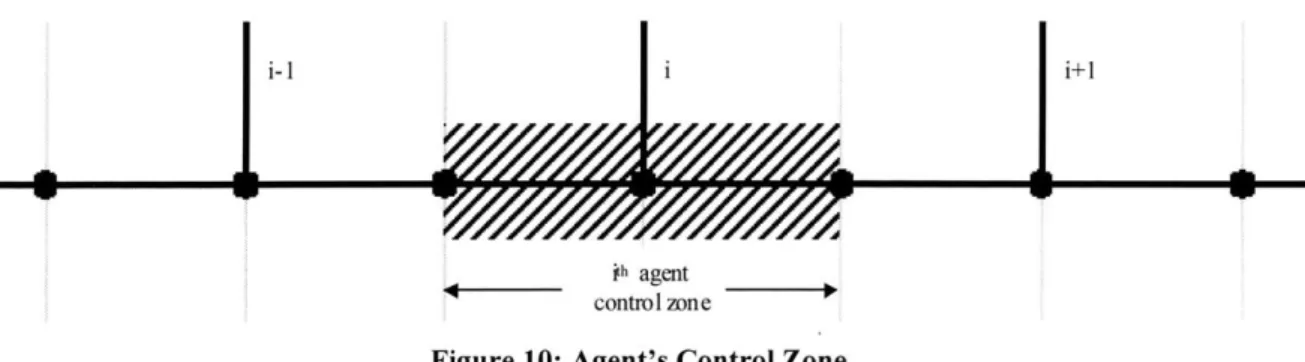
objective, each agent is assigned an effective control zone where they are most influential (see Figure 10). As defined in Section 3, agents must possess the characteristics of autonomy, social ability, reactivity, and proactivity. The design of Agent DC incorporates these characteristics in order for a collection of these agents to function cooperatively. From the several types of agents described, the most applicable type for controlling displacement of a tension structure is the hybrid agent. For this case, the hybrid agent is a combination of collaborative and reactive agent types.
ih agent contm 1 zone
Figure 10: Agent's Control Zone
5.1 Autonomy
Upon activation, Agent DC can operate without human interaction. This autonomous agent possesses control over its internal state. With the implementation of a displacement control algorithm, the agent can develop the most suitable response profile for minimizing displacements. The benefit of a collaborative type is the ability to distribute instructions to other agents.
5.2 Social Ability
Collaboration is essential for a collection of Agent DCs to develop an optimized counteracting displacement profile. In addition, each agent provides a foresight to
Distributed Active Control for Tension Structures
neighboring agents in order to describe specific loading conditions at a certain location. Each agent develops a local displacement profile by sensing applied loads within its control zone and converting this information into displacements. It then compares the local
displacements to its knowledge base to compute the influence on neighboring agents, which allows the collective to produce a total deflected shape of the entire bridge.
5.3 Reactivity
The second agent type incorporated into Agent DC is the reactive type. The benefit of this characteristic is that it produces up-to-date models of its environment. By reacting to applied forces, each agent can apply its knowledge base to analyze the effects at any location throughout the bridge. Therefore, by combining real-time information with the agent's knowledge, Agent DC provides a robust control system that is capable of withstanding any vehicular loading combination.
5.4 Proactivity
The last characteristic of an intelligent agent is proactivity. The agents control a specific zone and their primary local objective is to minimize the deflection within this zone. Adjusting the displacement of each zone influences displacements in other zones; therefore, each agent is constantly analyzing, collaborating, and actuating to achieve its objective.
5.5 Control Algorithm
In determining the control algorithm for this agent, this section first derives an
expression for determining the vertical elongation of a cable. Afterwards, a methodology for displacement control describes a general approach to minimizing deflection. Finally, this methodology is specialized to satisfy the American Association of State Highway and Transportation Officials (AASHTO) specifications.
5.5.1 Vertical Elongation of Cables
in
Figure 11: Vertical Elongation
The vertical elongation of each cable is a function of the tension in the cable, the cable properties, and the cable inclination. As shown in Figure 1119, the cable force Fn due to load Pn at joint n is
(1) Fn = n
sin On
Therefore, the corresponding cable elongation is
Pin
Aln = snO "A
-"E An sin On
(2)
An is the cross-sectional area of the cable and E is the module of elasticity for a linear case. Finally, the vertical elongation due to the cable elongation Aln is
Ali = sn'" 2
0
" E An Sin2 n (3)
Distributed Active Control for Tension Structures
5.5.2 Active Displacement Control Methodology
The displacement u of a beam due to an applied varying load is a function of the location x of the load and the time t. The displacement profile is u(x, t). Suppose the desired profile is u*(x, t). To achieve u*(xt), the displacement uc(x, t) due to a system of controlled forces must be applied to u(x, t). The final profile uj(x, t) is
u. (x, t) = u(x, t) + uc (x, t) (4)
Ideally, one wants u(x, t) u*(x, t). To achieve the final profile, the sensors must be strategically located to monitor maximum displacement, while the locations of the actuators on the structure correspond to the accuracy required to satisfy u*(x, t).
The methodology described above applies to a dynamic case where time is an
essential factor. Dynamic loading conditions such as gusts and seismic forces occur in short time frames. For a quasi-static case, loads are applied relatively slower than in a dynamic condition. As a result, a quasi-static "loading can be approximated as static response."2 0 Quasi-static control is time invariant. Time invariant conditions neglect the effects of time. Once the time variable is eliminated, Equation 4 simplifies to
u * (x) > u(x)+ uc (x) (5)
5.5.3 AASHTO Specifications
Vehicular loading is one form of quasi-static loading. According to AASHTO (10.6.2), the allowable live load deflection2 is
ULL+I <
L
(6)objective of this thesis is not to design a control algorithm according to AASHTO, but to control deflection due to an applied loading. In the former case, the AASHTO multiplicative factors are applied to u(x), if they are a design consideration. For the test model described in Section 4, the length of the span is 25ft; therefore,
. 25
u (x)uLL =0.03125ft (7)
800
The span length is assumed to be the length between cables. This length represents the upper limit of a conservative design span. A more practical length may be 1 00ft, which is the characteristic length.
5.5.4 Actuator Applied Displacement
To determine the displacement necessary to minimize deflection, each agent proactively monitors all deflections within its control zone to computes the average displacement. Rather than exerting a counteracting force equivalent to the greatest magnitude, the average displacement distributes the responsibility to neighboring agents more evenly. This method accommodates more flexibility by allowing the distributed agents to collaboratively develop a profile similar to that caused by the excitation. Another
rationale for using the average displacement is to prevent over actuating, which induces vertical deflection on the structure. The controlled displacement is the average of all deflections within the control zone collected by the sensors.
Zu(x)
U,(X)= L (8)
The variable m is the number of effective local sensors and L is the length of the zone under investigation. As previously shown in Figure 10, the outer most sensors for each zone also provide data for the adjacent control zone; therefore, the agents are highly dependent and must be extremely cooperative.
Distributed Active Control for Tension Structures
6 Deflection Control Simulator
The Deflection Control Simulator (DCS) is a program designed to represent any cable-supported bridge. The benefit of generalizing DCS is to provide flexibility in
analyzing various configurations of cable systems. Appendix A shows the C++ source code for DCS. This flexibility is viable due to the program's dependency on a comprehensive database. The database for the simulator comprises of an rxs matrix, where r is the number of loading positions on the bridge and s is the number of observation points. The existing database consists of influence lines developed by SAP, which represents the deflection
profile due to an applied load. Although the backbone of DCS accommodates flexibility, two additional functions and minor modifications are required to support cable arrangements other than the test model used in this thesis. Currently, functions that vary the cable inclinations and lengths have not been included.
Upon development of the required database, DCS consists of two primary objectives: 1. Simulate random traffic flow
2. Implement agent controller
To satisfy the first objective, the program randomly introduces vehicles onto the bridge and references the database to simulate movement. The simulated movement corresponds to the agents' knowledge base after they have monitored the loads from the sensors. This knowledge base provides a foresight for the agents and allows them to collaborate to control the actuators accordingly.
The second objective is the implementation of the agent's control algorithm. This portion of DCS analyzes the deflection caused by vehicular loads and applies the control algorithm to minimize displacement. Upon completion, DCS returns the deformed profile, the applied actuator deflections, and the total deflected shape at regular intervals.
6.1 Program Architecture
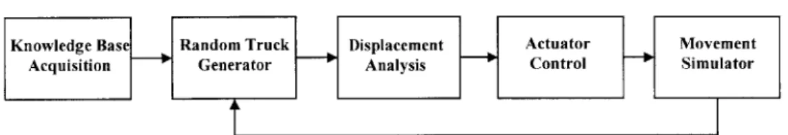
The structure of DCS is divided into five components. Figure 12 shows an overall process of these components, which are:
Knowledge Base Acquisition Random Truck Generator Displacement Analysis Actuator Control Movement Simulator
Knowledge Base Random Truck Displacement Actuator Movement
Acquisition Generator Analysis Control Simulator
Figure 12: Overall Process of Deflection Control Simulator
6.1.1 Knowledge Base Acquisition
For the agents to determine the required counteracting force, they must know the deflected shape due to the truck at its corresponding location. Appendix B represents these influence lines. In this model, sensors placed at every node (12.5ft) detect the magnitude of an applied force caused by the truck driving over the sensor. The controller converts the magnitude into displacements. In addition, the agent's knowledge base contains another set of influence lines, created in SAP, representing the deformed shapes due to unit loads applied upward at each cable (see Appendix C). The agent uses its knowledge base as a multiplier to compute the required force for the actuators.
6.1.2 Random Truck Generator
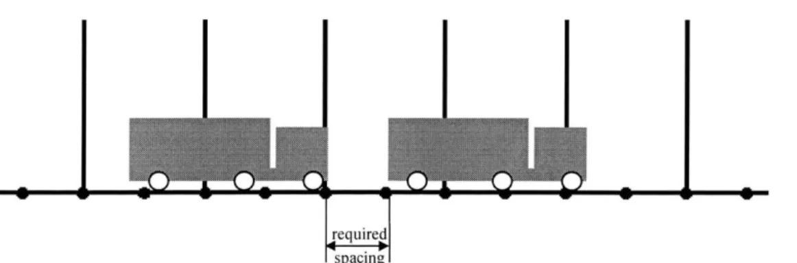
Once DCS receives the agent's knowledge base, a random truck generator simulates random number of HS25-44 trucks entering the bridge for a specified number of cycles. Each cycle consists of 0 to 4 adjacent trucks. The simulator requires a spacing of two nodes between the front end of the vehicle from the current cycle and the rear end of the vehicle from the previous cycle to prevent overlapping, vehicles crashing (see Figure 13).
Distributed Active Control for Tension Structures
Figure 13: Required Space Between Vehicles
6.1.3 Displacement Analysis
After the Random Truck Generator introduces truck(s) onto the bridge, the agents determine the locations of all trucks and apply their knowledge to construct a total deflected profile of the entire bridge. Each agent analyzes their corresponding influence lines and communicates this information with neighboring agents to produce the total deflection.
6.1.4 Actuator Control
The fourth component of DCS controls the actuators. To minimize the deflections caused by vehicular loads, the agents instruct the actuators to generate a set of forces. These forces reduce the average deflection within each agent's effective zone.
6.1.5 Movement Simulator
Lastly, DCS shifts all trucks to the next position on the bridge to simulate vehicular movement. This process continues until all trucks exit off the bridge.
6.2 Boundary conditions
Although Deflection Control Simulator performs properly for its designed objectives, the program was built around several boundary conditions. In generating the traffic flow
With the current analysis, the deflection caused by all vehicular loadings across the four lanes is assumed to be within the tributary area of the actuators. This may not be the case if the bridge consisted of parallel cables along each side of the deck, thereby requiring a distribution factor to reduce the applied loads in each set of cables.
When the actuator exerts a force to lift the deck, the tension in the cables increases. As described in Section 5.5.1, cable elongation is a function of the tension; therefore,
increasing tension will induce additional elongation. This effect can be neglected by using a hydraulic actuator. As shown in Figure 14, the actuator is situated between a spliced cable. By applying a pressure within the cylinder, the piston can control the tension and minimize incremental elongation.
4 Cable
4-- Pressure valve
4- Piston
4--- Cable
Figure 14: Hydraulic Actuator
As stated in Section 5.5.2, by assuming constant vehicular speed and instantaneous monitoring, controlling, and actuating, the time variable could be eliminated. In reality, this variable is an important factor. Although current active control technologies operate on the order of milliseconds, the analysis ignores the effects of a lag time, but this is negligible when compared with the vehicle's speed.
Distributed Active Control for Tension Structures
7 Test Results
The following results describe a 100-cycle simulation of DCS or 158 iterations. Tables 2-7 show a sample output for Iteration #80. Due to the vast amount of data generated by DCS, only one iteration is shown. The output describes the locations of the vehicles, their corresponding deflections u(x), the final profile u/(x), and the controlled displacements uc(x). The boldface nodes represent the location of the cables and the actuators.
Table 2: Iteration #80 -Deflection Profiles at Nodes 1-10 (ft)
1 2 3 4 5 6 7 8 9 10
No. Truck 0 0 0 1 0 0 2 0 0 0
u(x) 0.0000 -0.0195 -0.0314 -0.0453 -0.0560 -0.0671 -0.0538 -0.0371 -0.0267 -0.0322
u,{x) 0.0000 0.0028 0.0103 0.0103 0.0055 -0.0077 -0.0033 0.0027 0.0091 0.0148 uc(x) 0.0000 0.0223 0.0417 0.0555 0.0615 0.0593 0.0505 0.0397 0.0357 0.0469
Table 3: Iteration #80 -Deflection Profiles at Nodes 11-20 (ft)
11 12 13 14 35 16 17 18 19 20
No. Truck 1 0 0 3 0 0 1 0 0 3
u(x) -0.0478 -0.0797 -0.0916 -0.0945 -0.0646 -0.0476 -0.0491 -0.0761 -0.0900 -0.1000
ON4x) 0.0185 0.0057 0.0013 -0.0106 0.0043 0.0151 0.0181 0.0066 0.0056 -0.0028
uc(x) 0.0662 0.0854 0.0928 0.0840 0.0688 0.0626 0.0672 0.0827 0.0955 0.0972
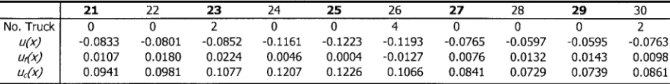
Table 4: Iteration #80 - Deflection Profiles at Nodes 21-30 (ft)
21 22 23 24 25 26 27 28 29 30
No. Truck 0 0 2 0 0 4 0 0 0 2
u(x) -0.0833 -0.0801 -0.0852 -0.1161 -0.1223 -0.1193 -0.0765 -0.0597 -0.0595 -0.0763 u~) 0.0107 0.0180 0.0224 0.0046 0.0004 -0.0127 0.0076 0.0132 0.0143 0.0098 UcA) 0.0941 0.0981 0.1077 0.1207 0.1226 0.1066 0.0841 0.0729 0.0739 0.0861
Table 5: Iteration #80 - Deflection Profiles at Nodes 31-40 (ft)
31 32 33 34 35 36 37 38 39 40
No. Truck 0 0 3 0 0 0 2 0 0 0
u(x) -0.0881 -0.1018 -0.0828 -0.0630 -0.0545 -0.0611 -0.0513 -0.0382 -0.0291 -0.0313 u~) 0.0079 -0.0071 0.0012 0.0091 0.0070 -0.0054 -0.0016 0.0032 0.0047 0.0014
Table 6: Iteration #80 -Deflection Profiles at Nodes 41-50 (ft) 41 42 43 44 45 46 47 48 49 50 No. Truck 1 0 0 1 0 0 2 0 0 3 u(x) -0.0313 -0.0347 -0.0342 -0.0417 -0.0516 -0.0678 -0.0742 -0.0929 -0.0984 -0.1157 uf(x) 0.0031 0.0026 0.0073 0.0088 0.0100 0.0074 0.0140 0.0090 0.0169 0.0143 uc(x) 0.0344 0.0373 0.0415 0.0505 0.0617 0.0751 0.0883 0.1019 0.1153 0.1300
Table 7: Iteration #80 - Deflection Profiles at Nodes 51-57 (ft)
51 52 53 54 55 56 57
No. Truck 0 0 4 0 0 3 0
uNx -0.1234 -0.1426 -0.1341 -0.1337 -0.1077 -0.0762 0.0000
urfx) 0.0186 0.0062 0.0109 -0.0063 -0.0124 -0.0255 0.0000 UcA) 0.1419 0.1488 0.1450 0.1275 0.0953 0.0507 0.00001
7.1 Effects of Active Control
Figures 15-17 displays the 1 0 th 2 0th, and 3Oth iterations. The area enclosed by the dashed lines corresponds to the allowable deflection according to AASHTO specifications. Figure 15 illustrates several trucks entering the bridge. As the traffic flow increase, the agents compensate for the rise in vehicular activity by instructing the actuators to generate additional forces. In addition, the agents rapidly adapt to the sudden changes in flow rate as shown in Figure 17. Although the agents are responsive to various loading conditions, a sudden change in applied force does not immediately affect the deflection profile. This behavior is caused by the influence of adjacent cables. A common profile among the three figures is the steep curvature near the first cable, which causes more fluctuations in the final deflected shape. The agent near the entrance to the bridge receives aid from only one neighboring agent; therefore, its ability to produce a smooth profile is greatly reduced. The frontrunners in Figures 15, 16, and 17 are located at node 10, 20, and 30, respectively. As shown, the majority of influence caused by these loadings is isolated within a range of three cables (75 ft for this model) and the latter portion of the bridge feels no effect.
Distributed Active Control for Tension Structures 0.150 0.125 0.100 0.075 0.050 0.025 0.000 -0.025 -0.050 -0.075 -0.100 -0.125 -0.150 0.150 0.125 0.100 0.075 0.050 0.025 0.000 -0.025 -0.050 -0.075 -0.100 -0.125 -0.150 0.150 0.125 0.100 0.075 0.050 0.025 0.000 -0.025 -0.050 -0.075 -0. 100 -0.125 --- - - - -~ Nodes Figure 16: Iteration #20 Su(x) ~.uf(x) .~UC(x) ) u c(x) -+-u(x) ) VU(x) Nodes Figure 17: Iteration #30
Iterations 70, 80, and 90 are represented by Figures 18, 19, and 20, respectively.
10 1~ ~0 40 4~ 50 55 --- - --- ~---r 1;A() A; 1;( 1; j It.- E.4 Nodes Figure 15: Iteration #10
I
I......
...
...
7d -1 _rF_1 ; 1-I) JA A; 1; A 1; 1; 0 f) ~- -- --- --- --- ~---- --- ~~---~--- -- --1'n I' rj 71 n as n Ali o 55 ragent's collaborative characteristic evenly distributes the loads. The agents reduce the sharp infection points of u(x), which is one advantage of active control. By prescribing a more uniform displacement, the stresses in the superstructure members are also distributed more evenly. In Figures 19 and 20, the traffic pattern changes from a gradual declining flow to a highly random flow. In the former scenario, the agents provide a slow decreasing profile to match the flow rate. In the latter case, the final deflected curve oscillates with the applied shape. The control algorithm is designed to minimize the average deflection for each control zone. As a result, local minimums in uc(x) finalizes to a near zero deflection in u/x).
Unfortunately, points of vertical tangency on uc(x) creates maximum displacements on u(x). In these regions, the agents posses least control due to the lack of sensor data and the
variations between the applied and controlled profiles.
0.150 -.. -...--- -0.125 0.100 0.075 0.050 0.025 - - --- --- (X) - 0.000 -- -.uf(x) -0.025 25 W) 1 4c -0.075 -0.100 -0.125 -0.150 . ... - -. .... ... - ---Nodes Figure 18: Iteration #70 0.150~ ~ ~~ ~ ~~ ~~ ~ ~ ~ ~ - ~ 0.125 0.100 0.075 0.050 S- 0.025--- --- - UX 0.000 ~.Uf(X) S-0.025 1 0 5 ,UC(x) S-0.050 -0.075 -0.100 -0.125 -0.150 -~ ~~ - ~ ~ Nodes Figure 19: Iteration #80
Distributed Active Control for Tension Structures 0.100 0.075 * 0.050 --- --- ---0.000 -u_ Uf(x) -. 2 5 1I s -0 ? 30 3_ 4' 4D V; n 5 - uc(x) -0.050 - ---0.075 -0.100 _ -0.125 Nodes Figure 20: Iteration #90
The final scenarios represent vehicles exiting the bridge (Figures 21-23). Similar to the profiles of the first vehicles, the influence of the last vehicle(s) has slight impact once the loads are distributed over an area of three control zones. Again, the agent near the end of the bridge provides least support due to its one-way communication. This situation is illustrated in Figure 23 where a considerable variation occurs in the final deflection profile. Another contributor to this condition is the carry-over moment. The forces near the ends of the bridge can only be distributed in one direction, resulting in a greater applied load.
0.150 . .____ ... .... . . . - --- . ---_--- --0.125 0.100 0.075 0.050 S0.025--- -_--- ---S 0.000 - %--_j__uf(x) -0.025 1) 10 1s 2 2)S in 15 40 45 6 ...- uc(x) 0-0.050 -0.075 -0.100 -0.125 Nodes Figure 21: Iteration #130
F-0.150 --0.125 0.100 0.075 0.050 0.025 ~~ ~ -- + o 0.000 M-.--uf(x) -0.025 1 i ? ? 3 4uc(x) C -0.050 -0.075 -0.100 -0.125 -0.150Noe Nodes Figure 22: Iteration #140 0.150 ... ... .. - - ---- -0.125 0.100 0.075 0.050 0.025 - -- u(x) 0.000 - uUf(x) -0.025 11 1 5 ? 7 0 1 40 45 63 _ _uc(x) -0.050 -0.075 -0.100 -0.125 -0.150.. --- - ---Nodes Figure 23: Iteration #150
Throughout these figures, all final deflections fall within the allowable region. Although near occurrences arise during dense traffic flows and end conditions of the bridge. When developing the SAP model for this example, the deck elements were not assigned any material properties; therefore, the only deflection resistant elements are the cables. With the implementation of an active control system, the agents reduce the maximum displacements by an average of 94%. As mentioned, the sensors were placed at all cable locations and between spans to detect maximum deflections. In most cases, the agents reduce the
deflections to an order of a hundredth and even a thousandth of an inch. Applying active control with current design specifications creates a redundant system. Therefore, engineers must reevaluate current design methodologies to maximize the potential of an active
Distributed Active Control for Tension Structures
8 New Design Considerations
Current design methodologies consist of passively designing a structure to withstand worst case excitations. By incorporating active control, one can reduce the effects of these excitations. As demonstrated in this thesis, one advantage of an active structure is weight reduction. In the test model used, the actuators generated a system of counteracting forces to eliminate a large portion of vehicular forces felt by the superstructure. When the distributed agents "walked" the vehicles across the bridge, the longitudinal elements experienced only an average of 6% of the applied loads. In turn, an engineer can now redesign structural members according to the new applied forces, which allows for a significant reduction in capacity. Once these sections are reduced, the potential for weight reduction also leads to further savings for the substructure.
When designers applied the passive methodologies, structural members were created to withstand worst case loadings. This method is based on statistical analysis of when the occurrence is likely to happen. In the event that this scenario never occurs, the design
becomes overly conservative and redundant. With active control, rare occasions, to an extent can be ignored because the actuators will accommodate for these instances.
Another advantage of distributed agent control is its ability to decrease the
longitudinal profile of the bridge deck. Minimizing curvature provides an even distribution of cable forces.2 2 When the agents distribute the concentrated forces to neighboring
controllers, this process allows for a reduction in the maximum design capacity of the cables.
Unfortunately, when the actuators increase the tension in the cables to lift the bridge, the generated forces are transferred to other components of the structure. For a suspension cable system, the generated forces increase the overturning moment of the towers and apply additional stresses in the anchorage systems. Engineers must accommodate for the additional reactions caused by the actuators. The test model for this thesis assumed the cables are
the superstructure near the pylons increase proportionally with the created forces. For a cable-stayed arrangement, the stability of the pylons is more dependent on the equal
allocation of cable forces on both sides of the pylon. When the actuators on one side of the pylons generate the desired response, the opposing cables will tend lift the deck from its neutral position. As a result, an increase in negative moment occurs in the counteracting span.
Therefore, although an active system possesses the ability to control external
excitations, it also induces new undesirable effects on the structure. To successfully combine both active and passive designs, one must fully explore the potentials of an active control system while revising the passive design methodology to develop an intelligent structure.
Distributed Active Control for Tension Structures
9
Conclusion
Current design methodologies produce physical systems that are incapable of reacting to changes in the environment, which usually results in an overly conservative design. With developing technologies for civil structures, new design paradigms are incorporating these advancements to improve performance. One such potential is active control. An active control system comprises of a network of sensing, controlling, and actuating devices that dynamically compensate for external disturbances. The sensors quantify excitations for the controller to instruct the actuators to generate a set of reactions to maintain the structure's nominal state. Although several control theories exist, the distributed agents serve as responsive real-time controllers. The agents evaluate the structure's overall behavior by collaborating local data with neighboring agents and cooperating to achieving their design objective. The resulting benefits are foresight and performance.
In a simulator designed to evaluate the agents' capabilities to minimize vehicular deflections, these controllers reduced maximum displacements by 94%. Essentially, the agents "walked" the vehicles across the bridge with minimal disturbances felt by the superstructure. The outcome is largely due to anticipating the vehicle's behavior and counteracting with an even distribution of applied forces. Rather than functioning
individually, the agents collectively accomplish their agenda by compensating for individual weaknesses. For structures where weight is a major factor, a distributed active control system proves to be of great value. As shown, intelligent controllers can provide enormous weight savings and cost reductions. Although this analysis limited the agents to controlling vehicular loads on a cable-support bridge, designers can extend this system to other tension structures and control various excitations, which may lead to further efficient solutions.
As a final note, designers must remember that active control systems are not intended to compensate for bad designs. Active solutions are enhancements to passively designed structures and when appropriately incorporated, will lead to a high performance structure.
References
1 Connor, J.J., and B. Klink, Introduction to Structural Motion Control (MA: MIT, 1999) 430.
2 Utku, S., Theory ofAdaptive Structures: Incorporating Intelligence into Engineered Products (FL: CRC
Press,
1998) 16.
3 Connor 447.
4 Connor 448.
5 Rotork Online. http://www.rotork.com
6 Raco Schwelm. http://www.raco.de
Jennings, N.R., and M.J. Wooldridge, Agent Technology: Foundations, Applications, and Markets (Berlin:
Springer, 1998) p.
8
9 Hugns, M.N., and M.P. Singh, Distributed Artificial Intelligencefor Information Systems (UK: University of
Keele, 1994) p.
0 Jennings 35. 1 Jennings 36. 12 Jennings 39.
13
Tecuci, G., Building Intelligent Agents: An Apprenticeship Multistrategy Learning Theory, Methodology,
Tool and Case Studies (CA: Academic Press, 1998) 2.
14 Tecuci 4. 1 Tecuci 5.
16 Tecuci 3.
17 Tecuci 9.
18 America Association of State Highway and Transportation Officials, Standard Specifications for Highway
Bridges, 1 6th ed. (Washington D.C., 1996) 229.
19 Troitsky, M.S., Cable-Stayed Bridges: Theory and Design (Montreal: Crosby Lockwood Staples, 1977) 179.
20 Connor 488.
2
'AASHTO 24. 22
Gimsing, M.J., Cable Supported Bridges: Concept and Design (Chichester: John Wiley & Sons, 1983) 229.
Distributed Active Control for Tension Structures
Bibliography
American Association of State Highway and Transportation Officials. Standard Specification for Highway Bridges. 16th ed. Washington D.C., 1996.
Connor, J.J., and B. Klink. Introduction to Structural Motion Control. MA: MIT, 1999.
Jennings, N.R., and M.J. Wooldridge. Agent Technology: Foundations, Applications, and Markets. Berlin: Springer, 1998.
Gimsing, N.J. Cable Supported Bridges: Concept and Design. Chichester: John Wiley & Sons, 1983.
Hugns, M.N., and M.P. Singh. Distributed Artificial Intelligence for Information Systems. UK: University of Keele, 1994.
Raco Schwelm. April 2000 <http://www.raco.de>
Rotork Online. April 2000 <http://www.rotork.com>
Tecuci, G. Building Intelligent Agents: An Apprenticeship Multistrategy Learning Theory, Methodology, Tool and Case Studies. CA: Academic Press, 1998.
Troitsky, M.S. Cable-Stayed Bridges: Theory and Design. London: Crosby Lockwood Staples, 1977.
Utku, S. Theory ofAdaptive Structures. Incorporating Intelligence into Engineered Products. FL: CRC Press, 1998.
Distributed Active Control for Tension Structures
7*
Deflection Control Simulator
#include <iostream.h> #include <iomanip.h> #include <fstream.h> #include <time.h> #include "OpenFile.h"
const int positions = 58; // Number of Truck Locations on Bridge
const int nodes = 57; // Number of Nodes on Bridge
const int cables 27; // Number of Cables on Bridge
const float E = 4176000; 7/ Modulus of Elasticity for Steel (k/ft^2)
const float A = 0.0422; // Cross-Sectional Area of Cable (ft^2)
const float L = 100; // Length of Cable (ft)
// Function Prototypes
void GetHSLoading(ifstream& infile, float HS[][]);
void GetActuatorData(ifstream& infile, float UnitAct[][]);
void GetData(int& num);
void AddTruck(float loc[], int random);
void Loading(float TotalLoads[], float HS[][], float loc]);
void Actuator(float TotalLoads[], float act[][], float appdelta[]);
void Move(float TotalLoads[], float loc[]);
// Simulate Random Number of Trucks Driving Through a 700ft Bridge
void main()
ifstream HSData, ActData; fstream outfile;
int r,c,cycles, iteration, randomtrucks, truckcyc; float Total[nodes], Applied[nodes], Location[positions]; float Load[positions+l][nodes], Actuate[cables+l][nodes];
// Initialize arrays
for (c=l; c<=positions; c++)
Location[c] = 0;
for (c=l; c<=nodes; c++)
Total[c] = 0;
// Get loading data and agent knowledge base
OpenFileForReading("File of Loadings? ", HSData);
GetHSLoading(HSData, Load);
OpenFileForReading("File of Unit Actuator Forces? ", ActData);
GetActuatorData(ActData, Actuate);
// Get number of cycles and span length
GetData(cycles);
out file.open("output.xls",ios::out);
// Simulate bridge loading until last truck is off the bridge for (r=l; r<=(iteration); r++)
// Add truck(s) for desired number of cycle(s)
if (r<=truckcyc)
randomtrucks = rand()%5;
AddTruck(Location, randomtrucks);
7/ Loading the bridge
Loading(Total, Load, Location);
// Output truck position(s) and corresponding loads
if (r == 1)
for (c=l; c<=nodes; c++)
out file << setw(30) << c;
outfile << endl;
out file << "Iteration#" << r outfile << endl;
for (c=l; c<=positions; c++)
outfile << setw(30) << Location[c];
outfile << endl;
for (c=l; c<=nodes; c++)
out file << setw(30) << Total[c]; outfile << endl;
// Actuate countering loads
Actuator(Total, Actuate, Applied);
// Output deflection after actuating
for (c=l; c<=nodes; c++)
out file << setw(30) << Total[c]; outfile << endl;
// Ouput total change in deflection and required force
for (c=l; c<=nodes; c++)
out file << setw(30) << -Applied[c]; out file << endl;
// This section is blocked out unless the cable forces are desired
/* for (c=l; c<=nodes; c++)
if (c%2 != 0)
out-file << setw(30) << -Applied[c]*E*A/L; else
out file << setw(30) << 0; outfile << endl;
*/
7/ Move truck(s) to next position
Distributed Active Controlfor Tension Structures
// Add New Truck(s) to Bridge
void AddTruck(float loc[], int random) {
float numtrucks;
Trucks cannot overlap (loc[2]==0 && loc[3]==O)
// Randomize number of switch (random) case 0: numtrucks break; case 1: numtrucks break; case 2: numtrucks break; case 3: numtrucks break; case 4: numtrucks break; loc[l] = numtrucks;
trucks entering bridge
0; =1; = 2; = 3; = 4; } else loc [1] = 0;
// Load the Bridge with Corresponding Trucks
void Loading(float TotalLoads[], float HS[] [nodes], float loc[]) int i,j;
// Summing all loads on the bridge
for (i=1; i<=positions; i++)
for (j=l; j<=nodes; j++) TotalLoads[j] += HS[i][j]*loc[i]; // if { }
// Actuator Algorithm
void Actuator(float TotalLoads[], float actdelta[] [nodes], float appdelta[)
int i,j,n;
float AveDelta,AdjustFactor;
// Initialize array
for (j=l; j<=nodes j++)
appdelta[j] = 0;
// Determine and apply actuator force for all cables
for (i=l; i<=27; i++)
/7 Determine average deflection within effective cable zone
n = 2*i+1;
AveDelta = (TotalLoads[n-l]+TotalLoads[n]+TotalLoads[n+l1])/3;
// Force factor for minimizing deflection
AdjustFactor = AveDelta/actdelta[i][n];
// Apply actuator force and readjust bridge deflection
for (j=l; j<=nodes; j++)
TotalLoads[j] -= actdelta[i][j]*AdjustFactor;
appdelta[j] += actdelta[i][j]*AdjustFactor;
// Move All Trucks on the Bridge
void Move(float TotalLoads[l, float loc[])
int i,a, temp[positions];
// Initialize array
for (i=1; i<=nodes; i++)
TotalLoads[i] = 0;
7/ Shifting all trucks
temp[l] = 0;
for (a=l; a<positions; a++)
temp[a+1] = loc[a];
for (a=1; a<=positions; a++)
Distributed Active Control for Tension Structures
// Get HS25-44 Loadings from Data File
void GetHSLoading(ifstream& infile, float HS[ [nodes])
int i,j;
for (i=l; i<=positions; i++) for (j=1; j<=nodes; j++)
infile >> HS[i] [j];
infile.close ();
// Get Unit Actuator Forces from Data File
void GetActuatorData(ifstream& infile, float UnitAct[ [nodes])
int i,j;
for (i=l; i<=cables; i++)
for (j=l; j<=nodes; j++)
infile >> UnitAct[i][j];
infile.close ();
// Get Number of Cycles
// Each Cycle Represents 0 to 4 Trucks Entering Bridge
void GetData(int& num)
{
cout << "\nTotal Number of Cycles:
cin >> num;
/ *
OpenFile. h
#include <iostream.h> #include <fstream> #include <string>
void OpenFileForReading(string message,ifstream &)
OpenFile. cp
*7/
#include "OpenFile.h" #include <iostream> #include <iomanip>
const int MAXFILENAME = 30;
//declarations
void OpenFileForReading(string message, ifstream& infile)
char filename [MAXFILENAME]; do
cout << message;
// ditch any lingering carraige returns, blanks, etc.
cin >> ws;
cin.getline (filename,MAXFILENAME); infile.open(filename, ios::in);
if (infile.fail())
cout << endl << "INPUT FILE COULD NOT BE OPENED!" << endl;
infile.clear();
} while (!infile.is open();
Distributed Active Control for Tension Structures