Publisher’s version / Version de l'éditeur:
Vous avez des questions? Nous pouvons vous aider. Pour communiquer directement avec un auteur, consultez la première page de la revue dans laquelle son article a été publié afin de trouver ses coordonnées. Si vous n’arrivez pas à les repérer, communiquez avec nous à [email protected].
Questions? Contact the NRC Publications Archive team at
[email protected]. If you wish to email the authors directly, please see the first page of the publication for their contact information.
https://publications-cnrc.canada.ca/fra/droits
L’accès à ce site Web et l’utilisation de son contenu sont assujettis aux conditions présentées dans le site LISEZ CES CONDITIONS ATTENTIVEMENT AVANT D’UTILISER CE SITE WEB.
Building Note (National Research Council of Canada. Division of Building
Research), 1964-04-01
READ THESE TERMS AND CONDITIONS CAREFULLY BEFORE USING THIS WEBSITE.
https://nrc-publications.canada.ca/eng/copyright
NRC Publications Archive Record / Notice des Archives des publications du CNRC :
https://nrc-publications.canada.ca/eng/view/object/?id=32ec8727-ac7f-4dba-a5e5-a971afe34e5e https://publications-cnrc.canada.ca/fra/voir/objet/?id=32ec8727-ac7f-4dba-a5e5-a971afe34e5e
NRC Publications Archive
Archives des publications du CNRC
This publication could be one of several versions: author’s original, accepted manuscript or the publisher’s version. / La version de cette publication peut être l’une des suivantes : la version prépublication de l’auteur, la version acceptée du manuscrit ou la version de l’éditeur.
Access and use of this website and the material on it are subject to the Terms and Conditions set forth at
Absorption of diffuse sound by a strip or rectangular patch of
absorptive material
Ser
TKL
B92
no.
44
c . 2 B D GABSORPTION
OF
DIFFUSE
SOUND BY
A
STRIP
O R
RECTANGULAR PATCH
OF
ABSORPTIVE MATERIAL
T. D.
Northwood
-
.
' ,,
/-'-.
-
- >. .-
.DlYlSlON OF BUlPDlNG RESEARCH N A T I O N A L RESEARCH COUNCIL OTTAWA, C A N A D A
~ Z S O R P T I O N
OF DIFFUSE
SOUND B YA
STRIP ORRECTANGULAR PAT
G H
O F ABSORPTIVEMATERIAL
T .
B.
NorthwoodIn a recent paper, some calculations were presented of
the effective absorption coefficient of a s m a l l a r e a of sound absorbing m a t e r i a l s e t in an otherwise reflecting surface. The r e s u l t s have bearing particularly on the standard reverberation-chamber method
for measuring the sound absorption coefficients of materials.
The
published r e s u l t s w e r e primarily for illustration,
in
a discussion ofreverberation chamber measurements; this note, prepared for potential u s e r s of the calculations, presents the complete s e t in a m o r e usable f o r m than was possible i n publication.
The theoretical basis for the calculations reported h e r e i s
outlined in an e a r l i e r paper (copy attached a s Appendix
A ) . A
discussion of the final results, particularly as they affect r e v e r b e r a - tion chamber t e s t s i s given in the second paper (copy attached a s
Appendix
B).
The
main body of this report will consist of a fewnotes on the computations and tables and graphs of the r e s u l t s .
NOTES ON COMPUTATION PROCEDURES
The detailed program was s f course conditioned by the
available computer facilities.
In
this instancea
Bendix (3-15computer was used and the programming was done with the aid of
the interpretive routine Intercom 1000. As the machine memory
was not capable of taking the whole program at once, the calculations w e r e done in three stages, employing an auxiliary magnetic tape
storage for intermediate results.
The calculation to be performed ( s e e Appendix
B)
wasfor a n adequate range of values of conductance ratio
g ,
susceptanceratio b, and ka, which is a measure of the size of the absorbing
material (k = 2 IT/A and a = cld/(c
+
d), where c and d a r edimensions of a rectangular patch). Analytically derived formulae
a r e available for ka = 0 and ka = 0 0 ; it i s desirable to make cal-
culations for enough values of ka to permit reliable estimates throughout the intermediate region.
It is a necessary preliminary to calculate the quantities
A
andB
for each combination of8,
4,
and ka, using the equations:ka s i n +
cos(x sine)
Jo
(x)dx- - x cos(x sine)Jo(r)dx,
The main integration (Equation 1) was a straightforward
matter.
A
double integration was done, employing Sirnpson1 s one-third rule for the two variables
8
and+.
Intervals ofv/12 were
used for both variables. This integration was readily carried out for a good range of values of g and b.
The major task was the calculation of A and B (Equations
2 and
3)
which involve8 ,
+
and ka in a complicated relation. Theuse of constant intervals of
8
and4
for the final integration necessitateda different set of integration intervals for each value of ka sin+. Hence,
a complete integration was done for each combination of ka,
8
and+.
Thus for each value of ka there were 4 2 calculations (plus
6
zero valuesfor
4
=
0).Though the integral B is finite throughout the interval the
integrand t e r m
N
( x ) becomes infinite at x = 0 . This difficulty was0
disposed of by usrng an analytical solution for the integration in the
interval 0
<
x<
0.02; in this range cos (x sin8 )
can be taken to beunity and the integral i s greatly simplified.
Thus,
for example,(G. N.
Watson, Treatise on the Theory of Bessel Functions, 2ndEdition, Cambridge University P r e s s ,
1958, p.
752)'3
-
Note:T h e
function No i s the Bessel function of the second kind,designated
Y
by some writers (e. g. Watson, Jeffreys)0 . 0 2 0 . 0 2
S
cos (x s i n e ) N (x) dx 2S
No (x) dx-
-
.06400 0 0 0 0.02 andS
xNo
(x)dx
= [ x N ~ ( x ) ] ~ =-.
000576 0As a m a t t e r of convenience the s a m e procedure was used a l s o for
Jo(x) and x
J
(x).
0
To
investigate the variation with ka, ten values of thisp a r a m e t e r , ranging f r o m 2 to 50 w e r e selected. Because of the oscillatory nature of the integrand t e r m s , f a i r l y s m a l l increments
had to be used throughout, with
the
r e s u l t that the calculations forl a r g e ka w e r e r a t h e r lengthy.
The t h r e e s t a g e s of the calculation w e r e a s follows:
Stage
1.
Calculate and s t o r e on magnetic tape a l l the requiredvalues of
J
(x), xJ
( x ) ,N ~ ( x )
andx
N(x).
0 0 0
Stage 11. Calculate and s t o r e on magnetic tape a l l required values
of A,
B
and( A ~
+
B~).
Stage 111. Calculate for g = 0. 1 to 1 . 0 , and b
=
- 0 . 4 to $- 0. 5, f o rten values of ka f r o m
2
to50.
RESULTS
All the calculated values of
c,
including those analyticallyderived for ka =r 0 and ka = 00, a r e given i n Tables I , I I and
I 1
I .The data a r e a l s o presented in perhaps m o r e useful f o r m
i n F i g u r e s 1 to
14.
E x t r a c u r v e s have been derivedby
interpolationf r o m the calculated data, to facilitate e a s y use of the graphs.
The
standard r e v e r b e r a t i o n room t e s t
(ASTM
C423-61T) employs arectangular sample a r e a ,
9
ft by 8 f t , and six standard frequencies,125, 250, 550, 1000, 2000, and 4000 cycles/sec. Values of ka for
these conditions a r e given
in
TableI
V.
F o r the m o s t p a r t i t i s possible to use one of the rounded values of ka without significant e r r o r , but two e x t r a curve sheets ( f o rka
=2.95
and ka =94.4)
USE
OF
THE
CURVES
'Irlae
@alculations givethe
effective a b s o r p t i ~ n coefficientof
any
size of rectangular patchof
locally-reacting material, s e tin
an
otherwise perfectly reflecting plane and exposed toa diffuse
sound i i e l d .
The
usermust
first considerhow
closely thesecorn-
ditions a r e met.
Hard
plaster, concrete o r masonry surfacesprovide
a
good approximation to perfect reflection;m a n y
denseporous materials
o r
perforatedor
fissured tiles mounted directly-against
a wall are approximately Locally-reacting; i f the absorbingsurface is s e t out
f r o m
the reflecting surface rather than flushwith
it,
an e r r o r might be expected i f the disglaee~nent it; greaterthan
ahout
a quarter-wavelength.'Rhe
most;
difficult condition isthe diffuse
solaudfield.
Even
in
reverberationroams,
in whicha.
high
degree of diffusion isa
majorobjective,
there is awide
scatter
in results
(seeAppendix
B)
whishcan only
be attributedto diffusion problems.
Subject ts
the
above limitations,a
caleulatios canbe
made if the
cwmplex
a,dmittanceratio
is b o w nfor
the material.This
can be derived from the compleximpadaace
ratiou ~ i n g
equations
4
and5:
I f the acoustic impedance
ratio is denoted by
z
= r+
j xand the
admittance ratio isy
=
g-
ib,
Alternatively, it
can
beobtained
directly f r o mimpedance
tubemeasurements. The m i n i m u m / m a x i ~ ~ ~ ~ r n
ratio
andthe distances
from sample face to f i r s t and second minima
are
determinedin
the
usual w a y
( s e eM T M
C-384).
Then Figure15
may be usedt~
obtain
the
conductance and susceptance ratios.If
the required values f
Ba
falls between
twoof the given
quantities it is usually sufficient t o determine 3 s
for adjacent
ka
values
and interpolate between them. For
values
of
ka i r e a t e rthan
50 a similar procedure m a y be used, but
using the
reciprocals ofka
(e.
g.
interpolating between l/ka=
0 . 0 2
andl/ka
=
0).*
The discrepancy in sign a r i s e s from the different origins of the
TABLE
I
TABLE I I
EFFECTIVE
ABSORPTION COEFFLCENTS FOR
-
ZERO
SUSCEPTANCE RATIO,
bTABLE 111
TABLE
I V
LlST
O F
DATA FOR CALCULATLNG E F F E C T I V E
ABSORPTION
O F
STANDARD SAMPLE AT STANDARD FREQUENCIES
( P E R
ASTM C 4 2 3
-
61
T )
S U S C E P T A N C E R A T I O , b
0.5 0 . 4 0. 3 0. 2 0 . 1 - 0 + 0 . 1 0. 2 0. 3 0 . 4 0 . 5 S U S C E P T A N C E R A T I O , b
0.5
0.4
0. 3 0. 2 0 . 1 -a
t 0 . 1 0 . 2 0 . 3 0 . 4 0 . 5S U S C E P T A N C E R A T I O , ti
0. 5 0. 4 0. 3 0. 2 0 . 1 - 0 + 0 . 1 0. 2 0. 3 0. 4 0.5 S U S C E P T A N C E R A T I O , b
0 . 5 0 . 4 0. 3 0. 2 0 . 1
-
0 + 0 . 1 0. 2 0. 3 0 . 4 0 . 5 S U S C E P T A N C E R A T I O , bBk? 3/02 - 5
0 . 5 0 . 4 0. 3 0. 2 0 . 1 - 0 + 0 . 1 0. 2 0. 3 0 . 4 0. 5
S U S C E P T A N C E R A T I O , b
0. 5 0. 4 0. 3 0. 2 0 . 1
-
0 + 0 . 1 0. 2 0. 3 0. 4 0.5 S U S C E P T A N C E R A T I O , b0.5 0 . 4 0. 3 0. 2 0 . 1
-
0 + 0 . 1 0. 2 0. 3 0. 4 0.5S U S C E P T A N C E R A T I O , b
k a = 32
0.5 0 . 4 0 . 3 0. 2 0 . 1
-
0 + 0 . 1 0. 2 0. 3 0. 4 0 . 5S U S C E P T A N C E R A T I O , b F l C U R E 11 k a = 50 ( S T D S A M P L E A R E A A T 2000 c i s )
0 . 5 0 . 4 0. 3 0. 2 0 . 1 - 0 + 0 . 1 0. 2 0. 3 0. 4 0 . 5
S U S C E P T A N C E R A T I O , b
0 . 4 0. 6 C O N D U C T A N C E R A T I O , g
A P P E N D I X
AReprinted from T H E JOURNAL OF T H E ACOUSTICAL SOCIETY OF AMERICA, Vo1. 31, NO. 5, 595-599, May, 1959
Capyright, 1959 by the Acoustical Society of America. Printed in LI. S. A.
Absorption of Sound by
a
Strip of Absorptive Material in a Diffuse Sound Field*
T. L). N O R T ~ ~ W O ~ D , h'f. T. CRISARU,~ AND &I. A. EDCO COX$
Digision of Bt~ildir~g Kcsearcli, Nalicmal Researclr Coztncil, Oiiuwu, Caxuda (Received February 5, 1959)
The random incidence sound absorption coefficient is calculated fr r a narrow strip of absorbing material set in an otherwise reflecting plane. The assumptions made are that the material is of the locally reacting type, with 8 real normal admittance. The effect of an imaginary component of admittance is discussed
qualitatively.
The results show the increase in absorption coe5cient that occurs a t small widths due to diffraction. Consideratioa is also given to the absorption of recta.ngular patches having both dimensions in the diffraction range. The standard reverberation room measurement of sound absorption is examined.
INTRODUCTION
T
HE performance of a sound absorbing material is generally determined by placing a sample in a reverberation room and observing its effect on the reverberation time in the room. The sound absorption coefficients for the material are then calculated from the two sets of reverberation times using the Sabine or Norris-Eyring reverberation formula. The coeffi- cients thus obtained may Le used with reasonable success in the many acoustical problems for which the reverberation theory is valid. There is, bowever, one notable weakness in the procedure. The sample that can conveniently be tested in existing reverberation rooms is a relatively small patch the dimensions of which are a few wavelengths or less, depending on frequency. In this region cliffraction effects may be expected to occur, resulting in measured absorption coefficients that depend on the dimensions of the sample. I t is desirable to know the extent of this effecl, and to be able to correct for it in typical applications.3fost of the laboratories that operate reverberation rooms have made experimental studies of the effect of sample size. Of the published materialI4 the most
--
*This paper is a contribution of the Division of Ruildi~g Research, National Research Council, Canada, and is published with the approval of the Director of thc Division.
t Now a t Palmer Physical Laboratory, Princeton University. $ Now a t KCS Data Control, Toronto, Ontario.
V. L. Chrisler, J. Research Natl. Bur. Standards 13, 169 (1934).
Paul Sabine, J. Acoust. Sac. Am. 6, 239 (1935).
aNorris, Nkon, and Parkinson, J. Acoust. Sac. Am. 9, 234
(1938).
comprehensive is Chrisler's well-known paper. There are difficulties, however, in studying an adequate range of sample sizes within the confines of cstablished reverberation room techniques. In particular, it is dificult to approach the limiting value corresponding to an infinite area. To achieve the diffuse field which is basic to the reverberation theory, the total absorption in the room must not become too high; and to avoid effects peculiar to the roorn boundaries the sample niust not approach closer than about half a wavelength to an edge or corner of the room? For very small samples, the only difficulty is in producing a nleasurable change in the absorption in the room. One nlay avoid this difficulty by using several small samples, but there will probably be an interaction unless they are spaced several wavelengths apart.
One of the earliest theoretical studies of the problem was by Pellam,5 who developed an expression for the absorption of an infinitely long narrow strip for plane waves incident in a direction perpendicular to the axis of the strip. Levitas and Lax6 also investigated this problem, and set up a variational method applicable to more complicated cases, one of which will be dealt with in this paper. Both of these studies apply to a material of the "locally reacting" type the behavior of trrhicll can be specified by its specific normal impedance or admittance.
". V. Waterhouse, J. Acoust. Sw. Am. 29, 544-547 (1956). J. R. Pellam, J. Acoust. Sac. Am. 11,396 (1940).
= A . Levitas ant1 M. Lax, J. Acoust. Soc. An]. 23, 316-322
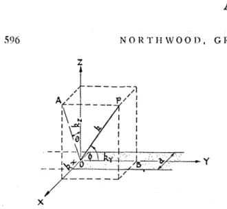
FIG. 1. Geometrical formulation oi the problem. The strip lies
in the X Y plane, its center line coitlciding with the Y axis. O P
is the propagation vector k for a typical incident plane wave, with
components k,, k,, and k,. OA is the quantity referred to in the
text as K = (k?-kv2)) = k sin+.
Cook7 has considered both he strip and the circular patc11, and has worked out the latter for both normal and random incidence. But this was achieved a t the expense of assuming a piston absorber, the whole surface of ~ v h i ~ h must act in phase, and except for normally incident sound the absorption coefficient must approach zero for large dimensions. Hence the results for random incidence do not throw much light on the practical case. Alore recently CookS has been able to generalize the method by replacing thg piston absorber
with one in which the surface motion may be specified by an appropriate Fourier expansion. The components nlay be selected to fit the boundary condition of a
ure will be developed
R. K. Cook, J. Acoust. Soc. Am. 29,334-329 (1957).
a R. K . Cook, J. Acoust. Soc. Am. 30, 697 (A) (1958).
admittance ratio. The solution is developed for propa- gation in the X Z plane, but it is shown that incidence out of the
X%
plane may be dealt. with by considering only the component normal to theI7
axis (since the absorption of the material is assumed to depend only on the normal impedance).THEORY FOR OBLIQUE INCIDENCE
Levitas and Lax work out the complete solution for normal incidence only. The more general case is readily evaluated by retaining the angular variable in their
Eq. (36) and thereafter.$ Incidence in the XZ plane is
first considered. Equations (38) and (49) retain the same form except that the integrals A and B are modified by a cos(x sine) factor relating to the normal impedance assumption [see Eq. (100) below].
Thus
al/aQ= ltll2A/~e(tl) (38) and
where U S , o,, and a t are, respectively, the scattering,
absorption, and total cross sections (per unit length).
FIG. 2. Absorption coefficient of infinite strip of width a
and real admittance ratio 6.
3 Equations numbered below (100) are from Levitas and Lax
. . . . . - -. - . ...
A - 3
S O U N D A I I S O W P T I O N B Y A S'I'IZII' 507
Combining these, pulting q=6+iE,
*
and 4a6 klz ninthB=
[
cos(r sis0)No(~)dr u'(*)=1 + ( 6 ~ + f ' ) ( ~ ~ + f l ~ ) + 2 ( 8 ~ - [ ~ ) . 1 ,.I;" %in+
Following Levitas and Lax, this espression is modified" to take account of iricide~lce out of the X Z plane by replacing q with an effcctive admittance ratio
This anlounls to considering only the component of the incideilt wave parallel to the S Z plane for calculati~lg both incident and absorbed energy. To obtain the absorption cross section, defined as the energy absorbed from an incident wave of unit intensity, the expression must be multiplied by sit:+ to restore the variation of incident energy with angle 4. The limits of the integrals
A and R are also affected since d= &a= $ka sin@. With these changes, the absorption cross section is expressed
as a function of fl and
+
where . .
This is the energy absorbed by a unit length of strip for an incident plane wave of unit intensity.
Random Incidence Absorption Coefficient
Consider now an incident sound field consisling of a uniform distribution of such incident waves (of unit intensity) for all angles in the hemisphere. The incident energy density on the strip for one such wave will be c o d sin+. The energy per unit area absorl~ed from such a wave will 11e aU(0,4)/a. The random incidence absorp- tion coefficient is obtained by integrating each of these quantities over the hemisphere and forming the quotient (total energy absorbed per unit area)/(total incident energy density). The denominator is just x/4, so that
When a approaches zero, A and B also approach zero and Eq. (101) becomes 60=86. This is the value usually obtained for a strip or patch of absorbing ma.teria1 small enough that it does not significantly alter the sound field a t the otherwise reflecting surface. When the strip width becomes very large R -+ 0 and
2
A + (1-sine)-;= l/cosO. Equation (101) then reduces
tc the more syn~nletric form
Noting that the term cos6 sin#= cosl, where I is the angle of incidence, the integral is readily evaluated by rotating the coordinates so that the polar axis is
normal to the surface. The result is
0 0.2 0.4 0 . 6 0.8 1.0
E
I M A G I N A R Y PART OF A D M I T T A N C E RATIO This agrees with Morse's expressiong for the absorptionFIG. 3. Infinite-area al,sorption coelficient as a function of 6 and [
'
P. M. Morse, Vibrotioiz olrd Sozt?td (McGraw-Mill Book(real and imaginary parts of cornples admittance ratio). Company, Inc., New I'orli, 194S), second edition, p. 388.
:;<
Replaced by y =
g
-
i b in AppendixA - 4
N O l < ' ~ l I \ V O O i ~ , G l < I S
CALCULATED
FIG. 4. Experimental measr~rernents of B for long strips and al~prosirnatel~~ square patches of same ~ n a t c ~ i a l . (Samples tle- scribed in Table I. Curves are theoretical results.)
coefficient of a n infinite area. For real admittance this reduces to
Equation (101) has l ~ e e n evaluated for a range of values of ka and for real admittance, with the results shown in Fig. 2. Values for infinite strip width, calcu- lated from Eq. (104), are plotted on the right-hand ordinate.
It will be seen that the absorption roefficierlt increases continuously as the width decreases, without the periodic fluctuations of tile nornlal-incidence case. This
is :tn espected consequence of including obliquely incident waves in the ca~culation. Another result of the oblique incidence is the fact that the effect is significant even when the strip is several wavelengths wide.
Some informalion 011 the effect of a11 imaginary
component of admittance rnay be obtained by consider- ing the formulas for w r y narrow and very wide strips. For very narrow strips the a l ) s ~ r ~ ) t j ~ l l c~efficient depends only on the real part. For infinite wid111 the al~sorpl ion is givcn 1,y
Eel.
(103), Iroln which the curves of Fig. 3 are plo~lcd, :tnd i t will bc seen that the coefli- cicnt i5 tlec.reaicd I,y (he prcsence of a n imaginary C ~ I T I T ) O I I C I I ~ . '1'11~s. for ;t complcs atlmitlanre Ihc curveswill start a5 in I;ig. 2, clc1)ending on the real part of
the admitt;rntc, :uld for large widths will droop lower i11:~n ill Fig. 2 1)y ':~n anlourlt tlcpcnding on thc magni- tutlc of the im:~gin:~ry part. Hence thc curves of 1;ig. 2,
for real arl~nittn~tces, intlicate the n ~ i l l i ~ n u ~ n variation of nbwrpiion with strip width that can occur.
Absorption of a Rectangular Patch
'The results for an infinite strip presuma.bly can be applied directly to finite strips when the length is greater than a few wavelengths. I t is important to know the variation that occurs when hollt climensions of a rectangular patch are small enough to produce (Iiffraction et'fects. An empirical way of adapting the illfinite strip results to this case is to rej.dace !.he strip width by n parameter that depcnds equa.lly on t.he t.wo dinlensions of the rectangle and which rcverts to the
strip formula \vhen either dimension becomes very large. The si~llplest proc:edure is to replace n by bcl(h+r), where b and G are the dime~lsions of the
rectangle. This gives the correct li~nitirig values and
will not. be greaf ly in error tvhen the patch takes the for111 of a long but. finite st.rip. The most serious devi- ation is 1ik.ely to be for a square patch, wilich is given the sarnc diffraction effect as a n infinite strip of width equal to half the side of the sc4uare. Experimentxl studies with squares a.nd long strips indicate that this enlpirical forrnula is a. good approximation (Fig. 4).
a SAhlPLE 1, 5 0 0 VS 2.0 SAMPLE 3. 5 0 0 C/, e SAMPLE 3. 1 . 0 0 6 ~ / ~ 1.5 1.0 ) ) 0 - 5 ) 0
FIG. 5. Expcri~nental measurements ol d for rcctunfrular pxtclrcs of tlimcnsions b X c . (Snrnples t1cscril)ed in T:~l)le I.
Curvcs are theoretical results. Points in pnrenthcscs are calcula- ted.)
A- 5
S O U N I ) A B S O 1 Z 1 " 1 ' I O N J3V A S T R I P
EXPERIMENTAL EVIDENCE 1.0
m
.,
0 \ ~ 1 r t11c yc;trs consitlcr;il)Ie csl)cri~i~cnl:tl inlor~n;~.tion y
hns I>ccn acc.un~ul;~lccl 1,y the senior :~utlior on the
E O "
Z
v:tri:~tio~~ of a1)sorl)tion \\lit11 area. J;or three m:itcrials
I I I C I I I I ~ ~ C I I ~ C I C I I I S wcrc :LISO nvailable, and 0.6 --
since t11c n~;itcri;~ls n.e!.e mountetl in t l ~ c same way for 4
both nlcawrcnlcnts the rcsults should I)e c.onsistent. 0.4
I3sl~crimcntnl results ior these 111;iterials are ~,lot.tetl in Figs. 4 ;tncl 5 . \\;ill1 t l ~ c theoretical curves 01 Fig. 2 for
conly):lrison.
1
0.2
E
Tn Fig. 4 tlirce sets of results for long strips and
nearly squnrc ~.t;~tcllcs of the same n~:~tcrial are shown, 0 0 . 2 0 . 4 0 . 6 0 . 8 1.0 1.2 1.4 1.6
48' ez ABSORPTION COEFFICIEN'I FOR STANDARD AREA ( 9 F T D 1 8 F T clenionstrntin~ t1la.t Lhe cmpiricnl formula for rec-
tniigular patchesis rc;~sonal~ly indepenclent of sample shil~>e. Additionai results are plotted in Fig. 5.
Table I gives impedance tube and other infomatioll for tlie three saniplcs. V;~lues of GO and c , ~ , correspond-
ing to very smail and very large areas, are given in the table and ;Ire a150 plotted in Figs. 3 and 5, where they may be conlpared ~vith the experimental points. Com- parison oi 5 , and 5,' (obtained by neglecting [)
TABLE I. 3iensureinents and cnlculations for
esperimen tnl materials.
- -. . . . - ...
Room
Tube data% data
Freq. Approx.
San~r>le Material c ~ ) s 6 E G =a a-' d
1 Glass fihcr 500 0.31 -0.47 2.5 O.iO 0.85 0.4
2 in. thick 1000 0.84 -0.39 6.7 0.88 0.94 0.8 2 Perforated 500 0.37 -0.22 2.56 0.86 0.89 .0.35 wood fihcr 1000 0.23 +0.13 1.84 0.75 0.77 0.17 1 ? in. thick 3 Perforated 500 0.09 -0.03 0.71 0.47 0.48 0.12 \vnodfiher 1000 0.14 -0.03 1.12 0.60 0.60 0.18 4 in. thick - . - - - . . - . -. . . -
N o r ~ n a l admittance ratio 1 = 6 f i€.
inc1icat.e~ the deviation from the real admittance curves that may be expected for large areas. The last column is obtained by comparing the experimental results with the theoretical curves and estimating the admittance ratios ior the samples.
Nore esperimental work is planned, using more carefully debigned samples. Tn the meantime the agreeme:-it i~ goo(1 enough to suggest that for certain types of nlatcrial, the random incidence absorption can be predicted irorn impedance tube information. The practical significance of this is limited by the fact that the absorption of many nlaterials depends on large-scale effect., wch as mounting and backspace. C)ne must also rule out materials for which the nornlal impedance
FIG. 6. Infinite-area ahsor tion vs al~sorption of standard
sample
&
it by 8 ft).assunlption does not apply. Nevertheless the fact that there appears to he correspondence where there should be helps to close the gap that has existed between impedance tube measurements and reverberati011 room results.
AREA EFFECT AND REVERBERATION
R O O M MEASUREMENTS
For sound absorption tests most reverberation rooms on this continent use a standard sample having the dimensiorls 9 ft by 8 ft. Applying the foregoing results to a patch of these dimensions gives the curves of Fig. 6, which relate standard-area coefficients and infinite-area coefficients. The effect is a substantial one, which should not be ignored. There are two possible corrective procedures. One can correct standard-area measure- ments to the infinite-area values, or one can continue to quote standard-area measurenlents in the expectation that the user will calculate the absorption of each given area. Possibly both values might be given, the infinite-area one for routine calculations and the standard-area value to be used as a starting point when more precise calculations are required.
R. K. Cook has suggested that the term "absorption coeficient," hnplying a nlateriai property that is independent of area, might be replaced by the "absorp- tion cross section," which is simply the total absorptioll of a given patch of material. For routine applications involving large areis of treatment perhaps this would be an unduly complicated procedure. But for patches of less than a few wavelengths in din~ensiorl, or for special configurations such as space absorbers, the absorption cross section is a useful quantity.
Absorptio~l
of
Diffuse Sound by
a
Strip or Rectangular
Patch
of Absorptive
Material*
B~tildirzg Plrysics Secliott, Diuisiorr of Uaildi~rg Reseorclr, iVatioiznl Research Coitrrcil, Ollaza, Ottturio, Canada
(12cceived 28 March 1963)
Previous calculations of the effective absorption coefficient of a rectangular patch of absorptive niaterial have been extended in several respects. The new results are applicable to locally reacting materials for any
size of patch and for a wide range of complex adn~ittances. Specific use of the results is made in an examina-
tion of the reverl~eratiou-room mcthod of measuring sound-absorption coeficients
A
PREVIOUS paper' presented calculations of the absorption of diffuse sound by a narrow strip of absorptive material set in an otherwise reflecting sur- face. Although the formulas used were developed in the first instance for an infinite strip, i t was found experi- mentally that they could be modified to apply to a rectangular patch. The results have been used in recent reverberation-room studies with sufficient success to warrant more-complete calculations. The expanded results are reported here.The principal extension of tile calculation has been from real to complex admittances. In addition, folloiv- ing experience with the earlier results, the values of the various parameters were selected to permit more- accurate interpolations in some regions. Finally, the numerical-integration procedure was refined somewhat, so that the new results are more accurate than those reported previously.
and discussed, particularly with reference to the re- verberation-room measurement of sound absorption.
A manuscript containing full details is available from the author.
NOTATION
When the results were extended to include complex admittances, it mas realized that the previous expres- sion for the admittance ratio q=G+i[ gave the wrong sign for the susceptance ratio as compared to the con- ventions used by most writers. As the absorption of a small patch depends on the sign of the. susceptance, the notation in this paper has been revised to agree with usual practice; the admittance ratio is now de- noted by y=g-ib. The mathematical expressions, re- capitulated here, incorporate this change and inci- dentally correct one or two typographical errors in the earlier work.
BASIC EQUATIONS
With the extensions the complete results are rather The absorption for diffuse sound incident volun~inous for brief presentation. In this paper, the on a long absorptive strip set in a reflecting plane is - more important functional relations are cle~~lonstrated given by
.="
11%'12
sin34&d%n- (g2+b2) (1l2+B2)+2 sin4(g.4
+
b ~ ) + s i n ~ i (1) wherekn sill+
cos (x sin%) Jo (x)dx-
-
rain+
x COS(X sinO)Jo(z)dx,ka sin4 (2)
ka sin+
cos (x sinO) AT0 (x)dx- ----
I
rn
Bin+
x cos(x sin0) Wo(x)dx,ka sin4 0
*'This paper is n contril,utioli of 111:: Divi5iorl of Uuiltlin: kcscn~.ch, Nirtional Rescnrch C o ~ ~ n c i l . Canada, and is publishecl with
the approval of the L)irector of the Divisiorl.
13-2
'L'. D . N O R T H W O O D
a is tile \vidtll of tllc stl.il,, is the \vaveIengtlr (in substsntial c1il)'erence between the coeficients obtained
sanle units as ( L ) , aiitl k = 2a/X. for the standard sample and for an infini~e area a t all
Nluuerical illlcgl.:Ltions were dolW for eigilt values of but the highest test frequencies. The two broken lines
beln.cen 0.1 :clltl 1.0, for clevc~l values of b from -0.5 are for complex admittances ; the principal p i nt to
to +0.5, alld for nille v;l1ues of k(,, between % and 50. observe is that, altllough these curves are similar in These perIllit accurate dctcmlina~io~ls of effective ab- form to the real-Admittance curves over most of the sorption coe$ciellls for any size of rectallgular patch range, they deviate substantially in the transition to and for the range of ndmitt,znces commonly encoun- infinite area.
teretl. For linliting values of ka., Eq. (1) reduces to simpler forms: \vhen ka. is very large, it reverts to hlorse's forll~ula for the statistical absorption coeffi- cient of an infinite area; when ka approaches zero, the effective absorption coefliciellt 1)ecomes 8g.
The results are adapted to a rectanguhr patch by putting a=cd/(c+$), where c ancl d are the clirrlensioils of the patch. This expression, which reverts to the infinite-strip form when either dimension becomes very large, is found to fit experimental data for squares and long strips.' It is similar also to the parameters used by Ku1tl2 and others for experinlental studies.
RESULTS
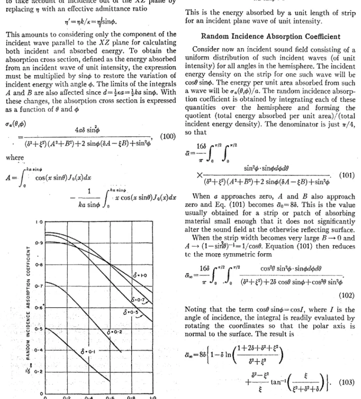
Figure I shows the variation of absorption coefscient with the parameter l / ( k a ) . The reciprocal parameter is chosen in order to show the transition to infinite area (l/ (ka) = 0). Particular values of l / ( k a ) , corre-
SUSCEPTANCE R A T I O , b
sponding to the standard sample size used in absorp-
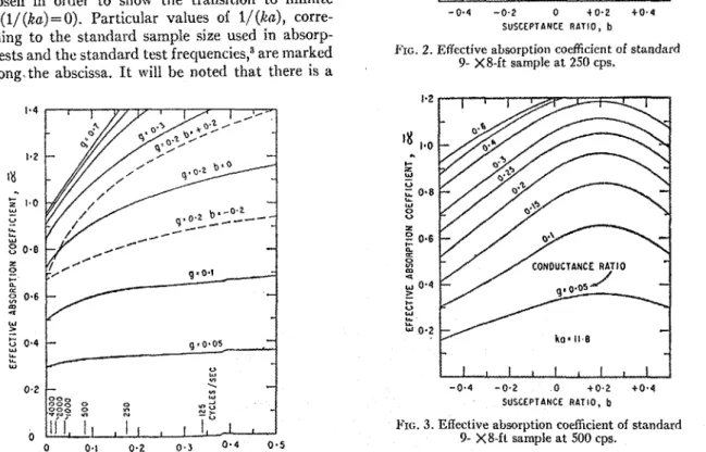
tion tests and the standard test frecjuenciesI3 are lnarked FIG. 2. Effective absorption coefficient of standard
9- X8-ft sample at 250 cps.
oif along\the abscissa. I t will be noted that there is a
-
ko= 11.0-
-
I I I , I , I , I - 0 . 4 -0.2 0 t O . 2 + O - 4 SUSCEPTANCE R A T I O , bFIG. 3. Effective absorption coefficient of standard
9- X8-ft sample at 500 cps.
rlc.
1. Eficliva a,,sorption as a farlction of sample dimensions Further information concerni~l~ the inlapinary corn- for a range of atIillittance ratios. Solid lines arc for real-admittance pollent is shown in Figs. 2-5, which include most of theratios (b=O); hroken lines show range of sdsceptance ratios for results for four of the stanclard test conditions. whereas
one value of conductancc ratio. for an infinite area (Fig. 6) the absorption is maximum
W. Kuhl, Acustica 10, 264 (1960). for zero susceptance, the peak shifts toward positive
"Tentative Method of Practice for Sound Absorption of
Acoustical Materials in Reverberation Roo@%" Am. Soc. Testing susceptance as the salnple size, relative to wavelength,