Publisher’s version / Version de l'éditeur:
Canadian Journal of Physics, 41, 1, pp. 167-177, 1963-02-01
READ THESE TERMS AND CONDITIONS CAREFULLY BEFORE USING THIS WEBSITE. https://nrc-publications.canada.ca/eng/copyright
Vous avez des questions? Nous pouvons vous aider. Pour communiquer directement avec un auteur, consultez la
première page de la revue dans laquelle son article a été publié afin de trouver ses coordonnées. Si vous n’arrivez pas à les repérer, communiquez avec nous à [email protected].
Questions? Contact the NRC Publications Archive team at
[email protected]. If you wish to email the authors directly, please see the first page of the publication for their contact information.
NRC Publications Archive
Archives des publications du CNRC
This publication could be one of several versions: author’s original, accepted manuscript or the publisher’s version. / La version de cette publication peut être l’une des suivantes : la version prépublication de l’auteur, la version acceptée du manuscrit ou la version de l’éditeur.
Access and use of this website and the material on it are subject to the Terms and Conditions set forth at
The creep of ice in bending
Krausz, A. S.
https://publications-cnrc.canada.ca/fra/droits
L’accès à ce site Web et l’utilisation de son contenu sont assujettis aux conditions présentées dans le site
LISEZ CES CONDITIONS ATTENTIVEMENT AVANT D’UTILISER CE SITE WEB.
NRC Publications Record / Notice d'Archives des publications de CNRC:
https://nrc-publications.canada.ca/eng/view/object/?id=5ed13e73-1bb7-46a8-9fe1-5e1d6909eb33 https://publications-cnrc.canada.ca/fra/voir/objet/?id=5ed13e73-1bb7-46a8-9fe1-5e1d6909eb33THE CREEP OF ICE IN BENDING'!' A. S. K~a~7sz-i-
iValiotza1 Researcl~ Cot~ncil, Ottawcr, Ca?zada
Received September 4 , 1962 ABSTRACT
Observations mere made on the creep behavior of colulnnar ice beams of tlilt'ere~it thiclinesses subjectecl to repeated ant1 revcrsed loading. More than half of the beams tested shoned trnlrsual creep behavior. During transient creep the strain rate increased to a maximum value arlcl clecreasetl only tliereaftcr. I t \\,as establishecl that this behavior was not a permanent property of ice. On reloatling, the same beanis eshibitetl ~iormal creep behavior. For the conditions of the esperi- ments, the deflection \\;as very sensitive t o the thickness of t h e beams. I t was founcl that the neutral axis was locntecl a t t h e center of the beam when t h e m a x i m ~ ~ m strain \\.as less than 1%.
Since the lniddle of the last century, various aspects of the creep behavior of ice have been studied and much information on this behavior is now avail- able. During the same period, the mathematical theory of nonelastic deforma- tions has been developed considerably and applied to creep problems. This theory has been used t o some extent t o describe the ~lonelastic deformation of ice (Meyerhof 1960) but advance in its application is hindered by the lack of relevant information.
The use of mathematics in the study of the creep behavior of ice can be enhanced in two ~ v a y s : by providing observations that call be used t o establish and check the theoretical equations, and by measuring those properties of ice that are required as basic data for calculations. I t was with these two objectives
in mind that a study on the creep of ice in bending was ~ ~ n d e r t a k e n . The observations were made on beams simply supported a t each end and loaded equally a t their one-third points. Both variable and constant bending moments could be studied s i m ~ i l t a n e o ~ ~ s l y with this symmetrical loading, the bending moment increasing linearly from the supports t o the loading points and being constant bet~veen them. T h e deflection was nleasured a t a number of locations along the longitudinal axis of the beam. From these measurements, the deflected shape of the beam was determined. i\4easurements were made from which the location of the neutral axis in the constant-bending-monlent section could be deter~nined. T h e effect of beam thickness on the deflection was studied in sollle detail.
In the course of the experiments an interesting phenomenon was observed: inore than half of the beanls showed an unusual creep behavior while the others behaved according to the conventional creep-time relationship. This was investigated to some extent and the results are included in this paper.
*Issued as N.R.C. No. 7117.
~ S I I O ~ . and Ice Sectiori, Division of Building Research, National Research Council, Ottawa. NOW a t University of Torollto for postgraduate studies.
Canadian Journal of Physics. Volume 41 (1963)
167
i ' , , \-I,
168 CANADIAN JOURNAL O F PHYSICS. VOL. 41. 1963
PREPARATION O F T I l E ICE BEAMS
A container, 24 in. in height and about the same in diameter, was filled with de-aerated tap water and cooled. Just before freezing, the water surface was seeded with snow. Ice plates grown by this method were about 4 in. thick, bubble free, and transparent, with long vertical grains about 1/8 to 1/4 in. in diameter. The crystalline structure of ice is hexagonal with a c/a ratio of
about 1.63. Because of conditions during growth, a preferred orientatioll developed such that the basal plane tended to be parallel to the long direction of the grains (Gold 1960).
The beains used in the study were 4 in. wide and of the thicltness show11 in Table I . They were cut on a band saw to almost their final dimensions and then
TABLE I
Dimension of beams used in the experiments Thiclaness, IVidt-h, Number of beams
Series No. ill. in. tested
machined accurately with a milling machine. They were cut so that the long axis of the grains was perpendicular t o the 4-in.-wide surface of the speci~nen. Ice covers of laltes and rivers are often coinposed of columnar grains with their long axis in the vertical direction. The orientation of the grains with respect to the applied bending stress was thus similar t o that occurring in many problems in the field involving the application of load t o ice covers.
During preliminary investigations, a few tests on beams of different thicli- nesses indicated that two beains could be considered geometrically identical only when they were machined to a tolerance of less than &0.5yo. Great care was talien to keep the t1~icl;ness of the specimens within this limit. I t was fouild that a variation in width of up to 2y0 had no observable influence on the deflection and so an accuracy of 1% was corlsidered satisfactory for this dimension.
E X P E R I M E N T A L M E T H O D
Four test series were carried out with beams of sizes a s given in Table I.
The apparatus used is shown in Fig. 1. The distance between the two supports was IS in. The loads were applied symmetrically, 3 in. on either side of the center line of the beain. T h e loading element and one of the supports were self- adjusting to prevent twisting and to distribute the load uniformly across the width of the specimen. T h e support could rotate freely about an axis parallel to the length of the beam and the loading element could rotate about two mutually perpendicular axes. Because of its flexibility the loading elenlent had to be guided and kept in place by a pair of vertical columns.
FIG. 1. 'The loading apparatus with beam in place. Kote the four metal strips frozen to the ice surlacc a t places of contact.
the deflection. The dial gauges were graduated i l l thousa~ndtl~s and had a range of 1 in. They ~Lre locatecl in the lo\ver part of the equipment not shown in the picture. The 11 rods under the specimen are the extensions of the dial gauges.
A time sequence camera was used t o record dial gauge readings for tests lasting one or more days.
Because the tests were made in a d r y , cold room and lasted sometimes for
24 hours or longer they were carried out in a plexiglass box containing enough crushed ice t o keep the air saturated and thus prevent evaporation of the specimen. T h e dimensions of several of the specimens were checked after test and no change could be detected when measured with an accuracy of in. A series of preliminary tests showed t h a t the supporting and loading elements penetrated the ice. As the beam deflected, there was a movement perpendicular to the line ot load and support. A scraping action resulted t h a t seriously affected the deflections. T o avoid this influence, narrow metal strips were frozen to the ice surface a t the places of contact with the apparatus (Fig. 1).
T h e maximum tensile and compressive strains were measured a t the constant- bending-moment section of the beam. Metal marlters were frozen oilto the surface and their distances measured with a traveling microscope before and after bending to an accuracy of a t least 0.3 X lop3 in. Since the maximum strain was about 1
%,
and the marlters were 4 in. apart, this corresponds to a n accuracy170 CANADI.4N JOURNAL O F PHYSICS. VOL. -11. 1063
of about 1%. The location of the neutral axis was calculated from the ratio of the mean maximurn tensile and compressive strain using the assulnption that the strain varied linearly with thickness.
T h e tests mere carried out with a constant load of 3 3 . 3 f 0.2 lb, producing a inaxiinun~ bending moment of about 25 in.-lb per inch in the constant bending moment section of the beam. The temperature was kept a t 14.5'f 0.S0F (-9.7"f 0.3' C). No effect of the temperature variation cou'ld be detected within the accuracy of the measurements.
RESULTS
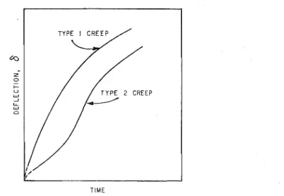
As the deflection-time relationslzip had the same character a t each measuring point, it was sufficieilt for inuch of the ailalysis to analyze only the deflection of the center. T h e creep rates and deflections presented in the figures are for the center. Thirty beams were tested, out of which about 10 showed the con- ventional creep curve (henceforth referred t o as Type 1 creep), while the other 20 beanls behaved unusually by having opposite curvature in the early part of the primary creep (Type 2 creep) as shown in Fig. 2.
a Z 5 I- " W 2 LL W 0 TIME
FIG. 2. Deflection curves typical of the t11.0 types of creep obscr~red.
This type of creep curve was rather unespected but by no means unheard of. Gold (1960) observed the saine behavior with polycrystalline columnar ice loaded in simple compression perpendicular to the long axis of the grains. The ice used for his experiments was prepared in the same way as for the present study. Griggs and Coles (1954) foulld similar creep curves for single ice crystals in compression. Some records mere found of similar observations on single crystal and multigrained specimens of other materials (Smith 1950; Penning and DeWind 1959).
A 12 to 15% scatter was observed in the deflections of the beains in each test series. Although this is not greater than the scatter observed in other studies of the creep of ice and other materials, the apparent consistency that was found
KRAUSZ: ICE CREEP I N BENDING 171
in t h e strain rate in secondary creep and the occurreilce of T y p e 1 a n d T y p e 2 creep suggested the expediency of ailalyzing the creep rates.
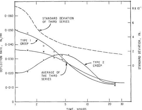
Observed creep rate - t i m e relationslzips for series 3 plotted in Fig. 3 show
clearly the difference between the two types of creep behavior. T y p e 1 creep starts with high stmin rate. This rate decreases gradually with time a s one
I
\ OF THIRD SERIES\
/
0
-
I I I I II 2 5 I 0 20 33
TIME, HOURS FIG. 3. Typical creep rate curves.
would expect for conventional creep behavior. For T y p e 2 creep, the initial creep rate is low. I t invariabl3. increases with time t o a maximum t h a t can exceed t h a t observed for T y p e 1 creep and decreases thereafter. \\7hilc the scatter in the initial creep rate of a lluillber of specimens tested under icleiltical conditions rnny be as much as 300"/0, after -1 to 5 hours the scatter was iound to have decreased t o about f 13%. UThen t h e secondary creep stage had been established, the scatter had decreased to a very sillall value.
T h e coilsistellcy in behavior TVCXS renzar1;able. Low ccrcep rate in t h e first I/:!
hour always iildicated the occurrence of T y p e 2 creep ivl~ile high initial creep rate was invariably followed by T y p e 1 creep.
T h e wide variatioil in initial deflections and creep rates indicates a differe~~ce in structure among t h e beams. Deformation appears t o reduce these differences, brillgillg about a more ullifor~n behavior, a s indicated by the decrease in the standard deviation. Once this uiliforillity is achieved, all beams might be expected to deform in a reasonably reproducible manner.
I72 C.-\S.\DIAK JOURNAL OF PIIYSICS. VOL. 41. 1963
curves presented to illustrate the observatiolls are typical for the temperature and load used.
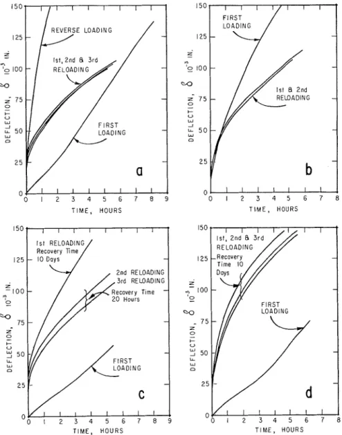
When the first loading time was less than 3 hours the first and second reloading curves were very different. A first loading time of at least 5 hours was necessary to reproduce the creep cilrves in repeated loading. An example is shown in Fig. 4 ( n ) . T h e reproducibility 011 reloading is quite significant considering that the beam was reloaded three times and the a c c u m ~ ~ l a t e d reloading time was lrlore than 15 hours.
0 1 2 3 4 5 6 7 8 5 T I M E , HOURS 1st RELOADING 125 - 10 Days - 2nd RELOADING 3rd RELOADING - 0 -0 1 2 3 4 5 6 7 8 T I M E , HOURS T I M E , HOURS T I M E , HOURS
FIG. 4. Typical loading cur\.es for beams from series 3. (Recovery times: (a) 20 hours between loadii~gs, and 10 days before reverse bending; (b) 20 hours between loadings; (c) 10 days before first reloading, 20 hours between first and second and second and third reloading;
KRAUSZ: I C E CREEP I K BENDING 173
A series of tests was carried out with first loadi~lg tirnes between 8$ and 52 hours. I t was observed in these tests t h a t repeated loading always produced about the same creep curve even when the first loading curves were quite different (Types 1 and 2 ; see Figs. 4(a) and 4(b)).
T h e effect of the recovery time on subsequelit creep was investigated extensively. When the time of recovery was 10 days the beams were 30 t o 40% softer than when it mas 20 hours. An exa~ilple from series 3 is shown in Fig. 4(c). If tlie recovery time mas also 10 days, beams subjected to tlie same load had about tlie same reloading curves fairly consistently (e.g., Figs. 4(c) and (d)).
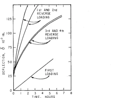
Some beanis were reloaded in the opposite direction. Examples of the observed deflections are s11ow11 in Figs. 4(a) and 5. T h e creep in reversed bending is of Type 1. Beams that exhibited Type 3, creep initially have lost this
behavior completely. T h e two beams shown have allnost identical first r-everse- loading curves, although their recovery times were 20 days and 10 days re- spectively. This suggests t h a t the effect of recovery time decreases considerably after 8 to 10 days. Further bending in tlie same direction showed somewhat inconsistent results, but there does appear t o be a tenclency for the creep curves on repeated loading t o become about the same as beiore the reverse loading
(compare Fig. 5 with 4(a) and 4(d)).
0 1 2 3 4 5 6 7 8
T I M E , HOURS
FIG. 5. Loading and reverse loading curves of beam from series 3. (Recovery times: 20 days bcfore lirst reverse loading and 6 days bcfore second rcverse loacling; 30 hours before third reverse loading and 3 clays before fourth revcrse loading.)
Some of tlie structural changes that occur during bending and recovery were studied by etching tlie ice surface and observing grain-boundary migration and s~~bbounclary formation (Icrausz 1961). Grain-boundary migration was ob- served within
i
hour after the load was applied. Some boundaries became very jagged and migrated relatively fast during the first 5 to 8 hours. After 5 t o 8174 CANADIAN JOURNAL O F PHYSICS. VOL. 41. 1963
hours, the migration slowed down considerably. As a n extreme case of grain- boundary migration, the complete disappearance of a grain was sometimes observed. Subboundaries develop during t h e first few hours of creep: their location and number d o not appear t o change appreciably afterwards. They are remarltably straight and parallel in contrast to t h e large-angle boundaries. Grain-boundary migration was also observed during recovery. T h e jagged large-angle boundaries migrated so t h a t their length decreased, thus acquiring a more stable thermody~lamic state.
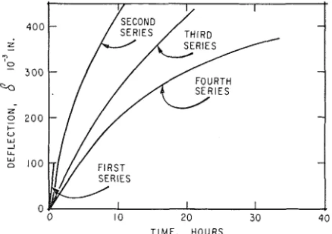
T h e dejection - beam thickness relationship was investigated for the four series of tests. (Beam sizes are given in Table I.) T h e average creep curve for each of the series begins with a linear primary creep, and after a deflection of approxi- mately 150X10-3 in., t h e rate of creep gradually decreases (Fig. 6).
T I M E , H O U R S
FIG. 6. Tlie average initial creep curves for the four series.
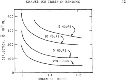
T h e relation between average deflection a t a given time for each series and the beam thicl;~less is sho\v~l in Fig. 7. Beams 0.0 i l l , thick failed in less than
$ haul- and were omitted f r o ~ n the figure. 111 the cases when failure occurred the ice brolte sudde~lly. No cracks were detected prior t o failure nor mere tlley observecl t o for111 in the other beams during bending.
For the size of bea~ils used in the esperiments, the clellectio~l is grcatly affected by the thickness. After 2$ hours of creep the 1.000-in.-thick beam had about 100yo greater deflection than the 1.033-in. beam. Even after 15 hours of creep, 151; differellce in thicltiles~ in beams less than 1.25 in. thick will have a n appreciable effect on the deflection.
T h e avrrage dcJected shal~e of the beams in the variable-be~icli~lg-~~lo~nent section was parabolic for the second series b ~ ~ t deviated from parabolic in the third and fourth series. T h e equation for the average shape in this section, after five hours of deformation, was found t o be
KRAUSZ: I C E CREEP I N BENDING
15 HOURS
5 HOURS
THICKNESS, INCHES
FIG. 7. The average relation betxveen thickness and deflection a t different times.
(b) for the third series of tests:
( 1 ) 6 = 2.7X l o p 3 [($1)1.9-X1.9 ] i n . ;
(c) for the fourth series of tests:
I-Iere 1 is the length of the bearn and X is the dista~lce from the middle of the beam measured in inches.
I n the constant-bending-1no111ent section, the beam was expected t o bend into t h e arc of a circle. Although individual beams may deviate as much as
20 t o 26y0 from the circular shape, the average deflection curve was circular to witllin 2%.
T h e location oJ the ~zez~tral axis was determined by the method already des- cribed. Observations showed t h a t t h e maximum strain in tension a n d com- pression \vas about the same and so i t was considered t h a t the neutral axis mas located approximately a t the center of t h e cross section. T h e calculated position of the neutral axis was always within f 0.03 in. of the center of the beam.
CONCLUDING IIEi?IARI<S A N D SUMiLIHIIY
T h e purpose of the experiments was t o provide further information on the creep of ice required for stress analysis. During preliminary tests an u~lusual creep behavior ~ v a s observed and mas investigated t o some extent.
T h e tests were made on beams 4 in. wide, 18 in. long, and 0.9 to 1.2 in. thick. T h e beams were s i ~ n p l y supported and subjected to a load of lG.G.5 Ib a t their one-third points.
T h e following observations were made and conclusions drawn:
1. Fewer than half of the 30 specimens deformed according to t h e conven- tional creep-time relationship. T h e others showed accelerating creep in the
176 CANADIAN JOURNAL O F PHYSICS. VOL. 41, 1063
early stage of primary creep. For these specimens, the creep rate attained a maxin~um value and then decreased t o about the same minimum creep rate as observed for specimens t h a t deformed in the conventional way. Scatter in the initial creep rates of beams subjected t o the same load was as much a s 300%. This scatter decreased with time t o a negligible value in the secondary creep stage.
2. Un~isual creep behavior is not a permanent property of ice. F o r the con- ditions used in the experiments, this cl~aracteristic is lost after 8 to 10 hours of creep. When reloaded, i~lcluding reverse bending, all beams sho~ved the con- ventional creep behavior.
3. Deflection up011 reloading was dependent on t h e recovery time betlveen loaclings. Once the unusual creep behavior was lost, the creep of equivalent beams subjected to the same load conditions and recovery time was similar and reproducible.
4. Structural changes, such as grain-boundary migration and subboundary formation, were observed during the first 8 t o 10 hours of creep. These structural changes appear to slow down .ivith time and almost no c h a ~ i g e was observed after 10 hours.
5 . During recovery considerable shortening of distortecl grain boundaries was observed. These migrations hacl almost ceased by 10 hours after the removal of the load.
6. T h e observations suggest t h a t deformation causes all the beams to acquire the same structul-e. Once this structure is obtained, t h e deformation becomes similar and reproducible.
7. Under the conditions of the experiment i t was observed that t h e average of the deflection curves for first loading for each series of experiments has a linear part in the early primary creep stage.
8. I f the beam is less than 1.25 in. thick, the deflection for the s a m e load is very sensitive to the thickness of the beam. Specimens must be machi~led to a n accuracy of a t least 0.;3Y0 to obtain consistent results.
9. Beams 0.900 in. thick failed under t h e applied load within 1/2 hour urhile those 1.000 in. thick supported the same load for '7 hours without developing a n y cracks or showing a n y sign of tertiary creep.
10. T h e beams are bent into the arc of a circle in the constant-bending- moment section. T h e shape of the beam in the variable-bendiilg-11101let section was parabolic in series 2 but cleviated from parabolic for series 3 ancl 4.
11. I n none of the tests did the maximum strain exceed 17,. I t was approxi- mately the same in compression as in tension, indicating t h a t the neutral plane remained a t the center of the beam.
I t is the pleasure of the author t o acknowledge the assistance given b y Mr.
J . Booth in conducting the experiments. This is a contributio~x from the Division of Building Research, National Research Council, and is published with the approval of the Director of the Division.
KRAUSZ: ICE CREEP I N BENDING 177 REFERENCES
GOLD, L. W. 1960. Can. J. Phys. 38, 1137.
GRIGGS, D. T. and COLES, N. E. 1954. Creep of single crystals of ice. U.S. Corps of Engi- neers, Snow, Ice and Permafrost Research Establishment, Report KO. 11.
I<~ar;sz, A. S. 1961. J. Glaciol. 3, 1003.
MEYERHOF, G. G. 1960. Proc. Am. Soc. Civil Engrs. 86, E M No. 5 , 113. PENNING, P. and DEWIND, G. 1959. Physica, 25, 765.