PFC/RR-82-35
DOE/ET-51013-66
I UC-20
Design Features of T-2,
A Torsatron Reactor with
Continuous, Demountable Coils
R.E. Potok, D.R. Cohn, L.M. Lidsky
Plasma Fusion Center
Massachusetts Institute of Technology
Cambridge, MA 02139
Design Features of T-2,
a Torsatron Reactor with
Continuous, Demountable Coils
R.E. Potok, D.R. Cohn, L.M. Lidsky
Abstract
This report describes the features of the continuous-winding torsatron reactor T-2, and presents numerical computations of the reactor's ion thermal conductivity. The helical magnet system is comprised of modular units, with the coils connected through demountable, resistive joints at the module interfaces. Reactor maintenance can be performed through the access existing between the helical coils (without moving the coils). This design feature combines desirable features of both the continuous and modular coil concepts; the continuous current paths provide more vacuum rotational transform (i) and reduce the out-of-plane forces on the coils, while the demountable joints allow for magnet maintenance and replacement. The blanket modules would be be of moderate size (the blanket structure of the illustrative reactor design was divided into three sections for each of the
19 field periods, the sections weighing 500, 100, and 25 tonnes). Our results indicate that the coil
winding law can be optimized to produce adequate access and good flux surface quality. Because of the high values of ion conductivity, it may not be possible to obtain sufficiently large values of nr for ignition unless the coil minor radius and aspect ratio are large. The presence of large ambipolar electric fields, however, could reduce the ion conductivity to values which would allow for reactor designs with major radii of 20 to 30 meters and thermal power levels less than 4000 MW.
Table of Contents
AbstractTable of Contents
Chapter I - Introduction and Summary
1.1 Overview of Current Design App
1.2 T-2 Design Approach
1.3 Joint Design and Choice of I Nur
1.4 Thermal Transport and Ignition
Chapter
II
-2.1
2.2
2.3
Magnetic Surface Analysis
Optimization Parameters Analysis of an i = 3 Configuration Analysis of an t = 2 Configuration
1
2
4 4 5 79
1313
13
15
Chapter III - Ion Transport Analysis 32
3.1 Description of Numerical Procedures 32
3.2 Scaling of Ion Transport 33
Chapter IV - Illustrative Design 39
4.1 Analysis of Resistive Joints 39
4.2 Representative Assembly Procedures 42
Chapter V - Conclusions and Future Directions 62
Acknowledgments 66
References 67
Chapter I: Introduction and Summary
Section 1.1
-
Overview of Current Design Approaches
There are a number of advantageous design features inherent in the torsatron reactor concept, among them being 1) steady-state, disruption free operation, 2) a built-in magnetic divertor, 3) low recirculating power, and 4) plasma start-up on existing magnetic surfaces. Within the torsatron concept, there are two primary design approaches, continuous",23) and modularM) helical coil sys-tems. The trade-offs between the two approaches involve the support structure for the coils and the assembly and maintenance procedures for the reactor, which will now be discussed.
The modular coil systems offer a comparatively easy assembly and maintenance procedure; each coil module and its associated blanket can be removed from the outboard side of the torus and be serviced away from the nuclear island. The principle engineering disadvantage of the modular system is the large forces and torques the modular coils exert on each other. The out-of-plane forces of a modular coil set are approximately twice that of a continuous winding(5), and it remains to be seen whether these loads can be acceptably supported. It is also more difficult to produce a high rotational transform (I) with the modular coil design, resulting in a lower critical , and lower plasma performance.
Several continuously wound torsatron reactor studies have been done at Kyoto University(67' ), at MIT(',2), and at the Karkov Institute of the USSR(*8>). Except for the MIT design, the continuous
winding approach is based upon helical coils that are 100% reliable and last for the life of the plant. Blanket maintenance would be done through the access existing between the helical windings. Since
there is at present no expertise in operating superconducting magnets in a nuclear island environ-ment, the requirement of continuous torsatrons for life-of-plant (LOP) coils makes this concept less attractive than the modular approach.
The MIT T-1 design(') attempted to eliminate the worst features of both the continuous and modular coil configurations. The T-1 design was based upon continuous, superconducting, helical coils. The reactor was divided into 20 modular units consisting of blanket, shield, magnet segments, and support structure. Resistive joints were used to connect the superconducting helices at the module interfaces.00) Normal blanket maintenance required unclamping the resistive joints, lifting the module up, and then removing the module from the nuclear island.
The principle objection to the T-1 design concerned the reliability of the resistive joints. The actual power consumption of the joints was low (2 to 5 MW of room temperature electric power), but the frequent clamping and unclamping of the numerous resistive joints for blanket maintenance (4,380 individual conductor-plate joints comprising 60 resistive breaks in the helical coils) was considered to be a very time consuming operation, resulting in poor plant availability.
Section 1.2
-
T-2 Design Approach
The new design feature presented in the report greatly reduces the disadvantageous aspects of the resistive joint design, while still keeping its advantages over the pure modular or continuous designs. In the new design, resistive joints are used to connect the superconducting helical segments, but these joints are clamped once during construction, and are only unclamped if a magnet failure occurs. Blanket and shield maintenance will be done through the access existing between the helical
maintenance is necessitated by neutron activation. In the event of a magnet failure, considerable time (on the order of several months to a year) might be required to replace a superconducting segment, but this should have only a small impact on the expected plant availability, given the high reliability of superconducting magnets. Due to the large coil aspect ratio of torsatrons (the T-1 design had an aspect ratio of 7.3 , and an on-axis field of 5 tesla resulted in a peak field at the coils of only 8.7 tesla), niobium titanium (NbTi) superconductor can be used for the helical coils. The use of ductile superconductor would ease the fabrication procedures for bending the coil segments into the desired helical shape. For a typical
e
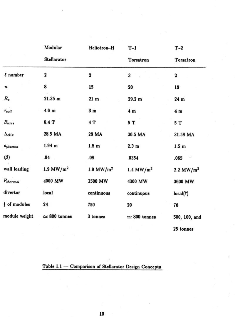
= 2 reactor design, with a major radius R, of 24 meters and 19 field periods, the average coil segment would be approximately I winding period in length c 25 meters).An illustrative design (referred to as the T-2 design) has been developed using the above men-tioned assembly approach. Table 1.1 presents a comparison of the T-2 torsatron design with the
LASL modular stellarator design(4), the Heliotron-H design of Kyoto University(3), and the MIT
T-1 design(O. A key advantage of the T-2 design is the small size of its blanket modules, compared
to the modular stellarator and T-1 designs. The Heliotron-H design relies on very small blanket modules which are stacked vertically upon one another during assembly. It might be very difficult to get a reliable vacuum seal at the surface of these three tonne modules, and the Heliotron-H reactor would probably have to enclosed in a large vacuum chamber. It is at present unclear where the optimum vacuum surface would be for the other reactor designs, though both the LASL and MIT designs assumed a vacuum seal at the first wall with the coils and support structure external to the vacuum chamber. A perspective view of the T-2 reactor is shown in Figure 11 .
Section 1.3 - Joint Design and Choice of J Number
The helical magnet system is comprised of modular units, with the coils connected through resistive joints at the module interfaces. These joints will be connected once during plant construc-tion, and will only be disconnected if magnet failure occurs. Reactor maintenance will normally be done through the access existing between the helical coils. This design feature combines desirable features of both the continuous and modular coil concepts; the continuous current paths provide more vacuum rotational transform (E) and reduce the out-of-plane forces on the coils, while the
resistive joints allow for magnet maintenance and replacement. The blanket modules would be be of moderate size (25 to 500 tonnes each).
The winding law and equilibrium coils should be optimized to produce: 1) good blanket access, 2) sufficient well, rotational transform, and shear, and 3) helical and toroidal ripple configurations that result in acceptably low ion heat transport. The choice of t number and winding law controls the access available for blanket module insertion. For an t = 3 configuration, the separatrix
sur-face is approximately circular and nested well within the helical coil minor radius. The optimum module design would probably involve utilizing the outboard access by inserting the blanket modules horizontally from the outboard side and then translating them toroidally into position. There would be approximately 4 or 5 blanket modules per field period, weighing = 150 tonnes each.
For an t = 2 coil configuration, the plasma has an elliptical cross-section, with the maximum separatrix radius equal to the helical coil radius. In this situation, the blanket modules would also be elliptical in cross-section, and there would not be sufficient space to translate the modules toroidally underneath the helical coils. Due to the greater access available with an t = 2 system, it would
be possible to utilize the helical access by inserting the modules directly into position from the top, outboard, and inboard positions of the reactor (three blanket modules per field period). A large blanket section weighing c 500 tonnes would be inserted from the top, a 100 tonne section inserted from the outboard side, and a 25 tonne section inserted from the inboard side. Most of the blanket structure is accessed from the top in order to minimize the torque moments associated with the movement of the side sections.
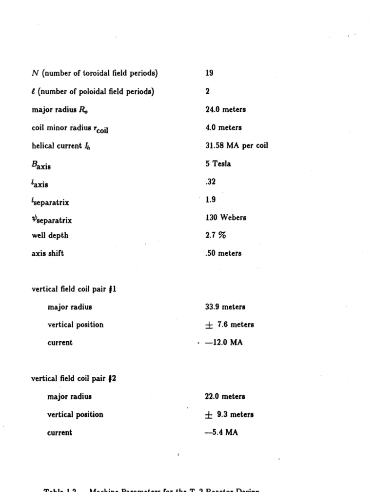
A cross-section view of the nuclear island is shown in Figure 1.1, and illustrative values for
the machine parameters are given in Table 1.2 .Due to easier assembly procedures, an t = 2 coil configuration was found to be superior to an t = 3 configuration. The I = 2 system offers more access to the blanket modules, which can be inserted directly into position from the top and outboard sides of the reactor (two blanket modules per field period). In contrast, the blanket modules of an
t = 3 system are inserted from the outboard side, and then translated toroidally into position (four
or five blanket modules per field period). The
e
= 2 configuration also produces more shear and rotational transform within the vacuum magnetic well, and henice offers the potential for improved plasma # limits and ion energy confinement.A key feature of the T-2 reactor concept is the design of the resistive joints connecting the
helical, superconducting segments. These joints will only be broken for magnet replacement, since the blanket modules are removed through the access between the coils. Under these conditions, it is preferable to solder the resistive joints, rather than connect them through pressure contacts. The pressurized joints offer a faster disassembly, since it is not necessary to warm the entire magnet system before breaking a joint. However, these joints require a fine tolerance across the conductor
plate contact surfaces, and it is questionable whether the necessary tolerances could be maintained in a reactor environment.
The soldered joints would eliminate the need for the joint pressure-clamps and for the fine machining of the conductor plate contact surfaces. In order to break the soldered joint, the solder would first be melted and pumped away. The room temperature refrigeration power requirement for all the resistive joints in the illustrated power reactor is on the order of 1 MW.
Section 1.4
-
Thermal Transport and Ignition
Our numerical calculations of the ion conductivity show "plateau scaling" proportional to ehet Ti/t
(where eh is the helical ripple, ei is the toroidal ripple, Ti the ion temperature, and i the rotational transform). This scaling is consistent with a transport model in which the diffusion is dominated by particles trapped in the helical ripples and making large excursions from their initial flux surfaces. Our results indicate that, because of the high values of ion conductivity associated with these ripple losses, it may not be possible to obtain sufficiently large values of nr for ignition unless the coil minor radius and aspect ratio are large. This combination leads to a large major radius and very large total thermal powers (on the order of 10,000 MW) for typical wall loading (2 MW/M2). However, the
presence of large ambipolar electric fields could reduce the ion conductivity to values which would
allow for reactor designs with major radii of 20 to 30 meters and thermal power levels less than 4000
MW. A self consistent analysis of the formation of this electric field, and its effect upon impurity
build-up, should be the next step in the development of the torsatron reactor concept.
Modular
Stellarator
Heliotron-H
T-1
Torsatron
T-2
Torsatron
t number
n
R. Bazi, 'helix aplama(0)
wall loading
Ptherma.divertor
J of modules
module weight
2
8
21.35 m
4.6 m
6.4 T
28.5 MA
1.94 m
.04
1.9 MW/M 24000 MW
local
24
~ 800 tonnes
2
15
21 m
3 m
4 T
28 MA
1.8 m
.08
1.9 MW/M23500 MW
continuous
750
3 tonnes
3
20
29.2 m
4 m
5 T
36.5 MA
2.3 m
.0354
1.4 MW/M
24300 MW
continuous
20
~ 800 tonnes
2
19
24 M
4 m
5 T
31.58 MA
1.5 m
.065
2.2
MW/M23600 MW
local(?)
76
500, 100, and
25 tonnes
-41b VV --4y . -1 4
o
. lk' --N (number of toroidal field periods) i (number of poloidal field periods)
major radius R,. coil minor radius rcoil helical current Ih Baxis !axis Iseparatrix t 'separatrix well depth axis shift
vertical field coil pair 11 major radius
vertical position current
vertical field coil pair #2 major radius vertical position current 19
2
24.0 meters 4.0 meters 31.58 MA per coil 5 Tesla.32
1.9
130 Webers 2.7% .50 meters 33.9 meters±
7.6 meters - -12.0 MA 22.0 meters±
9.3 meters-5.4 MA
the flux surfaces. The shape factor S was varied from I to 1.5 (from constant pitch to approximately the ultimate configuration). It was found that the access constraint could be satisfied for a large range of winding parameters, while still retaining good surface quality. (Typical parameters might be: S = 1.2, A1 = 0, A3 = -. 04.) From a series of particle orbits tracked in vacuum fields, it
appears that the increased access does not result in large distortions of the particle orbits, but the effects of these winding modulations on particle transport are still unexplored.
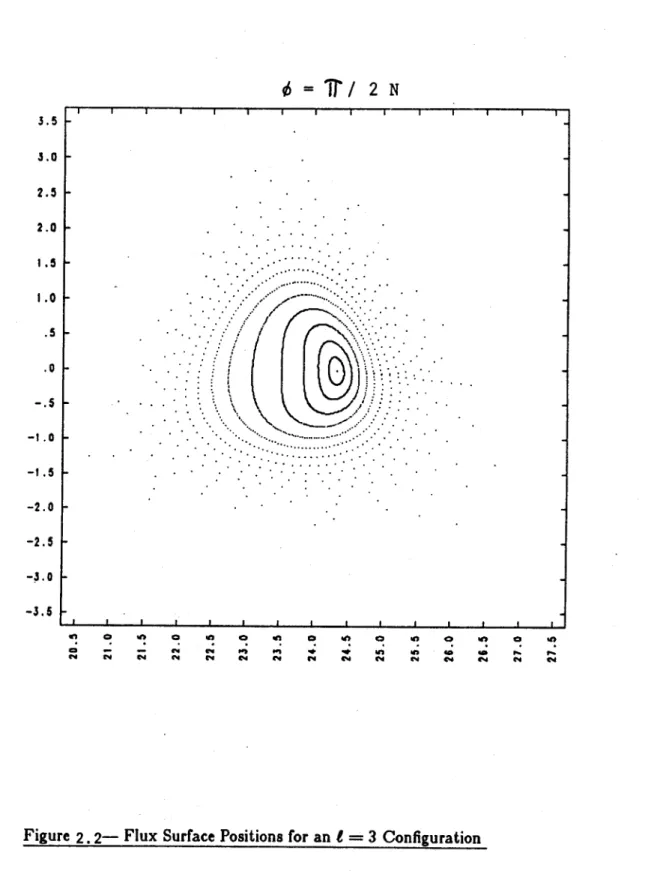
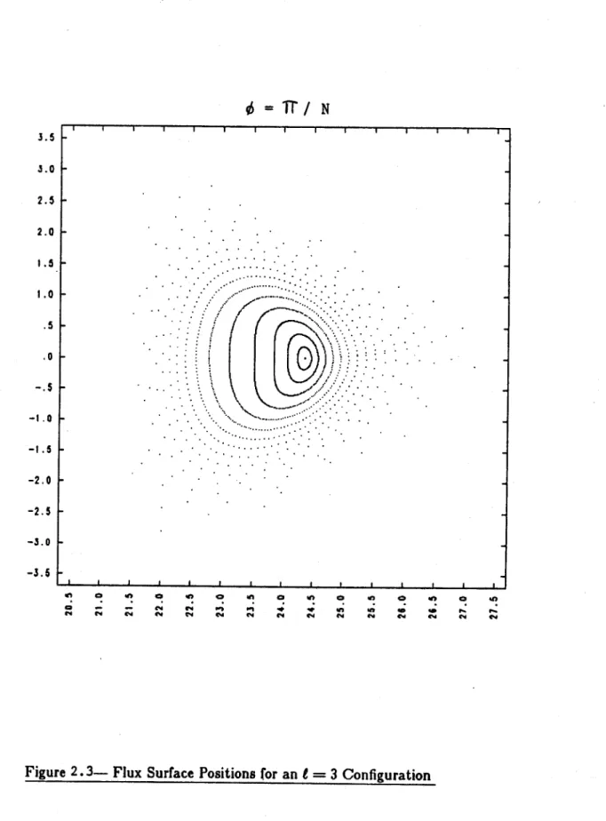
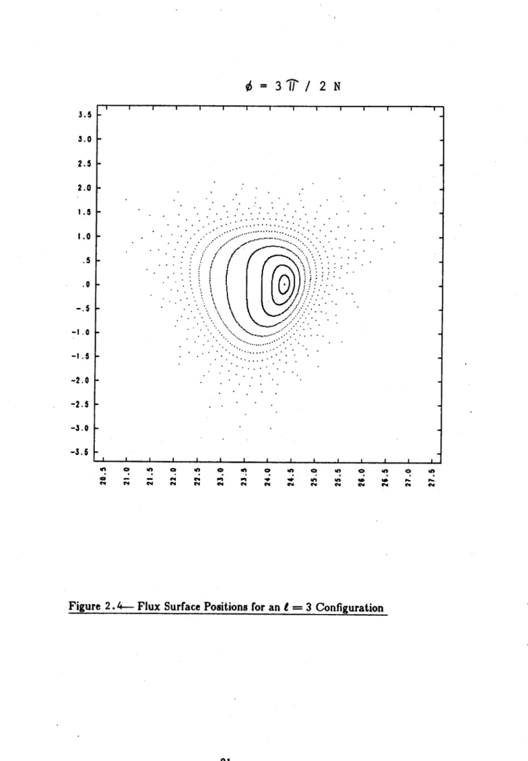
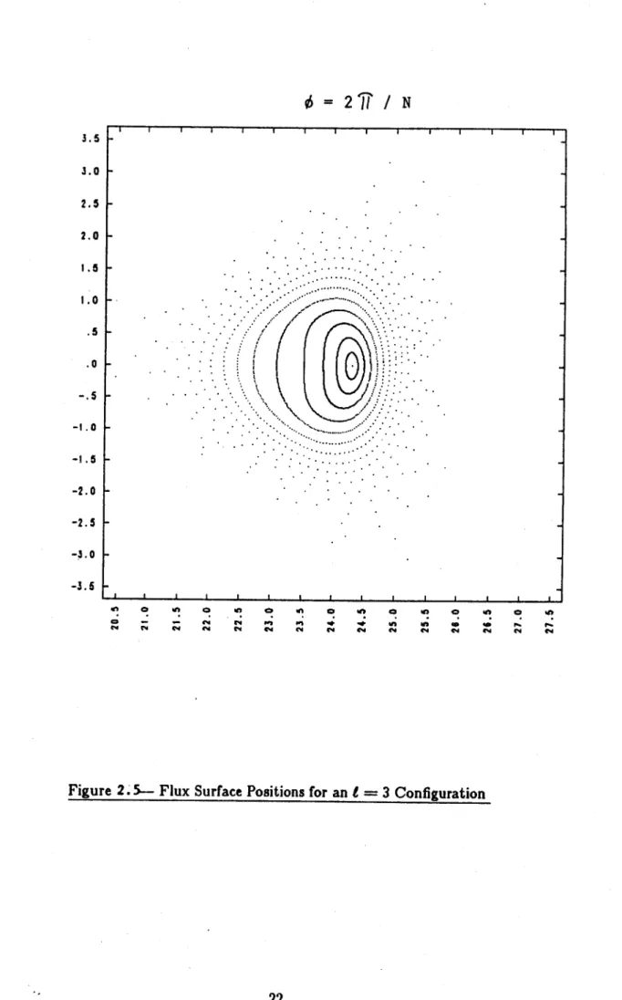
The machine parameters of a representative t = 3 reactor are given in Table 2.1 . The flux surface positions at various toroidal angles (from 0 = 0 to lphi = 27r/N) are shown in Figures 2.2 to
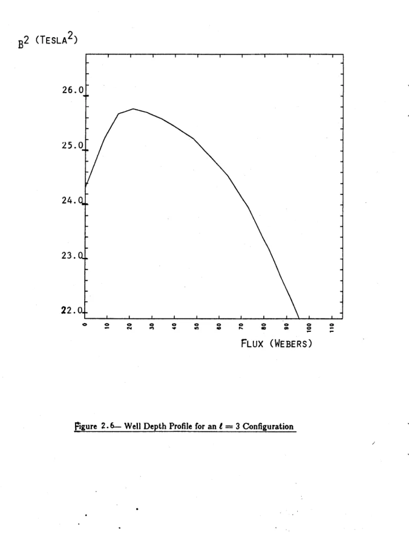
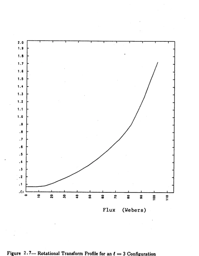
2.5 . The magnetic well profile ((B2) versus flux) is shown in Figure 2.6, and the rotational transform
profile (I versus flux) is shown in Figure 2.7 . The surface positions near the separatrix should be considered approximate, since the winding law and vertical field coils have not be optimized with respect to the access and divertor requirements.
Section 2.3
-
Analysis of an
=2 Configuration
The t = 2 reactor would have a different assembly procedure and access requirement. Due to the presence of only two helical coils, the access between the coils is greatly increased. Because of the elliptical shape of the plasma (which rotates in
#),
the outboard access approach of the I = 3systems can not be used unless the blanket modules are screwed toroidally into position (as opposed to a simple toroidal translation), or unless a mechanical limiter is used to restrict the plasma minor radius. Otherwise, the plasma radius between the coils is approximately equal to the coil radius,
and there is no room for the blanket module to pass underneath the helical coils as it is translated toroidally.
Due to the great increase in access available with the i = 2 system, it is preferable to insert the blanket modules from the top, outboard, and inboard sides of the reactor. The blanket modules would be elliptically shaped to match the local plasma contours, and no further movement of the modules would be required once they are inserted into place. The access ports must of course be compatible with the space requirements of the helical coil structural support system. Support structure enclosing the blanket access ports might have to be removed before blanket maintenance could begin. Analytical calculations(") show that the support structure of a torsatron reactor would be of reasonable thickness, though a comprehensive analysis of the support, access, and divertor requirements has yet to be done.
The machine parameters of a representative 1 = 2 reactor are given in Table 2.2 . The flux surface positions at various toroidal angles (from 4 = 0 to 4 = 2r/N) are shown in Figures 2.8
to 2.11 . The magnetic well profile ((B2) versus flux) is shown in Figure 2.12, and the rotational
transform profile (I versus flux) is shown in Figure 2.13 .As with the i = 3 surface plots, the surface
positions near the separatrix should be considered approximate, since the winding law and vertical field coils have not be optimized with respect to the access and divertor requirements. The inner set of vertical field coils in Table 2.2 (with a major radius R? = 22.0 meters) would probably be
re-positioned with a major radius of about 19 meters in order to provide overhead access to the blanket modules.
S
=
1,466
S
=
1.233
S
=1
S
=.8597
N
I
shape parameter S
major radius R.
coil minor radius rcoil
helical current
IhBaxis
Laxis
Iseparatrix
'Pseparatrix
well depth
axis shift
vertical field coil pair 11
major radius
vertical position
current
vertical field coil pair $2
major radius
vertical position
current
19
3
1.00
24.0 meters
4.0 meters
31.58 MA per coil
5 Tesla
.067
1.8
110 Webers
5.6%
.30 meters
33.8 meters
±
8.0 meters
-20.6 MA
22.0 meters
±
8.2 meters
-6.6 MA
d= 7/
2 N
3.5 3.0 2.5 2.0 I1 .0 1.0 --- - ---- -.5 ---. 5 -1.5 -. . - . .. -2.0 -2.5 -3.03.5 '4! C.4 0 (.4 C! 0 '.4 In 4 C.' ,nc.' '42 C!' (.4 (.4 'a I.-C.'
Figure 2.3- Flux Surface Positions for an t = 3 Configuration
=T/
N
I I I I t I I-K
-
-
.H
2.5 2.0 1.5 1.0 .5 0 -I CI
-2.0 -2.5 -3.0 -3.5 W! '.4 a '.4 In C.' a '.m C40
= 317 /
2 N
3.5 3.0 2.5 2.0 1.5 1.0 -.5 -l.a -1.5 -2.0 -2.5 | -3.6 en a e A e C cm en e C! to cmd enFigure 2.4- Flux Surface Positions for an I = 3 Configuration
I I I t I I I I
-CI p..en .5
=
2I / N
.5 k-3.5 3.0 2.5 2.0 I.5 l.0 .5 .0 C. a 1~4 Ca cm4 cm4 4! '.4 ('I a -I 4.4 Ca '.4 (.4 ,nc., An(.4 a C.4Figure 2.5- Flux Surface Positions for an t = 3 Configuration
.
...
--t .0 -2.0 -2.5 -3.5 'S (.4B
2(TESLA
2)
I I I I I I I26.0
25.0
24.0
23.Q
22.0..
FLUX (WEBERS)
2.0 1.9 1.5 1.7 1.6 1.5 1.4 1.2 1.1-1.0 .9 .7 .6 .4 .0
.2-Flux
(Webers)
N
19
2
shape parameter Smajor radius R, coil minor radius rcoil helical current I Baxis !axis Iseparatrix Oseparatrix well depth axis shift
vertical field coil pair fI major radius vertical position current
vertical field coil pair 12 major radius vertical position current
1.00
24.0 meters 4.0 meters 31.58 MA per coil 5 Tesla.32
1.9
130 Webers 2.7% .50 meters 33.9 meters±
7.6 meters-12.0 MA
22.0 meters±
9.3 meters-5.4 MA
S='
it/
2 N
4.5 4.0 3.5 3.0 2.5 2.0 1.5 1.0 .5 .0 -. 5 -1.0 -l. -2.0 -2.5 -3.5 -4.0 -4.5 m -~ ~
~
~
t mI n q w~ co q t- 44 C4. cm 94 C4 C % C 4 m C4 C4.5 4.0 3.5 3.0 2.5 2.0' I.5 1.0 .5 .0 -. 5 -1.0 -I . -2.0 -2.5 -3.0 -3.5 -4.0 -4.5 c" C 4 C 8 C . C cm -4 CO C4
Figure 2.9- Flux Surface Positions for an t = 2 Configuration
T
/ N
I I I I I I I I I I I I I I I I I -~~
. . . --*0 1 .0 a. Pd4.5 4.0 3.5 3.0 2.5 2.0 1.5 1.0 .5 .0 -. 5 -1 .0 -1 .5 -2.0 -2.5 -3.0 -3.5 -4.0 -4.5 =
2W/
3 N
-I
I
I-C U' C! .n 0i n C C I C! W! In C . C!0C : 94 " m m~ -W .* Il Il l B 1 44 cm N4 CI 94 Nl CN C4 N4 N4 Nft
6 = 271 / N 4.5 4.0 3.5 3.0 2.5 2.0 '.5 1.0 .5 .0 -.5 -t.0 -1 .5 -2.0 -2.5 -3.0 -3.5 -4.0 -4.5 4 ! C W! C! i A4 ;z ;4 1 4 4 C4 o I C I C I to a 0 I e C-4 1. 14 C4 1.4 C4 1.4 :1. 14 1' 14
Figure 2.11- Flux Surface Positions for an I = 2 Configuration
I I I I I I I
In
C7
0-B
2(TESLA
2)
25.0.
24.0-
23.0-22. 0.
I I I I I I I I I I C3 0 C2 a a to -0 40*P' 0 0 - 0FLUX (WEBERS)
2.0 1.9 1.8 1.7 1.6 1.5 1.4 1.3 1.2 1.1 - -1.0 -- .8-.7 -- .6-.5 .3 --.2
.1-Flux
(Webers)
Chapter III: Ion Transport Analysis
Section 3.1
-
Description of Numerical Procedures
A key question in the development of the stellarator reactor concept is the scaling of ion transport
in the reactor regime. Early, pessimistic estimates based on transport in rippled tokamaks have been found to be invalid('2,3), but the requirement for a sufficiently low ion conductivity (needed
for ignition) still critically controls reactor size and overall reactor desirability.
The diffusive ion heat transport in a stellarator is dominated by the particles trapped in the helical and toroidal ripples that exist on the flux surfaces. A particle trapped in these ripples can exchange angular momentum with the magnetic field, and make a large excursion from the initial flux surface. The particle will be lost if its drift orbit crosses the separatrix.
In this study we have made numerous numerical calculations of ion conductivity (xi) in the stellarator reactor regime. The conductivity was measured by launching test particle distributions within a given region of flux, tracking the test particle orbits (with background collisional effects included), and measuring the growth rate of the flux width of the test distribution(12). The test ions were launched with an isotropic, Maxwellian distribution, and interacted with the background plasma through classical electron drag, ion drag, ion pitch angle scattering, and ion energy scattering. Background temperature and density were assumed to be independent of the flux position, and a typical simulation involved tracking approximately 2000 particles for 5 to 20 poloidal orbits each. Several particles might leave the machine on a given run due to their uncompensated drift, and when this occurred, the calculated ion conductivity was increased so that the conductivities reported here
represent an effctive diffusion rate which would match the net heat transport measured. Except for the lost particles, the particles' flux coordinates were recorded only when the particles crossed the horizontal mid-plane on the outboard side of the magnetic axis. In this manner, the periodic, non-diffusive motion of the particles away from the launching region (due to the vacuum orbit motion) was eliminated from the growth rate of the distribution.
Section 3.2
-
Scaling of Ion Transport
Tables 3.1 and 3.2 present the parameters of eight reactor configurations that were studied. The data show the scaling of Xi with respect to aspect ratio, minor radius, I number, and outward shift of the magnetic axis from the geometric minor axis. The test and background particles had a mass of 2.5 u, with a density n, = ni = 2.5 X 10²⁰/m3, and a temperature T = T, = 10 keV. The
toroidal magnetic field on axis was 5 tesla. For the I = 3 systems, coil aspect ratios of 4 to 10 were
studied, with coil radii of 4 meters. The outward shift of the magnetic axis was necessary for the formation of a vacuum magnetic well. Reactors J1 through #7 had a peak vacuum well of 2.5% to
6.0%, while reactor $8 had no magnetic well.
The data in Tables 3.1 and 3.2 show that a significant improvement in Xi occurs with coil aspect ratios of 6 to 10, compared to a coil aspect ratio of 4. The data can also be fitted to an empirical scaling law. For the cases with a magnetic well, Xi was found to be proportional to ehet/Ir,2,. The increased helical ripple th of the I = 2 systems is partially offset by the increased rotational transform
aspect ratio and N number, I = 3 systems have much less helical ripple than the t = 2 systems, due to the increased perpendicular distance between the I = 2 coils.)
This scaling dependence is similar to the resonant scaling predicted by K. Miyamoto"D, where trapped particles escape from the plasma immediately, and the plasma loss is determined by velocity space diffusion into the loss cone. In this resonant regime, the diffusion is predicted to scale with
chetTi/B. In the reactors considered here, the particles would often de-trap before leaving the system, and the increased separatrix radius allowed the particles more time to de-trap and remain in the system. This is the probable reason for the 1/rg,1 scaling in Xi. Also of importance, the data suggest that one can not eliminate the outward shift and well in the hope of lowering the helical ripple and reducing the ion conductivity. Case #8 showed a far higher Xi than would have been predicted by the scaling evident in cases i through
f
7, showing that the net conductivity is a complex function notonly of the ripple and transform amplitudes, but also of the gradients and topology of the magnetic surfaces: We have found, however, a scaling law which appears to be valid in the most promising reactor regimes (cases fI through J7, where an outboard shift was used to produce a magnetic well). Table 3.3 shows the scaling of Xi versus a background temperature of 10 keV and 15 keV. The values of Xi shown here represent an average of several different runs in which the test particles launched into various background densities ranging from 5 X 10¹⁹ to 3 X 10² 0/m3. For fixed
tem-perature, plateau values of Xi were observed (i.e., the conductivity was found to be independent of density (or collisionality)). Xi was found to be approximately linearly proportional to temperature, again matching the dependence predicted by Miyamoto(14).
Table 3.4 shows the scaling of Xj versus magnetic field strength for three different reactor configurations. The results suggest that the B scaling is dependent on the magnetic topology. For the I = 2 reactor case with a magnetic well (case #7), Xi appears to scale approximately as 1/B 3 7
for B equal to 2.5 tesla to 50 tesla. Two measurements on other cases indicate a scaling of 1/B and 1/B'-5. Resonance diffusion would predict Xi scaling as 1/B, so the results with the weakest B scaling indicate an enhancement of the classical resonance diffusion rate. One possible explanation for this weak scaling involves the method with which the diffusion rate is measured. For reactor case #7, the bulk of the transport is due to lost particles (approximately 50 particles were lost out of
2600 in a tracking time of 10 ms.). Since the particles' flux coordinates are recorded only when the
particles cross the horizontal midplane of the outboard side of the magnetic axis, lost particles will appear to leave at approximately the same rate ( independent of B), since the lower drift speed of the particles in the high B fields doesn't change the fact that the particles migrated to the wall within the tracking time period. This effect results in a very weak scaling of Xi with B, and the cases with a better confinement show a more pronounced scaling with B. For case #8, in which 16 particles were lost out of 1800, Xi was found to scale approximately as 1/B. For case #3, in which only 1 particle was lost out of 1800, Xi was found to scale approximately as 1/BI-5. For this last case, it appears that the diffusion is controlled by a combination of resonant and non-resonant processes. The effect of a radial electric field (Er) upon these scaling relationships was not explored, though presumably the E, field would diminish the resonant diffusion.
rril axis shift #1 13 3 4 4 m .3 m
12
19
3
6
4 m
.3 m
13
25
3
8
4 m
.3 m
J4 25 3 8 4 m .6 m J5 25 3 8 6 m .3 m f6 31 3 10 4 m .3 mf7
19
2
6
4 m
.5 m
f8 19 2 6 4 m .0 mTable 3.1 - Reactor
Parameters
reactor eh
fl
f2 f3 #4#5
f6 f718
.023
.012
.012
.027
.019
.009
.103
.040
Irsep
.025 .017 .019 .018 .015 .015 .034 .027 .062 .065 .072 .174 .127 .072 .330.230
Xi1.5 m
1.6 m 1.6 m 1.3 m 2.0 m 1.5 m 1.6 m 2.2 m 4.10 m2/s 1.05 m2/s 1.12 m2/s 1.38 m2/s 0.55m
2/s 0.87 m2/s 4.20 m2/s 3.36 m2/s Chet/
irft xX10.1
11.6
11.0
11.9 10.2 9.6 9.9 2.9Xi at 10 keV
Xi at 15 keV
1.8 m
2/s
2.0 m
2/s
Table 3.3 - Xi scaling versus
2.7 m2/s 2.7 m2/s ion temperature Xi at 5 tesla 1.12 m2/s 4.20 m2/s 4.20 m2/s 4.20 m2/s
4.20
m
2/
3.36 m
2/s
Table 3.4 - xi
scaling versus magnetic field
$3
f4
T 74 reactor13
B scaling1/B1
.4917
$7
f7
17
B 10 tesla 2.5 tesla. 10 tesla 20 tesla 50 tesla, 10 tesla0.40 m
2/s
5.58 m2/s
3.27 m2/s 2.84 m2/s1.50 m
2/s
1.62 m2/s
I/BO-.36
1/Bo.
281/B
0"4
1/B1.
05 reactor Tj scalingChapter IV: Illustrative Design
Section 4.1
-
Analysis of Resistive Joints
The torsatron reactor concept described in this report relies on the development of a resistive joint connecting the superconducting, helical coil segments. Each joint would carry approximately
500 kA and be operated in a magnetic field on the order of 8 to 9 Tesla. Due to the lack of experimental
data on such joints, one can not make a definitive statement regarding their reliability. There is grounds for optimism, however, that the technological requirements for these joints can be met, and it is instructive to see how the new reactor design approach eases the performance criteria of the joints, compared to the T-1 design(').
The resistive joint design for the T-1 reactor was studied by Takashi Uchikawa(2), and the structural design of the magnet ends, conductor plates, and jumper conductor are shown in Figures 4.1 to 4.3. The principle disadvantage with the T-1 design was that the resistive joints had to be disas-sembled for routine blanket maintenance. Pressurized joints were used to connect the superconducting segments, and it is unclear whether the joints could be fabricated and maintained with sufficient tolerance. This joint has been tested on a laboratory scale'00). The joint was designed for high current superconductors (2000 A/cm2), and the contact resistivity was as low as 7.1 x 10⁻¹⁰ ohm-cm2
.
The joint was comprised of silver plate over freshly cleaned copper, and was under a pressure of 24 ksi. A silver plated, oxidized joint was only a factor of two worse (1.5 X 10⁻⁹ ohm-cm2). An
average contact resistivity of 1.0 X 10- ohm-cm2 would correspond to a refrigeration power of 10 MW in the T-1 design, still an acceptable figure, but it is unclear how to maintain the pressurized
contact over an area 40 cm X 80 cm for each of the 4,380 conductor plate joints (73 interleaved
plates carrying 500 kA each comprised each helical coil). Gaps in the joining surfaces could lead to problems with the current not uniformly migrating back into the superconductor after crossing the resistive jumper.
With the T-1 design, and magnets, blanket, and support structure comprised one modular unit. The new design concept involves, simpler, lighter modular units, since the magnet segments, support structure, and blanket modules are separate. Due to the lighter weight of the sub-assemblies, the length of the T-2 magnet segments are over twice as long as the T-1 magnet segments (one winding period long compared to one field period), and hence there are only 19 resistive breaks in the T-2 coil design, compared to 60 in the T-1 design. The T-T-2 design is therefore simpler, and has less ohmic power deposited in the joints.
Another fundamental advantage with the T-2 design concept is that the resistive joints are permanent, except in the unlikely event of magnet replacement. A long down time associated with breaking the joints becomes much more acceptable, compared to the T-I design. It thus becomes possible to consider the use of soldered joints for the resistive connection, rather than pressurized joints. The are several advantages to the soldered joint in the reactor environment. The jumper con-ductors do not have to be machined and maintained to the fine tolerance required for the pressurized joint. The soldered joint would have a higher reliability in maintaining a uniform contact over the joint contact area, and thus one can be more confident that the soldered joint will come closer to achieving the resistivity of laboratory-scale soldered joints. The disadvantage of the soldered joint is that the solder would have to be melted in order to break the joint, but in the case of magnet
failure, the reactor would probably be down on the order of a year, and the magnets brought up to room temperature regardless of whether or not the joint was disconnected. Thus there is only a small added penalty with the soldered joint in that a solder heating and recovery system is needed. We will now analyze the refrigeration power requirements for solder
joints
for the reactor described in Table 3.2. Assuming the helical current path is broken once every winding period (perhaps on the outboard side of the torus), there would be 19 resistive joint locations. Each coil would be comprised of 64 conductor plates carrying 493 KA (= I) each, and each conductor plate would have a resistivecontact area S, of .4 m x .8 m = .32 m2. There would thus be a total of 64 X 19 = 1216 = N
resistive joints. The refrigeration power requirement can be expressed as:
1Negpc
C,.
Sc
where C,. is the coefficient of performance of the refrigeration system and pc is the contact resistivity of the joints. A typical value for C, for helium refrigeration would be 1/300, and a laboratory resistivity for soldered joints connecting superconducting coils110) is 5.2 X 10⁻⁹ ohm-cm2. Under the optimistic assumption that the same laboratory resistivity could be achieved on a reactor scale, the refrigeration power requirement for the above reactor case would be 144 kW. Even if only 10% of the laboratory conductivity could be achieved on a reactor scale, the power requirement is only 1.44 MW, still quite acceptable. The soldered joint would provide a reliable, uniform contact without the fine machining tolerances needed for a pressurized joint.
Section 4.2
-
Representative Assembly Procedures
The i = 2 configuration was tentatively chosen to be superior to the t = 3 configuration, due
to the easier assembly and maintenance procedures associated with the = 2 system. There are approximately half the number of blanket modules with t = 2, due to the increased access and larger module size, so there will be a corresponding decrease in the number of electrical and coolant connections to the blanket system. The blanket modules can be inserted directly into position in the I = 2 configuration, while in the t = 3 configuration the modules are inserted horizontally
from the outboard side and then translated toroidally into position. The t = 2 system does have the added requirement that the blanket modules be accessible from either the top, outboard, or inboard direction, since, for each field period, one 25 tonne module is inserted horizontally from the inboard side, one 100 tonne module is inserted horizontally from the outboard side, and one 500 tonne module is inserted vertically from overhead. Any coil support structure in these locations must be removable.
There is also the potential for improved nr with the t = 2 configuration, due to the greater rotational transform (i) near the plasma axis decreasing the ion heat transport. The representative reactor cases discussed in Chapter II show a fivefold increase in Zaxis for the t = 2 configuration, compared to the t = 3 design. Much work still needs to be done in order to optimize the plasma 0
limits (stability and equilibrium) and ion transport with respect to the rotational transform, ripple magnitudes, and plasma electric potential profile.
4.4, while Figure 4.5 shows a front view of this section. The blanket surface was assumed to be an ellipse (rotating helically with the windings) with minor radii of 3 meters and 6 meters, with the same major radius was the helical coils (24 meters). These dimensions allow for 1.5 meters of blanket structure between the first wall and outer blanket surface. Figures 4.6 to 4.8 show a 135' toroidal section of the coils and blanket structure, and clearly illustrate the curvature of the blanket assembly. Figure 4.6 shows a front view, while Figure 4.7 shows a 300 elevation view, and Figure 4.8 shows a 60' elevation view. Figure 4.9 presents a 450 elevation view of the entire set of helical
and vertical field coils, and Figure 4.10 presents a 45' elevation view of the entire helical coil and blanket assembly.
Although a detailed optimization of the blanket shape and winding configuration is beyond the scope of this study, several points can be made concerning the placement of the blanket segments. From Figure 4.4, (a top view of the coil and blanket structure), it can be seen that only that part of the blanket assembly lying directly underneath the helical coils can not be inserted vertically. The visible blanket structure in Figure 4.4 between the helical coils can be a single blanket module inserted from overhead. Figure 4.11 shows the section of blanket structure underneath the helical coils, viewed from the outboard side (Figure 4.12 is a top view of this section). This is the blanket section which can not be part of the module inserted from overhead. From Figure 4.11, it can be seen that most (=: 80%) of the structure hidden from the top view is easily accessible from the outboard side, while the small section which is not is accessible from the inboard side. Thus it is feasible to have this blanket section comprised of two sections, one inserted from the outboard side, and one inserted from the inboard side.
The blanket structure is thus divided into three modular segments per field period (with 19 field periods in the illustrative design, there would be 57 blanket modules in the entire blanket assembly,
3 sets of 19 identical modules). The blanket structure would weigh approximately 600 tonnes per
field period (this figure was obtained by scaling the parameters of the T-1 design report('). It would be desirable to have most of the blanket structure inserted vertically, since there is no gravitational torque when inserting from this direction. The overhead section, comprising all the visible blanket structure between the helical coils in Figure 4.4, would weigh approximately 500 tonnes. In order to complete the blanket structure, a moderate size (100 tonne) section would be inserted from the outboard side, and a small (25 tonne) section would be inserted from the inboard side. The two side modules would be inserted first, and then the large, top module would be lowered into place.
Figures 4.13 and 4.14 show that the need for a small blanket section inserted from the inboard side can not be eliminated by changing the winding configuration. In these two Figures, the number of field periods has been reduced from 19 to 13, and the winding shape parameter S has been increased from 1. to 1.25 (see Section 2.2). Both of these changes increAse the outboard access, but do not eliminate the need for a blanket section inserted from the inboard side. (Indeed, Figure 4.13 shows that the elliptical shape conflicts with the new coil positions, indicating some modification of the blanket shape would be necessary).
Figure 4.15 and 4.16 show that the inboard blanket module would still be necessary for the illustrative design case if the blanket structure were an ellipse with radii of 2.5 meters and 5.0 meters, rather than the 3.0 meters and 6.0 meters assumed in the base design. It might be possible to eliminate the inboard side module by modulating the minor radius of the helical coils (as a function
of the poloidal angle (0), but such modulations would probably reduce the flux surface quality (usable volume and transform). Due to the small size of the inboard side section, the additional access required by this section should be acceptable. However, a comprehensive support analysis is needed to prove the compatibility of the coil support and blanket access requirements.
Coil case cooling duct
Conductor cooling duct
Collecting header of
- conductor coolant
Collecting header of
coil-case coolant
FIGURE 4,1
Structure of the end part of magnet segment
It
11
11-I ii
I II
.1
* ~ N 44% N N 44-N '4i i i E-
I I I
---
Coolant inlet (or outlet)
Conductor Plate
Coolant outlet header
Coolant inlet header
Al' V11 I
Bolting
holes
Cooling channel Jmprconductor plate
Conductor
Spring 3late_
Insulation
Cooling channel
Figure 4.4
Top view of illustrative design
coil and blanket assembly
.0 u 4-.0 0 p 44I
'-4 ,a i ca ca Cui r-4 'I-4 0 Q) Vr~ 0) 4-3
a) .-4 r-4 0 Ci 41J 0) 0 ca *-q 0 0 0Y
1cri Cli 02 - C/J /X Cu Ca r 4a 44 0 4-) Cui 0 0 44
C'D 0 r-4 cu 4J r-(4-4 0)
(7D
4) 0 rI ON, - --- ----.9-4 04 4J cu
cc
0 94 4-i 0 r-40 u 1-4
ca
.4 ca 0 4v-J .1-4 '-4 *0 30 0) cc 0 .4-J 0Figure 4.12
Top view of blanket section underneath
helical coils
ca .-0 u r-4 W ca a) u U .r4 ci r-4 ca .a c 4 0 ,a W 71 0 ca 0 H -C o . U C% 4J 0 W -r-a)d *H 9 Ca 1-4 4-o r 0 :3 U Q) o :3 .H 00 Io 4-4
Figure 4.14
Top view of blanket section underneath helical
coils for winding configuration with large
r-4 .Cj 0 u 14 ca r-4 C i a) 0 .2 4-1a) .0 r-i -o 0 .0 4-1 L'I 0 Ln -D *0 a p
~0
a) -0 *-4 0 4-i .a .3 43Figure 4.16
Top view of blanket section underneath
helical coils with blanket minor radius
reduced by 17%
Chapter V: Conclusions and Future Directions
The conductivity computations in stellarator/torsatron reactors show that ignition might be difficult to achieve in a moderate size machine. The energy confinement time must be on the order of 2 seconds(15
) for the torsatron reactor to ignite. If the conductivity scaling found in this study's simulations were present, the torsatron reactor would become unfeasibly large (see Table 5.1). In this table, flat profiles for plasma temperature and density are assumed, and the first wall radius is assumed to be equal to the plasma radius (ap) + 25 cm. The plasma
#
was varied in order to keep the wall loading fixed at 2 MW/inThe canonical torsatron design is currently based on the formation of large, radial electric fields forming in the plasma which keep the drift surface of a trapped particle close to its initial flux surface. It.is commonly assumed that the initial fast loss of ions will result in the formation of ambipolar electric fields (E,), on the order of several times electron temperature(5). These electric fields have been shown numerically to reduce the ion conductivity by factors of 2 to 10(16,17,18), and thus play an important roll in increasing the margin of ignition.
Table 5.1 illustrates the changes in reactor dimensions if a factor of four decrease in ion con-ductivity could be obtained through the formation of ambipolar electric fields on the order of 50 kV/meter. This subject deserves to be more closely investigated, since the interaction of the electric fields with impurities is unknown and could result in a large impurity build-up in the center of the plasma.
There is numerical evidence(19) that the ion conductivity can be reduced by localizing the ripple to the inside of the torus, but, in the several reactor geometries investigated, we have found that such
a localization would occur only with a large magnetic hill and a strong inward shift of the plasma axis. We have made a preliminary analysis, based on individual particle tracks, of conductivity versus access between the magnetic coils. There appears to be some flexibility in modifying the winding configuration (in order to increase the access space between the coils) without increasing the ion transport, though this point should be more fully investigated. It does appear, however, that a vacuum well of a few percent always results in considerable outboard-side helical ripple, and that electric fields will be required in the ignition of a moderate-size torsatron reactor. This conclusion might not apply to helical axis systems, where the magnetic axis shift producing the magnetic well does not break the helical symmetry of the fields.
The torsatron reactor concept is also in need of the development of a practical magnetic divertor system. If the natural divertor between the helical coils were used, the divertor pumping area would be on the order of 1000 m2, and it might be cumbersome to helically wind the divertor system
around the entire reactor. (The length of a continuous divertor along the helical channels would be 2f X 2xR, and a radial width of 1 meter for the pumping surface results in approximately 1000
m 2 of pumping area). It might be preferable to localize the divertor action to a small portion of the
torus, either by the use of mechanical, pump limiters, or by enhancing the magnetic divertor action in one or several discrete locations. Such an enhancement may be accomplished by a modification of the winding law, by the addition of an additional set of coils which create a bundle divertor, or by some combination of the above. Our results on single particle orbits indicate that it may be possible to make moderate changes in the fields near the plasma separatrix without enhancing the thermal transport in the plasma interior, but it is at present unknown how easy it would be to localize the
divertor action magnetically and still maintain good magnetic surface and transport characteristics.
A design of a divertor system would need to incorporate the assumptions made about the ambipolar
electric fields present.
We thus see that the stellarator/torsatron reactor concept is still undeveloped in some very critical areas. The key questions of electric fields and transport will be difficult to address in a consistent manner, and will probably require development of a transport code which incorporates the thermal conductivity dependence on the electric fields. The design of a magnetic divertor would also have to consider effects on conductivity throughout the plasma, in addition to the local enhancement near the divertor. Progress must be made on these very basic questions before the torsatron reactor concept can be further developed.
no electric field
electric field
case #5 #2
a, 2 meters 1.6 meters
rena 6 meters 4 meters
R. 48 meters 24 meters
Pth 8500 MW 3500 MW
Wall loading 2 MW/M2 2 MW/m2
/# .053 .06
Baxi,
5 tesla
5 tesla
Table 5.1 - Reactor scaling versus ambipolar electric field parameter
Acknowledgments
We gratefully thank Pete Roemer for his considerable efforts in developing the graphics code with which the coil and blanket figures of this report were made. The artist's conceptual view of the reactor island was made by Nikolai Diatchenko, and is a modified drawing from the T-1 report. This work was supported by the Department of Energy contract DE-AC02-78ET-51013.
References
1) L. M. Lidsky, et. al. M.I.T. report PFC/IR/81-1, 1981, Cambridge, Mass.
2) T. Uchikawa M.I.T. report PFC/RR/80-20, 1980, Cambridge, Mass.
3) K. Uo, U.S. - Japan Stellarator Workshop Proceedings, M.I.T., March, 1982
4) R. L. Miller, R. A. Krakowski LA-8978-MS, August, 1981, Los Alamos, New Mexico
5) R. L. Miller, LA-UR-82-2667, September, 1982, Los Alamos, New Mexico
6) A. liyoshi and K. Uo, Proceedings of the Fifth International Conference on Plasma Physics and
Controlled Nuclear Fusion Research, IAEA-CN-33/G4, 1I, 619-640, 1975.
7) 0. Motojima, A. Iiyoshi, and K. Uo. Ninth International Conference on Plasma Physics and
Controlled Nuclear Fusion Research, IAEA-CN-41/L-3, 1982.
8) Y. Lokitionev, Kharkov Physico-Technical Institute report KhFTI-79-58 1979.
9) Y. Lokitionev, Kharkov Physico-Technical Institute report KhFTI-82-24 1982.
11) F. D. Baker, Structural Analysis of the Support Rings for a Torsatron Fusion Reactor
M.S. Thesis, Nuclear Engineering Department, MIT, February, 1983, Cambridge, Mass.
12) R. Potok, et. al., Physical Review Letters,
45,
16, p. 1328, 20 October 1980 Cambridge, Mass.13) P. Rutherford, et. al., "Stellarator: A Report of a Subpanel to the Panel PQ2 of the Magnetic
Fusion Advisory Council", unpublished, July 1982
14) K. Miyamoto, Nuclear Fusion, 18, 2, p. 255, 1978
15) R. Potok, et. al., MIT report PFC/RR-80-15, August, 1980, Cambridge, Mass.
16) A. Boozer and G. Kuo-Petravic, Physics of Fluids, 24, 5, May, 1981
17) A. Boozer and G. Kuo-Petravic, PPPL-1703, August, 1980, Princeton, NJ.
18) Proposal to Build ATF - 1, ORNL Presentation to the A7F - 1 Review Panel, Princeton, NJ.,
October, 1982