Development of low-thrust solid rocket motors for
small, fast aircraft propulsion
Matthew T. Vernacchia and R. John Hansman
This report is based on the Doctoral Dissertation of Matthew T.
Vernacchia submitted to the Department of Aeronautics and
Astronautics in partial fulfillment of the requirements for the degree of
Doctor of Philosophy at the Massachusetts Institute of Technology.
The work presented in this report was also conducted in collaboration
with the members of the Doctoral Committee:
Prof. R. John Hansman (Chair)
Prof. Paulo Lozano
Prof. Ahmed Ghoniem
Report No. ICAT-2020-04
May 2020
MIT International Center for Air Transportation (ICAT)
Department of Aeronautics & Astronautics
Massachusetts Institute of Technology
Cambridge, MA 02139 USA
Development of low-thrust solid rocket motors for small, fast
aircraft propulsion
by
Matthew T. Vernacchia and R. John Hansman
Abstract
Small, uncrewed aerial vehicles (UAVs) are expanding the capabilities of aircraft systems. However, a gap exists in the size and capability of aircraft: no small aircraft are capable of sustained fast flight. A small, fast aircraft requires a propulsion system which is both miniature and high-power, requirements which current UAV propulsion technologies do not meet. Solid propellant rocket motors could be used, but must be re-engineered to operate at much lower thrust and for much longer burn times than conventional small solid rocket motors. This imposes unique demands on the motor and propellant.
This work investigates technological challenges of small, low-thrust solid rocket motors: slow-burn solid propellants, motors which have low thrust relative to their size (and thus have low chamber pressure), thermal protection for the motor case, and small nozzles which can withstand long burn times. Slow-burn propellants were developed using ammonium perchlorate oxidizer and the burn rate suppressant ox-amide. By varying the amount of oxamide (from 0-20%), burn rates from 4 mm s−1
to 1 mm s−1 (at 1 MPa) were achieved. Using these propellants, a low-thrust motor
successfully operated at a (thrust / burn area) ratio 10 times less than that of typical solid rocket motors. This motor can provide 5–10 N of thrust for 1-3 minutes. An ablative thermal protection liner was tested in these firings. Despite the long burn time, only a few millimeters of ablative are needed. A new ceramic-insulated nozzle was demonstrated on this motor. The nozzle has a small throat diameter (only a few millimeters) and can operate in thermal steady-state. Models were developed for the propellant burn rate, motor design, heat transfer within the motor and nozzle, and for thermal stresses in the nozzle insulation.
This work shows that small, low-thrust solid motors are feasible, by demonstrat-ing these key technologies in a prototype motor. Further, the experimental results and models will enable engineers to design and predict the performance of solid rocket motors for small, fast aircraft. By providing insight into the physics of these motors, this thesis may help to enable a new option for aircraft propulsion.
Contents
1 Introduction 11
1.1 Motivation: the small and fast aircraft capability gap . . . 11
1.2 Example concept for a small, fast aircraft . . . 13
1.3 Technology challenges for small, fast aircraft propulsion . . . 16
1.4 Overview of this thesis . . . 18
2 Overview of solid propellant rockets 19 2.1 Typical practices for solid rocket motors . . . 19
2.2 Solid rocket motor overview . . . 21
2.2.1 Thrust, chamber pressure and propellant burn rate . . . 21
2.2.2 Relation of motor efficiency to aircraft range . . . 24
2.2.3 Rocket motor performance parameters . . . 25
2.3 Solid propellant overview . . . 31
2.3.1 Composition of composite propellants . . . 32
2.3.2 Combustion of composite propellants . . . 34
2.3.3 Solid propellant properties . . . 35
3 Low-thrust solid rocket motors for aircraft propulsion 39 3.1 The thrust/burn area ratio . . . 40
3.1.1 Relation of the thrust/burn area ratio to motor design . . . . 40
3.1.2 Relation of the thrust/burn area ratio to trajectory and fuselage 41 3.2 Lower limit on thrust . . . 43
4 Slow-burn solid propellant 49
4.1 Slow-burn propellants based on ammonium nitrate . . . 50
4.2 Slow-burn propellants based on ammonium perchlorate and oxamide . 50 4.2.1 Reducing burn rate with larger AP particles . . . 50
4.2.2 Reducing burn rate with burn rate suppressants (oxamide) . . 51
4.2.3 Previous measurements of oxamide’s effect on burn rate . . . . 54
4.2.4 Model of oxamide’s effect on burn rate . . . 56
5 Propellant characterization 59 5.1 Propellant family used in this work . . . 59
5.1.1 Propellant ingredients . . . 60
5.1.2 No metal fuel for small, low-thrust motors . . . 63
5.2 Combustion simulation . . . 64
5.3 Methods and equipment for propellant characterization . . . 66
5.3.1 Strand burner apparatus . . . 66
5.3.2 Soot measurement methods . . . 72
5.4 Results: burn rate . . . 74
5.4.1 Strand burner burn rate measurements . . . 74
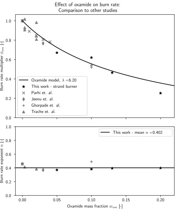
5.4.2 Comparison to other studies of the effect of oxamide on burn rate . . . 78
5.5 Results: minimum burn pressure . . . 80
5.6 Results: soot in combustion products . . . 81
5.7 Conclusions regarding propellant development . . . 83
6 Motor case design and materials considerations 85 6.1 Motor case design considerations . . . 86
6.1.1 Baseline motor case design . . . 88
6.1.2 Motor axial taper . . . 90
6.1.3 Manufacturing . . . 91
6.2.1 Material selection for tension-loaded structures . . . 95
6.2.2 Material selection for bending-loaded structures . . . 96
6.2.3 Other material selection considerations . . . 98
6.2.4 Material recommendations . . . 98
7 Research motor testing 99 7.1 Propellant mixing and casting . . . 99
7.2 Research motor . . . 100
7.2.1 Test facility . . . 101
7.2.2 Research motor design . . . 102
7.3 Research motor instrumentation . . . 108
7.3.1 Chamber pressure . . . 108
7.3.2 Thrust . . . 110
7.3.3 Case temperature . . . 116
7.3.4 Cameras . . . 116
7.3.5 Data logger . . . 116
7.4 Motor testing results . . . 117
7.4.1 Thrust and chamber pressure measurements . . . 117
7.4.2 Research motor burn rate measurements . . . 120
7.4.3 Operation at low thrust/burn area ratio . . . 125
7.4.4 Characteristic velocity measurements . . . 125
7.4.5 Thrust coefficient measurements . . . 128
7.4.6 Nozzle clogging . . . 129
7.4.7 Pressure spikes . . . 136
8 Motor case thermal protection 139 8.1 Ablative materials for thermal protection . . . 141
8.2 Thermal protection used in this work . . . 142
8.3 Models of heat transfer to the motor case . . . 144
8.3.2 Heat flux through the thermal protection layers . . . 155
8.3.3 Hot gas energy loss . . . 160
8.4 Ablation and char depth in the research motor . . . 163
8.4.1 Char depth measurements . . . 163
8.4.2 Char depth fits . . . 167
8.4.3 Alterations in char structure due to inhibitor layer . . . 169
8.4.4 Effects of acceleration and vibration on char . . . 170
8.4.5 Liner buckling . . . 171
8.5 Heat transfer and liner effectiveness measurements in the research motor173 8.5.1 Case temperature and heat flux measurements . . . 173
8.5.2 Hot gas energy loss measurements . . . 178
8.6 Recommendations for further thermal protection development . . . . 181
8.6.1 Design recommendations . . . 181
8.6.2 Experiment recommendations . . . 181
8.6.3 Modeling recommendations . . . 182
9 Nozzle mechanical and thermal design 185 9.1 Design challenges for small, long-burn-time nozzles . . . 185
9.1.1 Conventional nozzle thermal design techniques . . . 187
9.1.2 Small, long-burn time nozzles with steady-state ceramic insu-lation . . . 196
9.2 Nozzle heat transfer boundary conditions . . . 198
9.2.1 Internal hot gas thermal boundary . . . 198
9.2.2 External thermal boundary . . . 214
9.3 Nozzle thermal simulation . . . 215
9.3.1 Model description . . . 216
9.3.2 Prediction of nozzle shell temperatures in flight conditions . . 217
9.4 Nozzle testing . . . 219 9.4.1 Comparison of shell temperature measurements to thermal model220
9.4.2 Damage to boron nitride nozzle insert . . . 222 9.5 Recommendations for further nozzle development . . . 225 9.5.1 Nozzle testing and modeling recommendations . . . 225 9.5.2 Nozzle design recommendations: base diameter trade-offs . . . 225
10 Ceramic nozzle insulation 229
10.1 Thermal stress issues in ceramic insulators . . . 230 10.1.1 Example of failure due to thermal stress . . . 231 10.1.2 The thermal shock resistance parameter for comparing materials233 10.1.3 Thermal shock resistance of common engineering ceramics . . 234 10.2 Cellular ceramic insulation . . . 236 10.3 Modeling thermal stresses and heat transfer in cellular ceramic insulation237 10.3.1 Honeycomb mechanics theory . . . 237 10.3.2 Finite element model of thermal stresses . . . 242 10.3.3 Thermal conductivity of ceramic honeycomb insulation . . . . 249 10.4 Producing cellular ceramic insulation . . . 252 10.4.1 Effect of sintering process on material properties of fused silica 253 10.5 Nozzle insert material . . . 254 10.6 Tests of the ceramic insulation . . . 257 10.6.1 Torch test method for preliminary evaluation of nozzle materials257 10.6.2 Failed tests with graphite nozzle inserts . . . 258 10.6.3 Successful test with boron nitride insert . . . 262 10.7 Recommendations for further ceramic insulation development . . . 262
11 Conclusion 265
A Methods of estimating burn rate from motor firings 269
A.1 Method 1: average burn rate and 𝑛-averaged chamber pressure . . . . 270 A.2 Method 2: 𝑐*-based burn rate . . . 271
Chapter 1
Introduction
1.1
Motivation: the small and fast aircraft
capabil-ity gap
A gap exists in the size and capability of flight vehicles: no small vehicles are capable of sustained level flight at high speed. The small and fast gap is illustrated by fig. 1-1, which plots the speed and size of some U.S. military aircraft. Speed and mass are plotted on logarithmic axes, so that a variety of aircraft, from tiny uncrewed aerial vehicles (UAVs) to fighter jets, can be included in a single plot. Broad categories of air vehicles are indicated as gray patches. This figure focuses on aircraft which can sustain flight for a duration of a few minutes or more (although a few shorter-duration missiles are included). Longer flight duration enables more interesting missions.
There is a gap which the existing aircraft classes do not cover 1 : small, fast
aircraft with speed above 100 m s−1 and mass below 10 kg. This undeveloped regime
appears in the upper left of fig. 1-1. Small, fast aircraft in this regime would be useful for many valuable missions. This thesis is part of a research effort by MIT and its partners to develop a new class of small, fast aircraft.
One significant challenge for small, fast aircraft is that current propulsion systems
1Some small hobby rockets, sounding rockets and munitions do have speeds and masses in this
Figure 1-1: The speed vs. size design space currently lacks small, fast aircraft. The mass axis uses maximum takeoff mass for aircraft, and launch mass (incl. payload and propellant) for missiles. Data from [36, 37, 78, 1, 80, 92].
do not fit the power needed for high-speed flight into a small package. The focus of this thesis is to address this propulsion need by developing a new class of miniature slow-burn solid rocket motors.
First, let us briefly examine the current landscape of air vehicle propulsion. Four major propulsion technologies are used in the contemporary air vehicles listed in fig. 1-1:
1. Electric motors / propellers, which are used almost exclusively on small UAVs with low flight speeds,
2. Reciprocating engines / propellers, which are used on medium to large UAVs with flight speeds up to 70 m s−1,
3. Turbine engines, which are used on large, fast combat aircraft, cruise missiles, and UAVs, and
4. Solid rockets, which are used on fast, medium-sized missiles.
The speed and size regimes in which these technologies have been applied are shown in fig. 1-1. Of these technologies, only the turbine engine or the solid rocket motor appear to be technically feasible for small, fast aircraft. The solid rocket motor was selected as the propulsion technology for this investigation due to its high specific power and low mechanical complexity.
Small, fast aircraft have different thrust and endurance requirements than typical applications of solid rocket motors: the rocket motor must deliver a low thrust level (just enough to counter drag) for a few minutes. In contrast, typical solid rockets are optimized to deliver their impulse quickly, either to catch up with a target (i.e. tactical missiles) or reduce gravity losses (i.e. sounding rockets and launch vehicles). Most small (kilogram-scale) solid rocket motors only burn for a few seconds, not the few minutes desired here. Further, motors for small aircraft have thrust levels which are unusually low, even relative to the size of the motor. The (thrust / burn area) ratio is a measure of thrust relative to motor size; these motors have (thrust / burn area) ratio 1/10th that of typical solid rocket motors. Adapting solid rockets to the needs of small aircraft motivates the development of slow-burning solid propellants and a compact, long-burn-time rocket motor.
The following section presents an example design for a small, fast aircraft using rocket propulsion. The contribution of this thesis is to identify and solve technology challenges for these aircraft’s propulsion systems. These challenges and contributions are introduced in section 1.3.
1.2
Example concept for a small, fast aircraft
This section introduces an example design for a small, fast aircraft using rocket propulsion. This aircraft concept, called ‘Firefly’, is a representative example from
the middle of the unexplored region shown in fig. 1-1. The Firefly aircraft serves as a reference case for many of the issues examined in this thesis.
The design goals of the Firefly vehicle concept are:
1. Cruise at Mach 0.8, after dropping from a host aircraft at an altitude of 10 km. 2. Fit in a 70 mm × 70 mm × 480 mm bounding box, when stowed before drop. 3. Maximize range and endurance, ideally providing several minutes of powered
flight.
Firefly is a deployable UAV; it is designed to launch from a larger host aircraft in transonic flight, as illustrated in fig. 1-2. After launch, Firefly would unfold its wing and tails, stabilize, then ignite its rocket motor for powered flight. The nominal mission is steady level cruise (powered flight) at Mach 0.8 and 10 km altitude. After motor burnout, the vehicle would glide for some time.
Drop Unfold and stabilize
Ignite rocket Powered flight (2-3 minutes) Glide Discard stabilizer Design goals: • Cruise at Mach 0.8 • Size < 70 x 70 x 480 mm • Maximize range and endurance
F/A-18 Image: McDonnell Douglas
Disposal 70 mm (2.75 in) 480 m m (19 .0 in )
Figure 1-2: The nominal mission considered in this work is air-launch at 10 km altitude, followed by powered cruise at Mach 0.8.
A baseline reference design for Firefly is shown in fig. 1-3. The aircraft’s fuselage is 460 mm long. The motor case, made of titanium alloy, is the primary structure of
the fuselage. The motor case is filled with solid propellant (pink). The propellant burns from the aft end towards the front. As the propellant burns, the inside of the motor case would be exposed to hot combustion gas; to avoid this, an ablative material (black) lines the inside of the motor case. The ablative liner protects the motor case from hot combustion gas. The ablative is thicker at the aft of the motor, where it is exposed to hot combustion gas for a longer time. A wing is attached to the motor case; the wing rotates about a pivot to fold and fit into the deployment canister. The control surfaces also fold. The fuselage is configured with the payload mounted in front of the motor, and the motor has a circular cross section.
Payload (front) Propellant Nozzle Folding canard control surfaces Folding wing Motor case Ablative liner Folding tails (not actuated)
Figure 1-3: Baseline design of a small, fast aircraft with rocket propulsion.
The baseline design presented here is version 3 of the Firefly design. An earlier design iteration (version 1) was presented in the author’s MS thesis [89].
1.3
Technology challenges for small, fast aircraft
propul-sion
Solid rocket motors for small, fast aircraft propulsion operate at much lower thrust and for much longer burn times than conventional small solid rocket motors. This imposes unique demands on the motor and the propellant. The propellant must burn slowly and be able to operate at unusually low chamber pressures. The propellant burn rate should be adjustable2, so that a single propellant ‘family’ can accommodate
a range of mission and aircraft concepts. The motor case design is coupled to the fuselage and propellant grain design. The motor case must store as much propellant as possible and also provide mounting locations for the payload and control surfaces which will not get too hot. The inside of the motor case requires thermal protection from 1500–2200 K combustion gas for a few minutes. The thermal protection layers must be thin to minimize the use of valuable volume within the small motor. The nozzle is so small that conventional thermal designs will not work for the long burn time. It requires novel applications of insulating materials which tolerate extreme temperatures and thermal stresses.
This thesis investigates these technical challenges and solution options. A fam-ily of slow-burn propellants was developed, two motor case configurations were in-vestigated, and a novel ceramic-insulated nozzle was designed. Experiments were conducted to characterize the propellant, demonstrate a low thrust motor, measure ablation in the context of this motor, and test new nozzle designs and materials. Models were developed for the propellant burn rate, motor design, heat transfer within the motor and nozzle, and for thermal stresses in the nozzle insulation.
The results of this work advance the key technologies needed for small, slow-burn rocket motors. Specifically, the contributions of this thesis are:
1. For the design of small, low-thrust motors, this thesis identifies unusually low (thrust / burn area) ratio as a key challenge, shows that low (thrust / burn
area) requires slow-burn propellant and low chamber pressure, and quantifies the lower limits on the (thrust / burn area) ratio.
2. For slow-burn propellants, this thesis quantifies the effect of oxamide (a burn rate suppressant) on burn rate. Oxamide was previously known as a burn rate suppressant, but previous work in the open literature did not include burn rate measurements at conditions relevant to this work (high oxamide contents of 10-20% and low pressures of 0.1–2 MPa), and did not provide a quantitative model of oxamide’s effect on burn rate. This thesis presents new measurements for the burn rates of propellants with up to 20% oxamide content, and a model of oxamide’s effect on burn rate.
3. For the operation of small, low-thrust motors, this thesis demonstrates motor operation at low (thrust / burn area), and identifies low 𝑐* and 𝐶
𝐹 efficiencies
(of about 85%) as intrinsic features of small, low-thrust motors. Also, nozzle clogging and pressure spikes are identified as technical risks.
4. For motor case thermal protection, this thesis measures ablation and models heat transfer under the unusual conditions of these motors. It was discovered that combustion gas primarily transfers heat to the walls by radiation, and that the combustion gas is cooled significantly by this heat loss. These are unusual phenomena which occur due to the motor’s small size and low thrust.
5. For the nozzle, this thesis identifies the thermal challenges posed by small size and long burn time and presents a novel ceramic-insulated nozzle for small, long-burn motors. The ceramic-insulated nozzle design is supported by mod-eling and demonstration in a motor firing.
The experimental results and models enable engineers to design and predict the performance of solid rocket motors for small, fast aircraft. It is hoped that this thesis will help unlock a new option for aircraft propulsion by providing insight into the physics of these motors.
1.4
Overview of this thesis
Chapter 2 provides an overview of rocket motor and solid propellant technology. The body of this thesis is then arranged around the technical challenges described above. The lower limit on a motor’s thrust, and the performance of low-thrust motors are discussed in chapter 3. Theory and experimental work on slow-burn propellants are presented in chapters 4 and 5. Options for motor case and fuselage design are explored in chapter 6. Test firings of a research motor are reported in chapter 7. The design, modeling and testing of the motor case’s thermal protection is described in chapter 8. Finally, the nozzle and its ceramic insulation are discussed in chapters 9 and 10.
Chapter 2
Overview of solid propellant rockets
2.1
Typical practices for solid rocket motors
Solid propellant rockets have a long history, and in the last half-century advances in science and industrial practices have enabled solid rocket motors to be a reliable and performant solution for space launchers and missiles. The first black powder rockets were fielded by the Chinese (13th century), the India kingdom of Mysore (18th century) and the British (19th century) [53]. Double base propellants 1 were
developed in the late 1800s and early 1900s [90]. They are still used in some mili-tary applications requiring low smoke, but have largely been superseded by higher-performance composite propellants [77]. Composite propellants consist of particles of solid oxidizer bound by a polymer fuel matrix. The first castable composite pro-pellants were developed at Caltech’s Guggenheim Aeronautical Laboratory (which would later form the Jet Propulsion Laboratory, JPL) in 1942 [34]. Three companies with ties to JPL – Aerojet General Corporation, Thiokol Chemical Corporation, and United Technology Corporation – made major advances in the following years [34]. By the 1970s, the now-standard combination of hydroxyl-terminated polybutadiene (HTPB) binder and ammonium perchlorate (AP) oxidizer had been developed, and
1Double base propellants consist of solid nitrocellulose gelatinized with a liquid energetic nitrate
Figure 2-1: Solid propellant performance history. Reprinted from [86]. solid propellants reached a high level of performance (see fig. 2-1). Major advances in nozzle and motor case design were also made, mostly due to advances in materials. Parallel solid propulsion work was also undertaken in France and the former Soviet Union, although the Russians have not used solid propulsion in as many strategic or space applications as the United States. In the US today, the major solid propul-sion enterprises are Aerojet Rocketdyne and Northrop Grumman Innovation Systems (formerly Orbital ATK) [87].
Throughout this history, best practices have been accumulated for the safe and reliable development, production and operation of solid rocket motors. Much of this knowledge is proprietary (or classified), but useful resources are available in the open literature. As with most things relating to rocketry, Rocket Propulsion Elements [77] is the standard introductory reference. Solid Rocket Propulsion Technology by Alain Davenas [19] and Propellants and Explosives by Naminosuke Kubota [43] provide more details.
Low-thrust motors and slow-burn solid propellants are somewhat neglected areas of research. To the author’s knowledge, no solid rocket motors have been designed
with the low thrust, small size and long burn time achieved in this work.
2.2
Solid rocket motor overview
Solid propellant rocket motors store propellant as a solid grain within the combustion chamber. When the motor is ignited, the surfaces of the propellant grain burn and produce hot gas, which is expelled from the chamber through a nozzle to produce thrust. The main components of the motor are illustrated in fig. 2-2.
propellant Thrust set to
match drag
Burn area fixed by fuselage diameter
Nozzle throat area (free variable) Propellant composition
(free variable)
Figure 2-2: In designing an end-burn motor, the propellant composition and throat area are the free variables used to set the thrust and chamber pressure.
2.2.1
Thrust, chamber pressure and propellant burn rate
The motor is designed to produce some required amount of thrust – in this case, to match the drag on the aircraft. The thrust depends on the mass flow rate of propellant. However, the flow of propellant into the combustion chamber cannot be regulated – all of the propellant is loaded into the combustion chamber when the motor is assembled. Instead, the mass flow rate and thrust depend on how quickly the propellant burns (burn rate), and how large a surface area of propellant
is burning (burn area). The burn area is fixed by the motor diameter for an end-burn motor2. The burn rate depends on the propellant composition and the pressure
in the combustion chamber. The nozzle throat area helps set the chamber pressure. Thus, the propellant composition and throat area are the free variables for the design of an end-burn motor.
The chamber pressure and mass flow are set by an equilibrium between the nozzle mass flow and the combustion mass flow. This equilibrium is illustrated in fig. 2-3. The nozzle mass flow increases linearly with pressure and is shown as a black dashed line. If the nozzle throat area were smaller, the slope of this line would be shallower. The combustion mass flow (for a typical, fast-burn propellant) is shown as an orange curve. The combustion mass flow increases with pressure, but the trend is sub-linear3. At some pressure, the combustion is equal to the nozzle mass flow – this is a
stable equilibrium pressure at which the motor will operate. A slow-burn propellant will yield a lower combustion mass flow (blue curve) and will cause the motor to operate at a lower chamber pressure (if the nozzle throat area is held constant).
By adding different amounts of burn rate suppressant, a designer can adjust the burn rate of the propellant and set the thrust of the motor. For the very low thrust levels needed here, the motor will need a slow-burn propellant and a low chamber pressure. Thus, slow burn propellants are important to this work. Chapter 4 de-scribes how the burn rate can be reduced, and chapter 5 dede-scribes the characterization of a family of slow-burn propellants.
In addition to using a slow-burn propellant, the burn rate and thrust are reduced by designing the motor to operate at a lower chamber pressure. Thus, the motors in this work have low chamber pressure. However, the chamber pressure cannot be too
2An end-burn motor burns a solid propellant grain from the nozzle end towards the forward
end. Alternatively, a core-burn motor burns a hollow propellant grain from the core outwards. End burn motors are used in this work to give low thrust and long burn time. Core-burn motors give higher thrust, and are the more common design in other applications.
3For stable motor operation, the combustion mass flow must increase sub-linearly with chamber
pressure. If the combustion mass flow increased super-linearly with chamber pressure, the equilib-rium in fig. 2-3 would be unstable. In this case, the motor would not operate at a stable equilibequilib-rium pressure – it would either extinguish itself or explode. See Sutton and Biblarz [77], Example 12-1.
Mass
fl
ow
ሶ
𝑚
Chamber pressure 𝑝
𝑐 Propellantdoes not burn Explosion
Nozzle mass flow (set by throat area)
Fast-burn propellant Slow-burn propellant High thrust equilibrium Low thrust equilibrium Intermediate burn rates
Figure 2-3: The chamber pressure and mass flow are set by an equilibrium between the nozzle mass flow and the combustion mass flow. A slower burning propellant causes the motor to operate at a lower chamber pressure, lower mass flow and lower thrust.
low: for some propellants there is a minimum pressure below which the propellant will not burn. This sets a lower limit on the (thrust / burn area) ratio the motor can achieve, and is discussed further in chapter 3.
Mathematically, the (equilibrium) chamber pressure is: 𝑝𝑐=
𝐴𝑏
𝐴𝑡
𝜌𝑠𝑐*𝑟(𝑝𝑐) (2.1)
where 𝐴𝑏 is the burn area, 𝐴𝑡 is the throat area, 𝜌𝑠 is the propellant density, 𝑐*
is the characteristic velocity of the propellant (see section 2.2.3.3) and 𝑟(𝑝𝑐) is the
pressure-dependent burn rate of the propellant (with dimensions of velocity). 𝜌𝑠, 𝑐*
The thrust force of the motor is: 𝐹 = 𝐶𝐹 (︂ 𝑝𝑒 𝑝𝑐 ,𝑝𝑎 𝑝𝑐 , 𝛾 )︂ 𝐴𝑡𝑝𝑐 (2.2) where 𝐶𝐹 (︁ 𝑝𝑒 𝑝𝑐, 𝑝𝑎
𝑝𝑐, 𝛾)︁ is the thrust coefficient, a dimensionless parameter which
de-pends on the expansion of gas through the nozzle (see section 2.2.3.2).
2.2.2
Relation of motor efficiency to aircraft range
In addition to providing the required thrust, the motor should be efficient so that the aircraft has long range. An aircraft with longer range is desirable, as it can perform more missions.
The Breguet range equation predicts the powered-flight range 𝑅𝑝𝑜𝑤𝑒𝑟𝑒𝑑 of an
air-craft in steady, level flight:
𝑅𝑝𝑜𝑤𝑒𝑟𝑒𝑑 = 𝑣𝑐𝑟𝑢𝑖𝑠𝑒 𝐿 𝐷ln (︂ 𝑚𝑖𝑛𝑖𝑡 𝑚𝑓 𝑖𝑛𝑎𝑙 )︂ 𝐼𝑠𝑝 (2.3)
where 𝑣𝑐𝑟𝑢𝑖𝑠𝑒 is the (constant) flight speed, 𝐿/𝐷 is the aircraft’s lift to drag ratio (at
𝑣𝑐𝑟𝑢𝑖𝑠𝑒), 𝑚𝑖𝑛𝑖𝑡 is the initial mass (with propellant) and 𝑚𝑓 𝑖𝑛𝑎𝑙 is the final mass (after
all propellant has been burned). 𝐼𝑠𝑝 is the specific impulse, which measures the ‘fuel
efficiency’ of the propulsion system (and has units of seconds).
Aircraft which fly at a high altitude, like the Firefly concept, have a significant glide range in addition to the powered flight range. Depending on the mission, the extra glide range may or may not be useful.
To have long range, the aircraft should have high 𝐿/𝐷 (good aerodynamic design), high 𝑚𝑖𝑛𝑖𝑡/𝑚𝑓 𝑖𝑛𝑎𝑙 (good structural design), and high 𝐼𝑠𝑝 (an efficient motor). Specific
impulse is defined and discussed in the following section. The mass ratio depends somewhat on the motor case design, which is discussed in chapter 6.
2.2.3
Rocket motor performance parameters
This section describes three important performance metrics for rocket motors: the specific impulse 𝐼𝑠𝑝, thrust coefficient 𝐶𝐹, and characteristic velocity 𝑐*. Specific
impulse measures the ‘fuel efficiency’ of the motor, and depends on both 𝐶𝐹 and 𝑐*.
The thrust coefficient measures the effectiveness of the nozzle, and depends primarily on the nozzle pressure ratio. The characteristic velocity measures the ‘energetic-ness’ of propellant combustion, and depends primarily on the combustion gas temperature. These parameters are used in almost all rocket propulsion literature; details and derivations can be found in Sutton and Biblarz [77], chapter 3.
The ‘ideal’ values of all three parameters can be calculated from the theory of isentropic, 1-dimensional channel flow through a nozzle. For a particular motor, the actual values of these parameters are measured in motor firing experiments. The measured values are less than the ideal values due to inefficiencies. The ideal formulas and measurement techniques for each parameter are discussed below.
2.2.3.1 Specific impulse
The ‘fuel efficiency’ of the motor is measured by the specific impulse, 𝐼𝑠𝑝:
𝐼𝑠𝑝 ≡ 1 𝑔0 𝐹 ˙ 𝑚 = 1 𝑔0 𝐶𝐹𝑐* (2.4)
For historical reasons, specific impulse is normalized by the constant 𝑔0 ≡ 9.806 65 m s−2,
and has units of seconds. Typical values for solid-propellant rocket motors are 150– 270 s (see fig. 2-1). The right-most term in eq. (2.4) shows that specific impulse is the product of nozzle effectiveness (measured by 𝐶𝐹, section 2.2.3.2) and propellant
‘energetic-ness’ (measured by 𝑐*, section 2.2.3.3).
Higher specific impulse increases the range 𝑅 of a rocket-powered vehicle:
∙ For ballistic trajectories 4, 𝑅 ∼ 𝐼2 𝑠𝑝
It is desirable to design an efficient motor with high 𝐼𝑠𝑝.
Ideal formula The ideal specific impulse is calculated as:
𝐼𝑠𝑝,𝑖𝑑𝑒𝑎𝑙 =
1 𝑔0
𝐶𝐹,𝑖𝑑𝑒𝑎𝑙𝑐*𝑖𝑑𝑒𝑎𝑙 (2.5)
where 𝐶𝐹,𝑖𝑑𝑒𝑎𝑙 is given by eq. (2.11) and 𝑐*𝑖𝑑𝑒𝑎𝑙 by eq. (2.14). If the nozzle exit pressure
(𝑝𝑒) is equal to the ambient pressure (matched expansion), then:
𝐼𝑠𝑝,𝑖𝑑𝑒𝑎𝑙 = 1 𝑔0 ⎯ ⎸ ⎸ ⎷ 2𝛾 𝛾 − 1 ℛ𝑇𝑐 ℳ [︃ 1 −(︂ 𝑝𝑒 𝑝𝑐 )︂(𝛾−1)/𝛾]︃ (2.6) where ℛ is the universal gas constant, 𝑇𝑐 is the exhaust gas temperature, ℳ is the
exhaust gas molar mass and 𝛾 is the exhaust gas ratio of specific heats. To have high 𝐼𝑠𝑝, the exhaust gas should be hot, the exhaust gas molar mass should be low, and
the chamber pressure should be high (relative to the exit pressure).
Experimental measurement The actual specific impulse is determined by
mea-suring the thrust and mass flow rate, and using eq. (2.4). For solid rocket motors, it is often difficult to measure the instantaneous mass flow rate, so the time-averaged specific impulse is used 5:
⟨𝐼𝑠𝑝,𝑚𝑒𝑎𝑠⟩ = 1 𝑔0𝑚𝑝 ∫︁ 𝑡𝑒𝑛𝑑 𝑡𝑠𝑡𝑎𝑟𝑡 𝐹 𝑑𝑡 (2.7) where ∫︀𝑡𝑒𝑛𝑑
𝑡𝑠𝑡𝑎𝑟𝑡𝐹 𝑑𝑡 is the total impulse, and 𝑚𝑝 =
∫︀𝑡𝑒𝑛𝑑
𝑡𝑠𝑡𝑎𝑟𝑡𝑚𝑑𝑡˙ is the total mass of
pro-pellant burned between 𝑡𝑠𝑡𝑎𝑟𝑡 and 𝑡𝑒𝑛𝑑.
4For a ballistic trajectory (ignoring drag) 𝑅 ∼ 𝑣2
0≈ (Δ𝑣)
2, where 𝑣
0 is the velocity at burnout
and Δ𝑣 is the change in velocity delivered by the rocket motor. The Tsiolkovsky rocket equation states that Δ𝑣 ∼ 𝐼𝑠𝑝.
5This definition of ⟨𝐼𝑠𝑝,𝑚𝑒𝑎𝑠⟩ is equal to (︁ ∫︀𝑡𝑒𝑛𝑑 𝑡𝑠𝑡𝑎𝑟𝑡𝐼𝑠𝑝𝑚𝑑𝑡˙ )︁ /(︁∫︀𝑡𝑒𝑛𝑑 𝑡𝑠𝑡𝑎𝑟𝑡𝑚𝑑𝑡˙ )︁
, i.e. the time-average of 𝐼𝑠𝑝weighted by the mass flow at each time.
Efficiency The specific impulse efficiency 𝜁𝐼𝑠𝑝 is the ratio of the measured and ideal
specific impulse:
𝜁𝐼𝑠𝑝 =
𝐼𝑠𝑝,𝑚𝑒𝑎𝑠
𝐼𝑠𝑝,𝑖𝑑𝑒𝑎𝑙 (2.8)
where 𝐼𝑠𝑝,𝑖𝑑𝑒𝑎𝑙 is calculated using the actual ambient pressure at which the motor was
fired.
The specific impulse efficiency is the product of the thrust coefficient efficiency (which will be defined in eq. (2.12)) and characteristic velocity efficiency (eq. (2.16)):
𝜁𝐼𝑠𝑝 = 𝜁𝐶𝐹𝜁𝑐* (2.9)
The specific impulse efficiency 𝜁𝐼𝑠𝑝 is always less than 1, and losses are due to
inefficiencies in nozzle expansion (𝜁𝐶𝐹 < 1) and inefficiencies in combustion (𝜁𝑐* < 1).
Characterizing these inefficiencies is important to accurately predict the performance of the motor and the range of the vehicle.
2.2.3.2 Thrust coefficient
The thrust coefficient 𝐶𝐹 is a dimensionless parameter which represents the
effec-tiveness of the nozzle expansion process. It is defined as: 𝐶𝐹 ≡
𝐹 𝐴𝑡𝑝𝑐
(2.10) The thrust coefficient ranges from about 0.8 to 1.9 for typical rockets [77]; higher values are preferred.
Ideal formula The thrust coefficient depends on the chamber pressure 𝑝𝑐, exit
ratio of specific heats 𝛾. For an ideal nozzle: 𝐶𝐹,𝑖𝑑𝑒𝑎𝑙 = ⎯ ⎸ ⎸ ⎷ 2𝛾2 𝛾 − 1 (︂ 2 𝛾 + 1 )︂(𝛾+1)/(𝛾−1)[︃ 1 −(︂ 𝑝𝑒 𝑝𝑐 )︂(𝛾−1)/𝛾]︃ + 𝑝𝑒− 𝑝𝑎 𝑝𝑐 𝐴𝑒 𝐴𝑡 (2.11) The parameters on the right-hand side are not independent: the nozzle pressure ratio 𝑝𝑐/𝑝𝑒 is set by the nozzle expansion ratio 𝐴𝑒/𝐴𝑡.
For a given 𝑝𝑐, 𝐶𝐹 is maximized when 𝑝𝑒 = 𝑝𝑎, a condition known as matched
expansion. Often, the nozzle expansion ratio 𝐴𝑒/𝐴𝑡 is chosen so that 𝑝𝑒 will equal
the ambient pressure at the expected operating altitude.
For the motor designs in this work, it is assumed that the nozzle expansion ratio is always chosen to give matched expansion at the nominal chamber pressure. Thus, 𝑝𝑒 is fixed to equal 𝑝𝑎, and 𝐴𝑒/𝐴𝑡 is set by the choice of 𝑝𝑐. Further, 𝛾 is set by
the propellant chemistry, and does not depend on the motor design. Under these assumptions, 𝑝𝑐 is the only free variable in determining 𝐶𝐹, and one can think of 𝐶𝐹
as a function primarily of 𝑝𝑐, 𝐶𝐹(𝑝𝑐).
Assuming the nozzle is always designed for matched expansion, 𝐶𝐹 increases
monotonically with 𝑝𝑐 (fig. 2-4); thus higher chamber pressures are desirable. Low
thrust motors (which operate at low chamber pressure) will have low 𝐶𝐹.
Note that 𝐶𝐹 does not depend on the temperature of the combustion gas. Thus,
𝐶𝐹 represents the contribution of nozzle expansion to specific impulse, whereas 𝑐*
(which does depend on 𝑇𝑐, see section 2.2.3.3) represents the contribution of
com-bustion to specific impulse. Together, 𝐼𝑠𝑝 = 𝐶𝐹𝑐*/𝑔0.
Experimental measurement In motor firings, 𝐶𝐹 is determined by measuring
100 101 102 103 104 Nozzle pressure ratio 𝑝𝑐/𝑝𝑒[-]
0.0 0.5 1.0 1.5 2.0 Thrust co efficient 𝐶𝐹 [-] Limit at 𝑝𝑐/𝑝𝑒→ ∞
Ideal thrust coefficient matched expansion, 𝛾 = 1.25
Figure 2-4: The thrust coefficient is higher if the chamber pressure 𝑝𝑐is high relative
to the nozzle exit pressure 𝑝𝑒.
Efficiency The 𝐶𝐹 efficiency 𝜁𝐶𝐹 is the ratio of the measured and ideal thrust
coefficients:
𝜁𝐶𝐹 =
𝐶𝐹,𝑚𝑒𝑎𝑠
𝐶𝐹,𝑖𝑑𝑒𝑎𝑙
(2.12) The efficiency is less than 1, and in well designed nozzles it will be > 0.90 [77]. Reasons for reduced efficiency include:
∙ Divergence losses - a non-axial component of the nozzle exit velocity will reduce thrust and reduce 𝐶𝐹. The nozzles in this work use a conical exit with 15∘ half
angle; for this geometry the divergence losses are 1.7%.
∙ Viscous losses - viscous forces in the nozzle reduce the exit velocity. This is a more severe problem for smaller nozzles with lower Reynolds numbers.
∙ Multi-phase flow - solid particles in the exhaust reduce 𝐶𝐹. The propellants
used in this work produce about 2% by mass solid soot in the exhaust gas. ∙ Nozzle obstructions or surface damage - solid deposits obstructing the gas flow
through the nozzle or damage to the nozzle surfaces will increase losses in the nozzle.
A representative value of 𝜁𝐶𝐹 can be measured from motor firings, and then used
as a correction factor for similar nozzles.
2.2.3.3 Characteristic velocity
Characteristic velocity, 𝑐*, measures the propellant combustion process’s contribution
to specific impulse. The characteristic velocity 𝑐* is defined as:
𝑐* ≡ 𝐴𝑡𝑝𝑐 ˙
𝑚 (2.13)
For typical solid propellants, 𝑐* is between 1200 and 1600 m s−1 [77]. Higher
values are desirable.
Ideal formula The ideal value of 𝑐* is [77]:
𝑐*𝑖𝑑𝑒𝑎𝑙 = √︃ ℛ𝑇𝑐 𝛾ℳ (︂ 𝛾 + 1 2 )︂12(𝛾−1𝛾+1) (2.14) where ℛ is the universal gas constant, ℳ is the exhaust gas molar mass, and 𝑇𝑐 is
the (stagnation) temperature at the nozzle inlet. Note that 𝑐*is proportional to√
𝑇𝑐;
𝑐* is higher for hotter-burning, more energetic propellants. Also, the ideal value of 𝑐* does not depend on the chamber pressure or nozzle expansion process. Thus, 𝑐* is a figure of merit for the propellant and combustion process.
Experimental measurement The actual value of 𝑐* is measured in motor firing experiments. Characteristic velocity can be measured from 𝐴𝑡𝑝𝑐/ ˙𝑚 (the right-hand
side of eq. (2.13)). However, measuring the instantaneous mass flow rate in solid rocket motors is difficult. If instantaneous ˙𝑚 measurements are not available (as in this work), the time-averaged characteristic velocity can be used instead. It is
defined as 6: ⟨𝑐*𝑚𝑒𝑎𝑠⟩ = 𝐴𝑡 𝑚𝑝 ∫︁ 𝑡𝑒𝑛𝑑 𝑡𝑠𝑡𝑎𝑟𝑡 𝑝𝑐(𝑡)𝑑𝑡 (2.15)
Efficiency The departure of the actual value of 𝑐* from the ideal value is measured by the 𝑐* efficiency, 𝜁
𝑐*:
𝜁𝑐* ≡
𝑐*𝑚𝑒𝑎𝑠
𝑐*𝑖𝑑𝑒𝑎𝑙 (2.16)
The actual characteristic velocity is less than the ideal value because: ∙ Incomplete combustion reduces 𝑐*.
∙ Heat loss to the ablative liner and motor case reduces 𝑐*.
The actual 𝑐* is typically 90-99% of the theoretical value, but the exact value is
hard to predict. Thus, the actual 𝑐* must be measured in a motor under realistic
conditions. A typical value of 𝜁𝑐* can be found from these results and used as a
correction factor in the design of similar motors.
2.3
Solid propellant overview
A solid propellant contains both fuel and oxidizer mixed together. This is different from most other combustion systems, where the fuel and oxidizer are only mixed just before combustion (e.g. internal combustion engines, torches, liquid bi-propellant rocket engines). This poses a chemistry challenge: the propellant ingredients must react energetically with each other, but also be safely stored and handled while mixed together. A propellant must also not ignite when exposed to mechanical shock, heat or electrostatic discharges during handling. Finally, because the propellant burn rate
6This definition of ⟨𝑐* 𝑚𝑒𝑎𝑠⟩ is equal to (︁ ∫︀𝑡𝑒𝑛𝑑 𝑡𝑠𝑡𝑎𝑟𝑡𝑐 *𝑚𝑑𝑡˙ )︁/(︁∫︀𝑡𝑒𝑛𝑑 𝑡𝑠𝑡𝑎𝑟𝑡𝑚𝑑𝑡˙ )︁
, i.e. the time-average of 𝑐* weighted by the mass flow at each time.
determines the motor’s chamber pressure and thrust, the propellant must burn at a stable and predictable rate.
Composite propellants are heterogeneous mixtures of a crystalline oxidizer, a polymer binder, and possibly a metal fuel. The solid oxidizer and binder do not react with each other at room temperature, but when heated decompose (gasify) and undergo energetic gas-phase reactions. Ammonium perchlorate composite propellant (APCP) is the most-used composite propellant (e.g. the Space Shuttle’s Reusable Solid Rocket Motor, Orbital ATK’s Star motor series [60]). APCP is energetic (up to 270 seconds of specific impulse [77]), is resistant to accidental ignition, and will burn stably in a properly designed motor.
2.3.1
Composition of composite propellants
Composite propellants contain a solid oxidizer and (optionally) a powdered metal fuel, held together by a rubber-like binder (fig. 2-5). Usually, the solid oxidizer is ammonium perchlorate (NH4ClO4), although in some propellants other
oxygen-rich salts are used (e.g ammonium nitrate, NH4NO3). Ammonium perchlorate is
a crystalline solid, which is divided into small particles (10–500 µm) and dispersed though the propellant. During combustion, the solid oxidizer decomposes to pro-duce an oxygen-rich gas. A polymer matrix, the binder, binds the oxidizer particles together, giving the propellant mechanical strength. Hydroxyl-terminated polybuta-diene (HTPB) is a typical binder. The binder serves as a fuel, giving off hydrocarbon vapors during combustion. Additional fuel may be added as hot-burning metal pow-der dispersed in the binpow-der.
During propellant mixing, the other ingredients are added to the binder while the binder is in a liquid form, making a slurry. A curative is then added to cross-link the binder into a solid, solidifying the propellant. After the curative is mixed in, the propellant must be cast into the correct shape before the propellant solidifies (usually this takes a few hours).
Figure 2-5: A composite propellant consists of crystalline oxidizer particles, and possibly a metal fuel powder, dispersed in a polymer binder.
HX-752) promote better adhesion between the oxidizer particles and the binder, im-proving mechanical properties and stabilizing combustion. Antioxidants (e.g. CAO-5) improve the shelf life of the propellant. Plasticizers (e.g. IDP) make mixing and casting easier by improving the rheological properties of the propellant slurry. Burn rate suppressants (e.g. oxamide) or catalysts (e.g. Fe2O3) can be added to modify
the propellant’s burn rate.
Some propellants include an opacifier to make the propellant opaque and emis-sive. During combustion heat is transfered to the solid propellant by radiation. For good combustion, the propellant must be opaque so that the (infrared) radiation is absorbed at the burning surface, not deeper into the solid. If a large amount of metal fuel is used, this will make the propellant opaque. Propellants without metal fuel
often used carbon powder as an opacifier [51].
2.3.2
Combustion of composite propellants
The combustion process of a composite propellant has many steps, and the flame structure is complex (fig. 2-6). Although the propellant is a solid, important reac-tions, including combustion of the fuel with the oxidizer, occur in the gas phase. A set of flames hover over the surface of the burning propellant. These flames transfer heat to the propellant surface, causing its solid components to decompose into gases. The gaseous decomposition products contain fuel vapor and oxidizing species, which supply the flames with reactants.
Figure 2-6: The typical flame structure of composite propellant combustion. Heat from the flames decomposes the ammonium perchlorate and binder, which in turn supply oxidizing (AP) and fuel (binder) gases to the flames. Based on figures in [46, 66].
This flame structure causes the propellant to burn faster at higher pressures. At higher pressures, the gas phase is denser, causing reactions and diffusion to proceed more quickly. This moves the flame structure closer to the surface. The closer flames and denser conducting medium enhance heat transfer to the surface, which drives more decomposition, increasing the burn rate.
Although the dependence of burn rate on pressure is complicated, it can be empirically described by fitting a simple power law to experimental data (see sec-tion 2.3.3.2). The dependence of burn rate on pressure is important because it de-termines the chamber pressure and thrust of a solid rocket motor (recall section 2.2).
2.3.3
Solid propellant properties
This section defines several important properties of solid propellant. These include the solid density 𝜌𝑠 and pressure-dependent burn rate 𝑟(𝑝𝑐) which were introduced
in section 2.2 and are necessary to determine the equilibrium chamber pressure of a motor. Typical techniques for predicting and measuring these properties are also discussed.
2.3.3.1 Solid propellant density
The ideal density of the solid propellant is the weighted average of the densities of the propellant ingredients. The actual density of the propellant can be determined by weighing a sample of known volume. The actual density will be less than the ideal density if there are voids in the propellant.
2.3.3.2 Pressure-dependent burn rate
The pressure dependence of the propellant burn rate is typically modeled with Vieille’s formula:
where 𝑛 is the dimensionless burn rate exponent, and 𝑎 is the burn rate coefficient, which has dimensions of [velocity (pressure)−𝑛]. For stable operation in a motor, the
propellant burn rate must increase sub-linearly with pressure, i.e. 𝑛 < 1. For typical composite propellants, 𝑛 is between 0.2 and 0.5 [77].
𝑎 and 𝑛 are model parameters which must be determined experimentally. These can be measured by:
∙ Burning small strands of propellant at a controlled pressure in a ‘Strand Burner’ apparatus. Using several samples of the same propellant, the burn rate can be measured at several pressures. Then, values for 𝑎 and 𝑛 can be fit to this data. ∙ Firing the propellant in a motor with known 𝐴𝑏 and 𝐴𝑡, and measuring the
time to burn the propellant and the chamber pressure. 𝑎 and 𝑛 can be fit to data from one or several firings, depending on the details of the experiment. The Strand Burner experiment is easier to repeat over a range of chamber pres-sures, but the motor firing gives a more accurate prediction of what the burn rate will be in a similar motor. Both techniques are used in this work.
The burn rate also has a (weaker) dependence on the initial temperature of the propellant grain [77]. This was not measured in this work. All burn rate measure-ments in this work were at an initial temperature of 15–25∘C.
2.3.3.3 Minimum burn pressure
For some propellants, there is a minimum pressure below which the propellant will not burn. When oxamide is added to reduce the burn rate, the minimum burn pressure increases with oxamide content. The minimum burn pressure puts a lower limit on chamber pressure. As discussed in chapter 3, this has important implications for motor and vehicle design, setting a minimum feasible thrust for the motor.
2.3.3.4 Combustion gas ratio of specific heats
The expansion of the exhaust gas through the nozzle depends on the gas’s ratio of specific heats, 𝛾. Thus it is important to quantify 𝛾 for the gas.
The ratio of specific heats is predicted by combustion equilibrium software [65]. The ratio of specific heats will change slightly as the gas expands through the nozzle. The values presented here are for the chamber (stagnation) conditions; assuming the gas properties are ‘frozen’ at the chamber conditions is a good approximation for small nozzles [77].
The numerical predictions of 𝛾 are generally quite good [77], and measuring 𝛾 in the motor would be difficult, thus no empirical data for 𝛾 is presented in this work.
2.3.3.5 Other properties
Other properties of the propellant, e.g. mechanical properties, aging, thermal expan-sion, sensitivity to accidental ignition, etc., are also important for other aspects of solid rocket motor design. However, these other properties were not measured in this work.
Chapter 3
Low-thrust solid rocket motors for
aircraft propulsion
The design of slow-burn solid rocket motors for aircraft propulsion is coupled to the fuselage configuration and the desired trajectory. The motor’s thrust is set by the trajectory, and its burn area is set by the fuselage diameter. Inconveniently, the required thrust level is very low compared to the required burn area. The challenge of these slow-burn motors is not low thrust itself, but low thrust relative to the burn area.
The low (thrust / burn area) ratio is an unusual feature of motors meant to pro-pel an aircraft in steady, level flight. Typical solid rocket motors are designed to accelerate a vehicle quickly, either to catch up with a target (i.e. tactical missiles) or to reduce gravity losses (i.e. sounding rockets and launch vehicles). Most devel-opment efforts have focused on high thrust motors with high-energy, faster burning propellants. Operation at low thrust, in contrast, is a somewhat neglected area of research.
The thrust and burn area constraints of UAV propulsion require a slow-burn propellant. This motivated the development of a family of slow-burn propellants, which is discussed in chapter 4 and chapter 5. As will be shown in this chapter, even with slow-burn propellant, the efficiency of the motor (𝐼𝑠𝑝) is reduced by operating
at such a low thrust/burn area ratio.
3.1
The thrust/burn area ratio
This section introduces the thrust/burn area ratio, 𝐹/𝐴𝑏, as a parameter for motor
design. This parameter is seldom used in the propulsion literature. However, it is helpful for the design of slow-burn motors for aircraft propulsion because it provides a link between the motor design, fuselage configuration, and trajectory.
For the motors considered here, thrust and burn area are fixed by the aircraft and trajectory design. For steady, level flight the thrust is fixed to match the drag on the aircraft at cruise speed. For an end-burn motor which fills the fuselage, the burn area is set by the fuselage diameter.
For the reference Firefly mission (cruise at Mach 0.8, 10 km altitude), these con-siderations set a 𝐹/𝐴𝑏 ratio which is 1/10th the value of typical solid rocket motors.
In fact, the required 𝐹/𝐴𝑏 is very close to the lower limit at which the propellant
can operate.
3.1.1
Relation of the thrust/burn area ratio to motor design
To derive the relation of 𝐹/𝐴𝑏 to the other motor design parameters, we start with
two equations (see section 2.2): 1) thrust:
𝐹 = 𝑝𝑐𝐴𝑡𝐶𝐹(𝑝𝑐) (3.1)
and 2) mass flow equilibrium: ˙ 𝑚 = 𝑝𝑐𝐴𝑡 𝑐* ⏟ ⏞ nozzle = 𝐴𝑏𝑟𝜌𝑠 = 𝐴𝑏(𝑎𝑝𝑛𝑐)𝜌𝑠 ⏟ ⏞ combustion (3.2)
Motor Application Thrust Burn area 𝐹/𝐴𝑏
[N] [m2] [kPa]
First Stage, Minuteman Missile booster 865 581 24.84 34.8
Orbus-6 Upper stage 76 394 2.52 30.3
STAR 27 Upper stage 26 732 0.89 30.1
Cesaroni P38-6G Classic Hobby 325.3 0.0204 15.9
Cesaroni P38-2G Classic Hobby 125.1 0.0068 18.4
Table 3.1: Different solid rocket motors, with a wide range of sizes and applications, all operate at similar 𝐹/𝐴𝑏. Thrust and burn area are average values over the burn
time. All these motors use ammonium perchlorate composite propellant. Data from [77, 13].
Combining the two equations gives: 𝐹 𝐴𝑏
= 𝑝𝑛𝑐𝐶𝐹(𝑝𝑐)𝑐*𝑎𝜌𝑠 (3.3)
The 𝐹/𝐴𝑏 ratio depends on the chamber pressure and the properties of the
pro-pellant (𝑛, 𝑐*, 𝑎 and 𝜌
𝑠). 𝐹/𝐴𝑏 does not depend on the size of the motor. In fact,
table 3.1 shows that several motors, which differ in size (total impulse) by five orders of magnitude, have similar values of 𝐹/𝐴𝑏, all between 15 kPa and 35 kPa.
3.1.2
Relation of the thrust/burn area ratio to trajectory and
fuselage
The ratio 𝐹/𝐴𝑏 is related to the trajectory. In steady, level flight:
𝐹 = 𝐷 = 𝑞𝐶𝐷𝑆𝑟𝑒𝑓 (3.4)
where 𝑞 is the dynamic pressure, 𝐶𝐷 is the drag coefficient, and 𝑆𝑟𝑒𝑓 is the drag
reference area. For the purposes of this chapter, we will take 𝑆𝑟𝑒𝑓 to be the
Dividing both sides of eq. (3.4) by 𝐴𝑏 gives: 𝐹 𝐴𝑏 = 𝑞𝐶𝐷 (︂ 𝑆𝑟𝑒𝑓 𝐴𝑏 )︂ (3.5) Thus, 𝐹/𝐴𝑏 is proportional to the dynamic pressure, and to the ratio of drag
reference area over burn area. 𝑞 depends on the trajectory, and 𝑆𝑟𝑒𝑓/𝐴𝑏 depends on
how the motor is configured within the fuselage. For an end-burn motor, 𝐴𝑏 is the
transverse section area of the propellant grain. 𝑆𝑟𝑒𝑓 will be slightly larger, due to
the ablative liner and case wall which surround the propellant (fig. 3-1). Thus, for end-burn motors, 𝑆𝑟𝑒𝑓/𝐴𝑏 will be slightly greater than one. For the baseline design
shown in fig. 1-3, 𝑆𝑟𝑒𝑓/𝐴𝑏 = 1.2. 𝐴𝑏 𝑆𝑟𝑒𝑓 motor payload Side view Section view Section plane Front Back
Figure 3-1: The fuselage frontal reference area 𝑆𝑟𝑒𝑓 (shaded gray) is only slightly
larger than the propellant burn area 𝐴𝑏 (shaded red).
𝑆𝑟𝑒𝑓/𝐴𝑏 is only weakly dependent on the size of the vehicle. If the fuselage
diameter were increased, 𝑆𝑟𝑒𝑓/𝐴𝑏 would be closer to 1 – the burn area would increase,
but the thickness of the ablative would not change.
Thus, the three terms on the right-hand side of eq. (3.5) (𝑞, 𝐶𝐷, and 𝑆𝑟𝑒𝑓/𝐴𝑏),
are set by the trajectory and fuselage configuration. Together, they set a required value for the motor’s 𝐹/𝐴𝑏. As will be shown below, this value is inconveniently low.
Consider the 𝐹/𝐴𝑏 required by eq. (3.5) for the example Firefly mission (Mach 0.8,
10 km altitude). At Mach 0.8 and 10 km altitude, the dynamic pressure is 𝑞 = 12 kPa. At Mach 0.8, 𝐶𝐷 might be about 0.2, depending on the size of the wings and tails.
As discussed above, 𝑆𝑟𝑒𝑓/𝐴𝑏 = 1.2. The desired 𝐹/𝐴𝑏 for steady, level flight is about
This value is much lower than the typical values presented in table 3.1. In fact, it is almost at the lower limit of 𝐹/𝐴𝑏 that can be achieved, even with slow-burn
propellants.
3.2
Lower limit on thrust
There is a lower limit on 𝐹/𝐴𝑏 below which a propellant cannot operate. Thus,
there is a lower limit on the thrust of an end-burn motor (if the motor diameter is fixed). This is primarily because the motor must have a very low chamber pressure to achieve low 𝐹/𝐴𝑏, but below some minimum pressure the propellant will not burn.
Even with slow-burn propellants, 𝐹/𝐴𝑏 ratios less than about 2 kPa are not feasible.
As will be shown below, there is also a performance penalty to operating at low 𝐹/𝐴𝑏: the specific impulse is less if the motor is made to operate a lower 𝐹/𝐴𝑏.
The preceding sections showed that the example Firefly mission requires an end-burn motor which operates a 𝐹/𝐴𝑏 which is much lower than that of typical motors.
Some parameters of the motor design need to be changed to operate at low 𝐹/𝐴𝑏.
Revisiting eq. (3.3), note that 𝑝𝑛
𝑐 and 𝐶𝐹(𝑝𝑐) both decrease monotonically with
de-creasing 𝑝𝑐: 𝐹 𝐴𝑏 = 𝑝𝑛𝑐𝐶𝐹(𝑝𝑐) ⏟ ⏞ pressure-dependent 𝑐*𝑎𝜌𝑠 (3.6)
The remaining variables, 𝑐*𝑎𝜌
𝑠, depend only on the propellant composition, not
pressure. Thus, to make 𝐹/𝐴𝑏 small, the motor must operate at low 𝑝𝑐 and use a
slow-burn propellant with low 𝑎.
However, operating at low 𝑝𝑐reduces 𝐶𝐹 and 𝐼𝑠𝑝 (because the nozzle expansion is
less efficient when the pressure ratio across the nozzle is lower). Also, each propellant has a minimum pressure below which it will not burn.
This trend is illustrated in fig. 3-2 for several different propellants. Three pro-pellants are from the family of ammonium perchlorate (AP) propro-pellants developed
0 2 4 6 8 10 12 14 Thrust / burn area ratio 𝐹 / 𝐴𝑏 [kP a] Min. 𝐹/𝐴𝑏 for these propellants Min. 𝐹/𝐴𝑏 for these propellants
Firefly example mission Mach 0.8, 10 km AN propellant AP propellant baseline AP propellant 10% oxamide AP propellant 20% oxamide Min. 𝑝𝑐 fo r soni c flo w Min. 𝐹/𝐴𝑏 for these propellants Typical AP propellant rocket motors 𝐹/𝐴𝑏 = 15-35 kPa 0.0 0.5 1.0 1.5 2.0 2.5 3.0 Chamber pressure 𝑝𝑐 [MPa]
130 140 150 160 170 180 190 200 210 220 Sp ecific impulse 𝐼𝑠𝑝 (ideal) [s] AN propellant AP propellant baseline AP propellant 10% oxamide AP propellant 20% oxamide Min. 𝑝𝑐 fo r soni c flo w
Figure 3-2: Operating at lower 𝐹/𝐴𝑏 requires low chamber pressure and reduces
specific impulse. At some minimum 𝐹/𝐴𝑏, each propellant reaches its minimum
burn pressure (marked with ‘x’). Lower 𝐹/𝐴𝑏 is infeasible for that propellant.
in this work. In these propellants, the burn rate is set by the amount of oxamide (a burn rate suppressant). The baseline AP propellant (blue curve) burns fastest, the
10% oxamide propellant (pink curve) has an intermediate burn rate, and the 20% oxamide propellant (orange curve) burns slower. For comparison, an ammonium ni-trate (AN) propellant (green curve) is also included. Using AN oxidizer is a different way to make a slow burning propellant (see chapter 4).
The curves show 𝐹/𝐴𝑏 (top plot) and specific impulse (bottom plot) versus
cham-ber pressure. The relation between 𝐹/𝐴𝑏 and 𝑝𝑐 is calculated using eq. (3.3) and
propellant burn rate data measured in this work1. Specific impulse is calculated
us-ing the ideal 1d nozzle model, assumus-ing matched expansion to an ambient pressure of 30 kPa. These plots help to find a propellant and chamber pressure which meet a mission’s 𝐹/𝐴𝑏 requirement, while keeping 𝐼𝑠𝑝 as high as possible.
For each propellant, reducing chamber pressure reduces 𝐹/𝐴𝑏 (top plot).
How-ever, the chamber pressure cannot be less than the propellant’s minimum burn pres-sure; this sets a lower limit on 𝐹/𝐴𝑏 for that propellant. The minimum combustion
pressures for each propellant are marked with an ‘x’ in the top plot 2.
Although the AN propellant has the slowest burn rate, the AP+oxamide pro-pellants can operate at lower 𝐹/𝐴𝑏 because they have lower minimum combustion
pressures. The 10% oxamide propellant can provide an 𝐹/𝐴𝑏 down to 2.1 kPa.
In-terestingly, the slower-burning propellants (AP+20% oxamide and AN) have higher minimum 𝐹/𝐴𝑏 – although they are slower-burning, their minimum burn pressures
are much higher.
For each propellant, operating at lower chamber pressure reduces the specific impulse (bottom plot). As the exit pressure is always expanded to ambient (30 kPa), lower 𝑝𝑐reduces the nozzle pressure ratio, lowering 𝐼𝑠𝑝. At a given chamber pressure,
cooler-burning propellants give lower 𝐼𝑠𝑝.3
Looking across the top plot, notice that at a given 𝐹/𝐴𝑏, the slower-burning
pro-1For the AN propellant, 𝑎, 𝑛 are from Sutton and Biblarz [77] table 13-10 and the minimum
burn pressure is from Vernacchia [89].
2The AP baseline propellant curve is not marked with an ‘x’ because the minimum 𝑝𝑐 to choke
the nozzle flow is higher than the minimum burn pressure of this propellant.
3For the AP+oxamide propellants, adding more oxamide reduces the flame temperature and
pellants can operate at a higher chamber pressure. The 𝐹/𝐴𝑏 required for the Firefly
reference mission (Mach 0.8, 10 km altitude) is about 2.9 kPa and is marked on the top plot with a black dotted line. This is barely within the limits of the AP+oxamide propellants. The AN propellant cannot achieve this 𝐹/𝐴𝑏 – the required 𝑝𝑐 is so low
that it would not burn. At this 𝐹/𝐴𝑏, the baseline AP propellant would need such a
low 𝑝𝑐that the nozzle flow would barely reach sonic velocity, and the specific impulse
would be abysmal (< 130 s).
The 10% and 20% oxamide propellants can operate at the example mission 𝐹/𝐴𝑏.
For the 10% oxamide propellant, the motor would operate at 𝑝𝑐 = 0.21 MPa and
𝐼𝑠𝑝,𝑖𝑑𝑒𝑎𝑙 = 153 s; for the 20% oxamide propellant, 𝑝𝑐 = 0.55 MPa and 𝐼𝑠𝑝,𝑖𝑑𝑒𝑎𝑙 = 163 s.
These operating points are marked with dots on the bottom plot.
The effects of 𝐹/𝐴𝑏 on specific impulse are summarized in fig. 3-3. This plot
shows the same data as fig. 3-2, but plotted as 𝐼𝑠𝑝 versus 𝐹/𝐴𝑏. Generally, lower
𝐹/𝐴𝑏 reduces specific impulse, and slower-burning propellants give higher specific
impulse at a given 𝐹/𝐴𝑏.
For 𝐹/𝐴𝑏 > 3.1 kPa, the AN propellant can operate and has slightly higher
specific impulse than the AP+oxamide propellant (fig. 3-3). However, the AN pro-pellant is less dense (1480 kg m−3 vs. 1600 kg m−3) so less propellant mass can fit
in the motor. Also, for 𝐹/𝐴𝑏 > 4 kPa, the AN propellant requires high (> 3 MPa)
chamber pressures (fig. 3-2, top plot), which entail a heavy motor case. In contrast, the AP+oxamide propellant family can be used for a wide range of 𝐹/𝐴𝑏. Thus, the
AP+oxamide propellant family is preferred for this work.
These specific impulse values (e.g. 𝐼𝑠𝑝,𝑖𝑑𝑒𝑎𝑙 = 153 s for the example mission with
AP+10% oxamide propellant) are unusually low for modern solid rocket motors (𝐼𝑠𝑝 > 250 s is achievable). Further, small, low-thrust motors have low 𝑐* and 𝐶𝐹
efficiencies (as will be discussed in later chapters). These inefficiencies reduce the delivered 𝐼𝑠𝑝 to about 110 s. Despite this low 𝐼𝑠𝑝, an aircraft propelled by such
a motor can have a powered flight range of 50–100 km, which is useful for many missions.
0 2 4 6 8 10 12 14 Thrust / burn area ratio 𝐹/𝐴𝑏 [kPa]
130 140 150 160 170 180 190 200 210 220 Sp ecific impulse 𝐼𝑠𝑝 (ideal) [s] Firefly example mission Mach 0.8, 10 km AN propellant AP propellant baseline AP propellant 10% oxamide AP propellant 20% oxamide
Figure 3-3: Operating at lower 𝐹/𝐴𝑏 reduces specific impulse. Slower-burning
Chapter 4
Slow-burn solid propellant
Slow-burn propellants are necessary for small, low-thrust motors. Three routes to achieve a slow-burn propellant are: 1) change to an inherently slower-burning oxi-dizer, 2) use a larger oxidizer particle size, or 3) add a burn rate suppressant to the propellant. This work employs large oxidizer particles and a burn rate suppressant (oxamide).
Slow-burn solid propellants are a somewhat neglected area of research. Most new propellant development efforts in recent decades have focused on high-energy, faster-burning propellants, as these are desirable in most space and military applications [43, 77]. Slow burn propellants are only desirable in niche applications such as gas generators [77].
This chapter describes the physical mechanisms by which large AP particles and oxamide reduce the burn rate, and reviews the (sparse) literature which has been published about oxamide in recent decades. A novel model of oxamide’s effect on propellant burn rate is also presented.
4.1
Slow-burn propellants based on ammonium
ni-trate
Ammonium nitrate composite propellants are used for some slow-burn applications [77], but were not used in this work. This section reviews some of the drawbacks of ammonium nitrate propellants.
Substituting ammonium nitrate (AN, NH4NO3) for ammonium perchlorate as
the oxidizer reduces the propellant burn rate. AN burns cooler and has slower decomposition kinetics than AP [43]. However, AN based propellants have issues with performance, processing and storage. AN is a less effective oxidizer than AP (lower oxygen balance), so it requires a higher solids loading (difficult to mix) and achieves a lower specific impulse at the same chamber pressure. Further, AN is very hygroscopic, and has poor temperature stability in storage [43].
4.2
Slow-burn propellants based on ammonium
per-chlorate and oxamide
The focus of this propellant development work has been a family of slow-burn am-monium perchlorate propellants. These achieve a slow burn rate by using large AP particles and a burn rate suppressant, oxamide. The burn rate of the propellant can be tailored by altering the oxamide content.
4.2.1
Reducing burn rate with larger AP particles
Increasing the AP particle size decreases the burn rate of AP composite propellants. A larger AP particle size increases the distance which the AP and binder decompo-sition products must diffuse to mix. This moves the diffusion flame farther from the propellant surface, decreasing heat feedback to the surface, and thus decreasing the burn rate [28]. This effect saturates at very small or large sizes, where the burn rate
Figure 4-1: Increased AP particle size decreases the burn rate of AP composite propellant. The data in this figure are from detailed numerical simulations of the combustion process. Reprinted from [28].
approaches the premixed limit and the AP monopropellant burn rate, respectively (fig. 4-1).
However, using large AP particle size alone does not make the propellant burn rate slow enough. Also, AP particle size is not a convenient mechanism for tailoring the burn rate, as only a few particle size blends are commercially available.
4.2.2
Reducing burn rate with burn rate suppressants
(oxam-ide)
To reduce the burn rate further, a burn rate suppressant is introduced as a minor ingredient in the propellant formulation. Burn rate tailoring is easily achieved by varying the amount of burn rate suppressant. Oxamide is the most notable of the burn rate suppressants, but others, including melamine, urea, and azodicarbonamide, are used [84, 25]. A suppressant can reduce the burn rate of a propellant by at least 50% [25, 43].
Although burn rate suppressants are widely known, they are a neglected area of research. The chemical thermodynamics and burn rate effects of these propellants were still being measured in the 2010s, mostly by Trache et al. [84, 85] in Algeria and