Publisher’s version / Version de l'éditeur:
Nanotechnology in Civil Infrastructure: A Paradigm Shift, p. 103, 2011-03-01
READ THESE TERMS AND CONDITIONS CAREFULLY BEFORE USING THIS WEBSITE. https://nrc-publications.canada.ca/eng/copyright
Vous avez des questions? Nous pouvons vous aider. Pour communiquer directement avec un auteur, consultez la première page de la revue dans laquelle son article a été publié afin de trouver ses coordonnées. Si vous n’arrivez pas à les repérer, communiquez avec nous à PublicationsArchive-ArchivesPublications@nrc-cnrc.gc.ca.
Questions? Contact the NRC Publications Archive team at
PublicationsArchive-ArchivesPublications@nrc-cnrc.gc.ca. If you wish to email the authors directly, please see the first page of the publication for their contact information.
For the publisher’s version, please access the DOI link below./ Pour consulter la version de l’éditeur, utilisez le lien DOI ci-dessous.
https://doi.org/10.1007/978-3-642-16657-0
Access and use of this website and the material on it are subject to the Terms and Conditions set forth at
The effect of SWCNT and other nanomaterials on cement hydration and
reinforcement
Makar, J. M.
https://publications-cnrc.canada.ca/fra/droits
L’accès à ce site Web et l’utilisation de son contenu sont assujettis aux conditions présentées dans le site LISEZ CES CONDITIONS ATTENTIVEMENT AVANT D’UTILISER CE SITE WEB.
NRC Publications Record / Notice d'Archives des publications de CNRC:
https://nrc-publications.canada.ca/eng/view/object/?id=9dd3c471-5201-42d1-8300-a7bc11568651 https://publications-cnrc.canada.ca/fra/voir/objet/?id=9dd3c471-5201-42d1-8300-a7bc11568651T he e ffe c t of SWCN T a nd ot he r na nom a t e ria ls on c e m e nt hydra t ion
a nd re inforc e m e nt
N R C C - 5 3 5 6 9
M a k a r , J . M .
J u l y 2 0 1 1
A version of this document is published in / Une version de ce document se trouve dans:
Nanotechnology in Civil Infrastructure: A Paradigm Shift, pp. 103, March 1,
2011, DOI:
10.1007/978-3-642-16657-0The material in this document is covered by the provisions of the Copyright Act, by Canadian laws, policies, regulations and international agreements. Such provisions serve to identify the information source and, in specific instances, to prohibit reproduction of materials without written permission. For more information visit http://laws.justice.gc.ca/en/showtdm/cs/C-42
Les renseignements dans ce document sont protégés par la Loi sur le droit d'auteur, par les lois, les politiques et les règlements du Canada et des accords internationaux. Ces dispositions permettent d'identifier la source de l'information et, dans certains cas, d'interdire la copie de documents sans permission écrite. Pour obtenir de plus amples renseignements : http://lois.justice.gc.ca/fr/showtdm/cs/C-42
1 Institute for Research in Construction, National Research Council Canada, 1200 Montreal Road, Ottawa, Ontario, Canada. Email: jon.makar@nrc-cnrc.gc.ca
Abstract Additions of nanomaterials to cement pastes and concretes may have a significant effect on the performance of ordinary Portland cement (OPC), OPC blends and concrete. Due to the scale of these particles, they may not only modi-fy the bulk behavior of the matrix in a manner similar to micro- and macroscopic additions, but also influence the formation and structure of the C-S-H and other products formed during hydration. Nanoscale additives also have the potential to add new capabilities to concrete. There is therefore growing interest in producing composite materials that include nanomaterials.
Single walled carbon nanotubes (SWCNT) are of particular interest due to their desirable properties as reinforcing materials. They have recently been shown to nucleate the formation of C-S-H during the hydration of ordinary Portland ce-ment (OPC). A series of complece-mentary studies are presented here. The effects of nano-titania, nano-calcium carbonate and nano-alumina dispersed by sonication with OPC on hydration are discussed and compared to the effect of SWCNT dis-persed by the same method. The impact of dispersing the SWCNT in blends of admixture and mix water on the hydration of both tricalcium silicate and OPC are investigated. Fracture surfaces of OPC samples blended with all four nano-materials and hydrated for 7 days are analyzed. Classical reinforcing behaviour was identified in the SWCNT/OPC composite alone. A new, nanoscale reinforc-ing mechanism based on SWCNT bundle pull out is described. The experimental results are used to draw conclusions about the nucleation mechanism in SWCNT composites and on the impact of SWCNT dispersion method on the performance of those composites.
1. Introduction
The addition of nanomaterials, such as nanotubes, nanoparticles and ultrahigh surface area particles to cement and concrete is one of the most promising areas of research for the application of nanotechnology to construction materials. In
addi-tion to being a bulk material formed by chemical reacaddi-tions [Taylor 1997], C-S-H, the main component in hydrated ordinary Portland cement (OPC) and other ce-ments is known to have a fine structure on the order of a few nanometers [Taylor 1997]. As a result, the addition of nanomaterials to hydrating OPC and other ce-ments has the potential to affect both the physical structure of the C-S-H and the hydration reactions themselves.
While studies of nanomaterials mixed with hydrating OPC may provide fun-damental insight into the behaviour of cement and concrete, interest in these blends has been driven by the possibility of producing novel and/or superior prop-erties in concrete that may be directly applicable to the construction industry. As a result, considerable attention has been paid both to adding carbon nanotubes and to adding a variety of nanoparticulates to OPC.
Carbon nanotubes (CNTs) are particularly attractive for use in cementitious systems because they appear to be close to ideal reinforcing materials. Ultrahigh aspect ratios [Zheng et al. 2004], extremely high yield strengths [Yu et al. 2000] and moduli of elasticity [Salvetat et al. 1999], and elastic behaviour [Walters et al. 1999] all point to the potential of CNTs in reinforcing applications. In addition, the nanometric diameters of CNT means that if they are well dispersed in a matrix, cracks will encounter one or more reinforcements soon after formation, inhibiting growth at the earliest stage possible. Most work to date has been done on multi-walled carbon nanotubes (MWCNT), which are less expensive and more readily available than single walled carbon nanotubes (SWCNT). There are a number of reports describing both mechanical [Campillo et al. 2004, Ibarra et al. 2006, Li, et al. 2005, Xiang et al. 2005, Cwirzen et al. 2008, Konsta-Gdoutos et al. 2010] and electrical [Li et al. 2007, Wansom et al. 2006] properties of these composites. A recent summary of carbon nanotube/cement composite research [Makar 2009] and an overview of the topic [Raki et al. 2010] can both be found elsewhere.
Less work has been done on OPC/SWCNT composites. SWCNT, however, have higher aspect ratios than MWCNT and individual tube diameters that are close to estimates of the structural spacing of C-S-H layers in hydrated OPC [Tay-lor 1997b]. They are therefore potentially more desirable as reinforcing materials than are MWCNT. The work presented here is part of a longer term study on the behaviour of cementitous materials when hydrated in the presence of SWCNT.
Early studies [Makar et al. 2005] used Vicker’s microhardness testing to show that the mechanical performance of SWCNT/OPC could be as high as 600% of OPC alone. The improvement in performance was seen to be highest during the first few days of hydration, which suggested that the effect may have been as much due to the SWCNT accelerating the hydration process as due to reinforcing behaviour. A subsequent detailed study [Makar and Chan 2009] that used SWCNT distributed on OPC grains by sonication showed that SWCNT do indeed act to nucleate cement hydration reactions. The work presented here expands on that study. The results of an alternative approach to dispersing SWCNT in cemen-titious systems using sonication in admixture and mix water are presented. The
results of the previous hydration study are also compared to the hydration beha-viour of OPC sonicated with 3 different nano-materials (nanoparticulate calcium carbonate and ultra-high surface area alumina and titania). Microscopic evidence for classical reinforcing behaviour is described and the implications of reinforcing by bundles of SWCNT, as opposed to individual nanotubes, are discussed. The results are used to provide further insight into the nucleation mechanisms behind the observed effects of SWCNT on OPC hydration. Finally, the implications of the two different methods of dispersing SWCNT on the ability of the SWCNT to reinforce hydrated cement matrices is discussed.
1.1
Effects of SWCNT on the hydration of sonicated OPC
An extensive study of the hydration of OPC sonicated with SWCNT in isopro-panol has been published elsewhere [Makar and Chan 2009]. In summary, sonica-tion of OPC alone reduced the maximum heat flow and retarded its timing com-pared to the as-delivered OPC control. Secondary C3A and C4AF reactions [Pratt
and Ghose 1983, Makar and Chan 2008] were suppressed or spread out in time compared to the control. The SWCNT bundles accelerated the hydration reaction compared to both the control as-delivered OPC and OPC sonicated alone. They also produced a higher maximum heat flow. The heat generated by the secondary C3A and C4AF reactions was similar to that in the as-delivered OPC, not the OPC
sonicated alone.
This behaviour was attributed to the SWCNT appearing to act as nucleating sites for the C3S hydration reactions, with the C-S-H forming directly on the
SWCNT. As a result, the C-S-H formed a network on the surface of the OPC grains before growing away from the surface. Evidence of fiber pullout was served in the sample material by 24 hours of hydration. No evidence was ob-served for C3A hydration products forming on the SWCNT bundles, but the
et-tringite formed in the initial hydration processes did have a reduced aspect ratio compared to the control samples, suggesting that the presence of the SWCNT in-hibited their growth.
Two different mechanisms were proposed to explain the nucleating effect of the SWCNT. First, it is possible that electrostatic behaviour drove the nucleation process. Both the attractive force of image charges due to the local presence of ions and trapping of water molecules by polarization effects may have occurred. Secondly, it is also possible that metallic ions (i.e. Ca2+) may have been adsorbed on the SWCNT. In either case, the trapping of some of the constitutents necessary for C-S-H formation against the SWCNT resulted in the observed nucleation ef-fects.
2. Experiment
2.1
Materials
Samples were prepared from GU type (US type 10) ordinary Portland cement (OPC) produced by Lafarge Canada or from monoclinic tricalcium silicate (3CaO•SiO2 or C3S) supplied by CTL Inc (Skokie, Ill). Details of the OPC
com-position have been given elsewhere [Makar and Chan 2008]. Single walled car-bon nanotubes from two sources were used. Work on evidence for classical rein-forcing behaviour was primarily conducted using SWCNT produced by Carbon Nanotechnologies (USA, now Unidym), with a diameter of ~1.0 nm and typical lengths of 0.1 to 1 µm. These SWCNT were produced using the HiPCo method and acid purified [Chiang et al. 2001]. Samples used to investigate reinforcing behaviour had at 2% by mass SWCNT content added to the OPC. Work on hydra-tion behaviour and confirmahydra-tion work on classical reinforcing behaviour was con-ducted using SWCNT produced by the National Research Council Canada using laser ablation [Kingston et al. 2004] and purified using a solvent based method [Kingston, et al. In preparation]. Alumina and titania nanomaterials were supplied by Nanoscale Materials Inc (Manhattan, KS). The alumina was amorphous and had a surface area of 550 m2/g, while the titania had a surface area of greater than 400 m2/g and a crystallite size of less than 20 nm. Reagent grade CaCO3
nanopar-ticles were supplied by READE (Riverside, RI). They had typical diameters on the order of 50-100 nm and a surface area of 20.5 m2/g. The nanomaterial content was 2% of the mass of the OPC in each blend investigated.
2.2 Dispersion of SWCNT for use in cementitious composites
Dispersion of nanomaterials is one of the key issues facing the development of all nanocomposites. Nanomaterials need to be evenly dispersed in the matrix ma-terial in order to produce repeatable and consistent effects. Well dispersed nano-materials may also be expected to produce desirable properties with a lower mass content. Successful dispersion may, however, also be difficult to obtain as the very high surface areas of nanomaterials can cause them to adhere together due to electrostatic effects and van der Waals forces. The latter effect is particularly im-portant in SWCNT due to their highly ordered structure. The van der Waals forces between SWCNT have been estimated to be as high as 11 GPa [Vodenit-charova et al. 2007].
There are additional complications in the dispersion of SWCNT for use in a cementitious matrix. SWCNT are hydrophobic and will not readily disperse in mix water. At the same time, the organic solvents where SWCNT are known to disperse [Ausman et al 2000] may be undesirable in cementitious systems.
Despite these difficults, at least two methods have been used to disperse SWCNT in cementitious systems. The first, dispersion by sonication, has been discussed in detail elsewhere [Makar and Chan 2009]. The second method, dis-persion in cement admixtures, will be addressed below. The results presented lat-er in this chaptlat-er are, howevlat-er, drawn from samples prepared with both methods. The first method is more useful for investigating interactions between the cementi-tious material and the SWCNT, while the second is likely more practicable for producing larger samples and production materials.
Cement admixtures are particularly desirable as dispersing agents since their behaviour in cementitious systems is already well understood. In addition, once the SWCNT are dispersed in the admixture, the mixture can, in principle, be added to the mix water and cement as would be the case for the admixture alone. The li-terature reports that polycarboxylate superplasticizers have been used successfully to disperse multiwalled carbon nanotubes (MWCNT) [Campillo et al. 2004, Ibarra et al. 2006, Li, et al. 2005, Xiang et al. 2005] in cementitious systems. Tests were therefore conducted on dispersing SWCNT using a variety of different cement admixtures (Tab. 1). In all cases sonication was employed to break up bundles of the purified SWCNT and the maximum allowable concentration of the admixture was used.
Admixture Manufacturer Composition Application Air Extra Euclid Chemicals,
Cleveland, OH
Sulfonated fatty acids Air Entrainment Eucon 37 Euclid Chemicals,
Cleveland, OH
Naphthalene sulfonate Superplasticizer Eucoplast 911 Euclid Chemicals, Cleveland, OH Melamine Superplasticizer Glennium 3400 BASF, Cleveland, OH
Polycarboxylate High-Range Water-Reducing Admixture Disal Handy Chemicals,
Candiac, QC
Poly-naphthalene sul-fonate sodium salt
Superplasticizer
Tab. 1 Admixtures investigated as means of dispersing SWCNT
Despite the success of the polycarboxylate superplasticizer in dispersing MWCNT, it was not found to be effective in preventing the SWCNT from clump-ing together again in bundles once sonication had ceased. The air entrainclump-ing agent and the two Euclid supplied superplasticizers were also unsuccessful. The SWCNT were, however, found to be readily dispersable [Makar and Chan 2009, Makar et al 2005] in Disal at a concentration of 8 g/L. SWCNT sonicated in Disal and water at that concentration were found to be evenly and stably dispersed, forming a black liquid that showed increasing viscosity with increasing SWCNT content. A maximum SWCNT content of 3% of the mass of the mix water was
found to be possible before the dispersion was too stiff to be readily mixed with cement. The dispersion was found to be quite stable, remaining fluid and well dispersed for over a year from the date of production.
2.2
Procedure
Two methods of dispersing nanomaterials were used. In the first, single walled carbon nanotubes and nanomaterials were dispersed on the OPC by following a procedure originally developed for use in dispersing carbon nanotubes in alumina composites [Zhan et al 2002]. Mixtures of unhydrated OPC and each of the vari-ous nanoscale materials were placed in small glass jars. Each sample was then sonicated using an high intensity ultrasonic processor (model VCX600, Sonics and Materials, Newtown Connecticut) in isoproponal for 4 hours to evenly dis-perse the nanoscale material. Sonication took place in an ice bath to avoid over-heating the sample. The jars were sealed around the sonicator probe during the sonication process to avoid release of the nanomaterials. All work was done in a fume hood to provide additional environmental protection. Past work has shown that the sonication in isopropanol procedure used here disperses the SWCNT in bundles of a few SWCNT [Makar and Chan 2009].
Sonicated samples were vacuum dried in a specially designed glassware system in order to prevent carbonation of the samples and nanoparticulate release. Sam-ples were then checked by scanning electron microscopy to ensure that the nano-materials had been adequately dispersed on the surface of the OPC grains. Be-tween 2 and 5 grams of the resulting materials were then hydrated for 7 days at 0.5 w/c ratio for seven days using ultrahigh purity (>1 ppm contaminant) water (Ana-chemia, Inc.). Hydration characteristics were measured using isothermal conduc-tion calorimetry (TA Instruments, New Castle, Delaware).
Hydration of the samples was stopped by washing in isopropanol. Samples were then vacuum dried and stored under vacuum until needed. They were broken up in a mortar and pestle by hand and the fracture surfaces imaged using high res-olution scanning electron microscopy (Hitachi S-4800). Typical imaging condi-tions were a 1.2 keV accelerating voltage, a 2.5-3 mm working distance and 7 µA emission current. Imaging was done under high vacuum conditions in order to ob-tain the maximum possible resolution. A discussion of the advantages and disad-vantages of using this approach to imaging hydrated OPC samples is given else-where [Makar and Chan 2008]. Samples were typically imaged at 40-50,000x magnification, but magnifications as high as 180,000x were used as appropriate. Although the theoretical limit of the resolution of the instrument is ~1 nm, expe-rience has shown that the practical resolution of the instrument in cement samples is on the order of ~ 3 nm. Individual SWCNT were therefore unlikely to be seen, but it was possible to image bundles of SWCNT with widths of 3 or more
SWCNT. The higher diameter nanoparticles used in the research were easily re-solved.
In the second method, SWCNT were sonicated in a solution of 8 g/L Disal in ultrahigh purity water, a commercial poly-naphthalene sulfonate sodium salt su-perplasticizer. Concentrations of SWCNT ranged from 0.5% by mass of water to 3%. The resulting dispersion was then mixed with both OPC and commercially produced tricalcium silicate (C3S) at 0.5 w/c, resulting in SWCNT/cementitious
material ratios of 0.25% to 1.5% by mass. Samples were again hydrated for 7 days in an isothermal conduction calorimeter.
3. Effects of SWCNT and other nanomaterials on the hydration
of C
3S and OPC
3.1 Comparisons between the hydration effects of SWCNT and other
nanomaterials in sonicated systems
One route to improved understanding of the nucleating effects of SWCNT is by comparison to the effects produced by other nanomaterials. Isothermal conduc-tion calorimetry measurements on OPC sonicated with three different nanomate-rials are shown in Fig. 1. The OPC was from the same source as the previous work with SWCNT [Makar and Chan 2009]. The three nanomaterials were cho-sen both for high surface areas and because they were not expected to form reac-tion products with the hydrating OPC. There were, however, several significant differences between the nanoparticles and SWCNT. All of the comparison nano-materials were non-conducting, had lower surface areas than the SWCNT and had much lower aspect ratios. The nano-alumina and nano-titania were also in the form of agglomerated particles with total sizes on the order of 5 µm.
A detailed discussion of the mechanisms behind the results in Fig. 1 will be presented elsewhere [Makar and Chan, in preparation]. In comparison to Figure 1 in Makar and Chan, however, examination of Fig. 1 above shows that the extent of the differences between effect of the SWCNT on the hydration process and that observed for other nano-materials. As would be expected from previous work [Sato and Beaudoin 2006, Sato and Beaudoin, in submission], the nano-calcium carbonate additions produce an acceleration of the hydration process. The devel-opment of the heat flow was otherwise similar to that produced by the hydration of the OPC sonicated alone. The nano-alumina produced more complex behaviour, with a higher maximum heat flow than any of the other sonicated samples. In ad-dition, the early heat generated by the hydration of the OPC sonicated with the na-no-alumina suggests that the addition of that nanoparticle nucleates C3A hydration
hydration reactions and reduces the maximum heat flow generated during hydra-tion.
Fig. 1 Heat flow generated by OPC sonicated for 2 hours with and without 2% nanoparticle additions
The effects on OPC hydration produced by the presence of the nanomaterials differed from those reported previously for SWCNT [Makar and Chan 2009] both in terms of magnitude and quality. None of the nanomaterials accelerated the hy-dration reactions compared to the as-delivered control OPC, nor did they produce higher heat flows. Both characteristics were observed for the OPC sonicated with SWCNT [Makar and Chan 2009]. In addition, the pattern of the heat flow genera-tion by the samples sonicated with nanomaterials was, in general, similar to that of the OPC sonicated alone, with the exception being the early heat flow of the OPC sonicated with nano-alumina. The OPC sonicated with SWCNT had the same general behaviour as the control, unsonicated OPC.
3.2 SWCNT nucleation mechanisms
The heat flow measurements in Fig. 1 tend to argue against adsorption as the dominant mechanism behind the observed nucleation effects produced by
SWCNT during OPC hydration processes. All of the nanomaterials in Fig. 1 were non-conductive, eliminating electrostatic effects as a possible nucleation mechan-ism in their case. Adsorption, however, would remain a possible factor in the hy-dration of the OPC in the presence of the nanomaterials. In fact, it is possible that the retarding effect of the nano-titania was due to adsorption of the ions in the so-lution on to the surface of the titania, preventing them from taking part in the hy-dration reactions. While one would expect different degrees of effect from the dif-ferent nanomaterials if adsorption is the predominant nucleating mechanism, one would still expect to see the same general hydration behaviour in each case. The differences between the hydration behaviour of the samples sonicated with SWCNT and those sonicated with the nanomaterials instead suggests that nuclea-tion effects in the former be attributed to the electrostatic mechanisms that rely on the metallic properties of the SWCNT.
A second line of evidence against the adsorption of metallic ions as a nuclea-tion mechanism is the relative disparity between the nucleanuclea-tion of C-S-H and Ca(OH)2 on the SWCNT bundles. Only one example of Ca(OH)2 nucleating on
SWCNT was observed (Fig. 2), with all other episodes of crack bridging occuring in C-S-H. In addition, examination of SWCNT bundles on OPC surfaces during the early stages of hydration did not show evidence of Ca(OH)2 forming around
the SWCNT. Although Ca(OH)2 appeared to be less common on the surfaces of
OPC during the early stages of hydration than is C-S-H [Makar and Chan 2008, Makar et al. 2007], it was readily identified when it did form. Investigation of the effect of SWCNT on the formation of Ca(OH)2, however, has shown that the same
amount of Ca(OH)2 was present in samples with and without SWCNT when the same amount of hydration had occurred [Makar and Chan 2008]. The three ob-servations together suggest the SWCNT may be preferentially nucleating C-S-H, with the Ca(OH)2 forming elsewhere in the system.
It is this relative imbalance between formation of C-S-H around SWCNT bun-dles and Ca(OH)2 that supports the prevalence of electrostatic effects as a
nuclea-tion mechanism. Electrostatic effects would be expected to cause both Ca2+ and Si4+ ions to nucleate on the SWCNT surfaces. On the other hand, adsorbtion of metallic ions would be expected to primarily nucleate Ca2+. In that case, a prefe-rential formation of Ca(OH)2 would be the most likely outcome, not of C-S-H.
Fig. 2 Crack bridging in Ca(OH)2 crystal (2% SWCNT, 7 days hydration)
3.3 Effect of distribution of SWCNT in Disal on the hydration of C
3S
While the effect of SWCNT on the hydration of sonicated OPC was found to be due to electrostatic nucleation effects, other factors came into play when the hydration behaviour of SWCNT/Disal/cement systems were considered. Fig. 3 shows isothermal calorimetry data for C3S hydrated with and without the presence
of Disal and SWCNT. SWCNT content is shown as a percentage of the mass of the C3S in the mix (i.e. half the percentage of SWCNT by mass of mix water).
As would be expected in a pure C3S system, the concentration of Disal used in
mix water greatly delayed the hydration process. Adding increasing amounts of SWCNT to the mix appears to counteract the retarding effect of the Disal. At 1.5% SWCNT content the hydration process has been accelerated to the point where it is only marginally delayed compared to the control sample without Disal. The apparent acceleration compared to sonicated Disal alone that was produced by the presence of the SWCNT in Fig. 4 was far larger than that seen for samples where the SWCNT were dispersed by sonication [Makar and Chan 2009].
Fig. 3 Effect of SWCNT dispersed in sonicated Disal on C3S hydration
reac-tions
The concentration of SWCNT in the mix to the time of the maximum heat flow of the sample is compared in Fig. 4. The individual data points can be readily fit-ted to a decaying exponential curve with the empirical equation:
C
e
t
1.55 max7
.
73
29
.
7
−+
=
(1)where tmax is the time of the maxima in heat flow in hours and C is the
concentra-tion of SWCNT as a percentage of the mass of C3S. The fitted curve has an r 2
= 0.994.
It is interesting to note that the asymptotic value of the fitted curve is below the time of maximum of the heat flow of the sample without Disal. As shown in Fig. 4, a concentration of ~2.25% by mass SWCNT should be sufficient to eliminate the delay induced by the presence of the Disal. This estimate could not be con-firmed experimentally due to the inability to mix C3S with mix water containing
higher concentrations of SWCNT. Fig. 4 also suggests that further additions of SWCNT beyond 2.25% by weight would produce a slight accelerating effect, with a maximum acceleration of ~1 hour at the asymptotic value compared to the C3S
alone. This result compares to the ~2 hour acceleration due to enhanced nuclea-tion effects seen for OPC sonicated with 1% SWCNT [Makar and Chan 2009].
Fig. 4 Change in timing of maxima in heat flow due to the presence of SWCNT dispersed by sonication in 8 g/L Disal.
Comparison between the previously published results on OPC sonicated with SWCNT [Makar and Chan 2009] and those here suggests that the major effect on the hydration of the C3S/sonicated Disal system was not due to SWCNT acting as
nucleating sites for the hydration reactions. Instead, the acceleration would appear to have been due to the interaction of the Disal with the SWCNT inhibiting the Disal/C3S interaction. A separate experiment (not shown) indicates that
increas-ing Disal content in a pure C3S system results in an exponential growth of the
tim-ing of the heat flow maximum. An exponential decay in the timtim-ing of the heat flow maximum would therefore be expected if the SWCNT were inhibiting the in-teraction of the C3S and Disal.
The loss of interaction with the C3S in turn suggests that the Disal may be
dis-persing the SWCNT by wrapping individual nanotubes or bundles. If the Disal molecules were taken up in this form, they would no longer be able to interact with the C3S. Examples of other molecules wrapping SWCNT can be found in the
3.4 Effect of distribution of SWCNT in Disal on the hydration of OPC
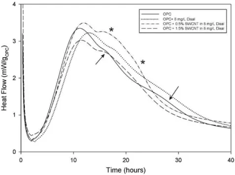
Although the effect of SWCNT/Disal combination was pronounced in C3Ssys-tems, Fig. 5 shows that it was significantly reduced in OPC mixes. In addition, the monotonic progression in effect seen in Fig. 4 was not apparent. Instead, SWCNTs between 0.25 and 1.5% by mass all had approximately the same effect on the time of the OPC’s major C3S hydration reaction. The presence of the
SWCNT also appeared to accelerate and possibly enhance the secondary C3A and
C4AF reactions [Makar and Chan 2008, Pratt and Ghose 1983]. These reactions
are marked by arrows in Fig. 5 for the control samples without SWCNT and by stars for the samples with SWCNT. The heat flow reached a maximum value for both the main C3S reaction and the secondary reactions at 0.5% by mass SWCNT
concentration and fell off with increasing concentration.
Fig. 5 Effect of SWCNT dispersed in Disal on OPC hydration reactions The acceleration of the secondary reactions in the OPC/SWCNT/Disal system was in direct contrast to the results of the previous work using isopropanol disper-sion. There, evidence was provided that the presence of the SWCNT altered the aspect ratio of ettringite formed by very early hydration reactions. No evidence for nucleation of ettringite or other aluminate hydration products was seen and the
secondary reaction peak did not appear to be significantly altered from that of the control sample without sonication.
The results of Fig. 5 in comparison to Fig. 3 and the earlier work [Makar and Chan 2009] suggest that although the Disal was taken up by the SWCNT, with a resulting reduction on the effect of the Disal on C3S hydration, the superplasticizer
was still adsorbed on the C3A surfaces despite the presence of the nanotubes. As a
result, the aluminate reactions were enhanced.
The results in Fig. 3 to 5 have a number of implications for the mechanical per-formance of SWCNT/cement composite materials. As will be discussed in more detail below, the nucleation of C-S-H on SWCNT in sonicated samples appears to produce a high degree of mechanical bonding between the two materials. This bonding would be expected to contribute to the development of classical reinforc-ing behaviour in the composite materials. If the Disal was wrappreinforc-ing the SWCNT, as suggested by Fig. 3 and 4, nucleation of C-S-H on the SWCNT would be inhi-bited, potentially reducing the extent of bonding between the two materials. Mo-rever, if the Disal/SWCNT mixture was preferentially adsorbed on the calcium aluminate surfaces, the results may have been an uneven distribution of SWCNT throughout the matrix. This effect would be expected to be deterimental to the performance of the SWCNT as reinforcement. Not only would areas of minimal reinforcement exist in the matrix, but a sufficiently high concentration of SWCNT in a small number of locations might even act as a crack former in the matrix.
4. Reinforcing Behavior in SWCNT Composites
4.1 Evidence for classical reinforcing behavior
4.1.1 Classical reinforcing behaviour
Non-continuous fibers reinforce matrices by absorbing some of the energy as-sociated with crack formation and propagation. Classical microscope evidence for reinforcing behavior by fibers is generally considered to include three different types of behaviour:
• crack bridging (Fig. 6a), where cracks that would otherwise propagate through a matrix are shown to be crossed by fibers;
• fiber pull-out (Fig. 6b) where larger cracks have caused fibers to leave the matrix; and
• crack deflection (Fig. 6c), where a crack that does not cross the fibers is still deflected around them, rather than propagating in an essentially straight line.
a)
b)
c)
Fig. 6. Schematic Representation of Fiber Reinforcement Mechanisms
Crack bridging and fiber pull out absorb energy as the bond between the fiber and the matrix is broken and the two materials pull away. Crack deflection ab-sorbs energy due to the increased path length of the crack as it goes around the
reinforcements. It is also possible for cracks to be deflected to an extent that they no longer propagate perpendicularly to the direction of loading on the composite material, requiring additional energy to continue the failure process.
4.1.2 Reinforcing Behaviour in SWCNT/OPC composites
All three classical reinforcing mechanisms were observed in SWCNT/OPC composites. Crack bridging was particularly common, being observed in almost all samples hydrated for a day or more. A small section of a particularly striking example of crack bridging can be seen in Fig. 7. Here a crack had propagated in a zig-zag pattern across a 1 mm wide particle of cement paste. Typical widths of the crack were less than 1 µm and additional cracks branched away from it where it changed direction. SWCNT bridged the crack throughout its length and had clearly held the two pieces of the grain together, preventing a complete fracture.
Fig. 7. Crack bridging and fiber pull out (white arrow) in SWCNT/OPC composite (2% SWCNT, 7 days hydration)
An individual example of fiber pull out is also indicated by the arrow in Fig. 7. Fiber pull out was relatively easy to detect during the early stages of hydration [Makar and Chan 2009], but was much less readily observed in sample hydrated for longer periods such as are shown here. It is possible that the lack of observed SWCNT pull outs was due to the adhesion of the pulled out fibers to the matrix along the fracture surface, making observation by SEM difficult. However, other
explanations lie in the distribution of the SWCNT on the surface of the OPC grains and the behaviour of the SWCNT bundles. These points will be discussed further below.
As noted earlier, while almost all incidents of crack bridging were seen in C-S-H, cracking bridging was also seen in a fractured calcium hydroxide crystal (Fig. 2), which was large enough for positive identification by X-ray dispersive spec-troscopy in the SEM. This image was particularly significant as it demonstrates that the ability of SWCNT to nucleate hydration reactions was not limited to the formation of C-S-H alone.
The two different examples of crack bridging also show differences in the con-dition of the SWCNT. In Fig. 7 the nanotube bundles were clearly under tension, with a very linear appearance. In Fig. 2 some of the bundles are also linear, but more appear relaxed, suggesting that the two parts of the Ca(OH)2 crystal had
moved together somewhat after the fracture had taken place.
One feature both images have in common is that the ends of many of the bun-dles branched apart where they were attached to the fracture surfaces. This effect may be due to the way in which the SWCNT bundles were distributed over the surface of the OPC grains. SWCNT bundles distributed by sonication often inter-sect or overlay each other (Fig. 8). The appearance of the SWCNT in Fig. 7 and Fig. 2 suggests that these contacts are not affected by the hydration process.
Crack deflection (Fig. 9, solid arrows) was also seen in the samples, although again less commonly than crack bridging. It was more obvious in those samples with lower quality of dispersion, where the bundles were thicker and more closely located together. The adhesion of the bundles to the surface of the C-S-H is indic-ative of a deflection process. As mentioned earlier, SWCNT have elastic moduli of around 1 TPa and, as a result, tend to stand away from the C-S-H once pulled out of the matrix. The dashed arrow in Fig. 9 indicates an example of such a pulled out bundle.
4.1.3 Comparisons to fracture surfaces in control and other samples
Comparisons between the OPC-SWCNT composite fracture surfaces shown in section 4.1.2 and those created when other hydrated nanomaterial/OPC blends were fractured help to highlight the importance of the SWCNT in modifying the structure of the C-S-H and in creating reinforcing behaviour. A typical fracture surface for a control sample of OPC sonicated alone and then hydrated for 7 days is shown in Fig. 10, while Fig. 11 to 14 show the effects of addition of the nano-alumina, nano-calcium carbonate and nano-titania.
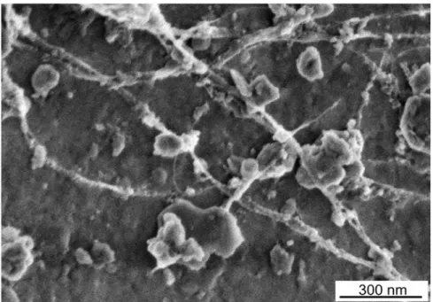
Fig. 8 SWCNT distributed by sonication on OPC surface (1% SWCNT by mass), showing overlaps and intersections of nanotube bundles
Fig. 9. Crack deflection (solid arrows) and fiber pullout (dashed arrow) in SWCNT/OPC composite
Details about the fracture samples and their analysis will be given elsewhere [Makar and Chan, in preparation]. In general, however, the fracture surfaces at 7 days of hydration of OPC sonicated alone showed a mixture of Ca(OH)2 and
C-S-H, with C-S-H predominating. In the case of Fig. 10, a small amount of calcium hydroxide was seen (arrow, identified by morphology), with most of the image taken up by the C-S-H. Other images showed more massive Ca(OH)2 structures.
Some images showed ettringite crystals with aspect ratios of 10 or more, which appear to have formed in pores in the structure. The overall structure appeared to be dense at the scale examined.
Fig. 10 Typical fracture surface for OPC sonicated in isopropanol (7 days hy-dration), showing Ca(OH)2 crystal (arrow)
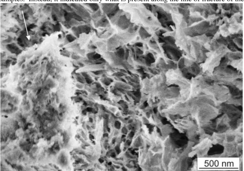
In contrast, the structure of the fracture surfaces of the OPC sonicated with 2% nano-alumina (Fig. 11) after 7 days of hydration appeared to be less dense, with larger pores visible on the surface. The fracture surfaces themselves were rough-er, with a number of images having multiple features similar to that indicated by the arrow in Fig. 11. Both ettringite and Ca(OH)2 were less visible along the frac-ture surfaces.
The images of the fracture surfaces of the OPC sonicated with 2% nanocalcium carbonate (Fig. 12) had a similar density to that for the OPC sonicated alone. However, the overall surfaces were rougher than the OPC sonicated alone and there was a much higher prevalence of ettringite on the fracture surfaces (82% and 21% of the images of samples with and without nanocalcium carbonate,
respec-tively). None of the images from the nanocalcium carbonate samples show frac-tures exposing Ca(OH)2.
Finally, the images of the fracture surfaces from the 7 day hydration samples of OPC sonicated with 2% nano-titania showed either large quantities of Ca(OH)2
(Fig. 13) or relatively dense C-S-H (Fig. 14). The latter surfaces were not dissimi-lar to those seen for hydrated OPC that was sonicated alone. The prevalence of massive Ca(OH)2 was, however, higher than in any of the other samples.
The observed prevalence of the hydration products discussed above should not be taken to represent the actual distribution of C-S-H, Ca(OH)2 or ettringite in the
samples. Instead, it indicated only what is present along the line of fracture of the
Fig. 11 Typical fracture surface for OPC – 2% nano-alumina composite (7 days hydration), showing typical surface texture (arrow)
Fig. 12 Typical fracture surface for OPC – 2% nano calcium carbonate compo-site (7 days hydration) showing ettringite (rods) and C-S-H
Fig. 13 OPC – 2% nano-titania composite fracture surface with massive Ca(OH)2 (7 days hydration)
Fig. 14 OPC – 2% nano-titania composite fracture surface with C-S-H (7 days hydration)
samples. With that condition in mind, an analysis of the images suggests that the individual grains of cement in the samples hydrated in the presence of the nano calcium carbonate and the nano-alumina were less well bonded together than the control sample of OPC hydrated alone and the sample hydrated in the presence of nano-titania. In addition to the differences in structure and surface texture de-scribed above, fracture of the latter two samples produced larger particles, indicat-ing the presence of a tougher matrix.
Despite the differences between the different fracture surfaces described above, all of the four samples had greater similarities to each other than they had to the surfaces of the OPC sonicated with 2% SWCNT samples. As shown in Fig. 7 and 9, the presence of the SWCNT creates a dense matrix with a smoother fracture surface than the other samples. The broken pieces of the matrix were typically much larger than those of the other samples, being in some cases millimeters, ra-ther than micrometers across. Most significantly, no evidence was seen in the other samples of significant cracking such as shown in Fig. 2 and 7. Once cracks had formed in those samples they appear to have propagated through the matrix, causing complete fracture. It was only in the samples containing SWCNT that the crack growth was arrested.
4.2 Evidence for strength of bond
Two types of qualitative evidence were observed in SEM images of SWCNT/OPC composite fracture surfaces. In some cases two pieces of the com-posite material had fractured entirely and remained connected by bridging SWCNT. Subsequently the distance between the pieces of matrix decreased, causing the SWCNT to relax. As a result of the two pieces of the sample moving together, the SWCNT bundles develop curves or bends. SWCNT have elastic moduli of 1 TPa [Salvetat et al. 1999] and a tight bend is therefore indicative of considerable stored energy in the bundle. An equivalent amount of energy would need to be available in the bond between the SWCNT bundle and the matrix in or-der to prevent the bundle from detaching.
Examples of this process can be seen in Fig. 15, where a pair of SWCNT bun-dles are shown in the center of image. Both bunbun-dles were highly curved and it was not obvious which sections of the bundles are continuous with each other. Closer examination suggested the connections shown by the arrows. The two ends of the bundle marked by the solid arrows and the lower end of the bundle marked by the dashed arrows were attached to C-S-H structures that are in the same approximate focal plane as the bundles themselves, suggesting that the tight curvature seen in the former bundle was real and not an artifact of the angle of
Fig. 15. Adhesion of SWCNT ropes to OPC surface (arrows of same type in-dicate continuous SWCNT bundles)
imaging. The bundle marked by the dashed arrows, however, appeared to become narrower as it moves towards its upper contact with the C-S-H, suggesting that its curvature may have been less than would be estimated by direct measurement on the image.
Two other types of bending experienced by SWCNT bundles in cement matric-es are shown in Fig. 16. Here the bundlmatric-es were again bridging a gap between two pieces of C-S-H. These bundles were thicker and had not been as well distributed as those discussed in Makar and Chan [2009] and it was possible that they were present in sufficient concentration to act as a crack former, rather than a rein-forcement. They do, however, clearly illustrate several important points about the interaction between the C-S-H and the SWCNTs.
The appearance of the gap and the SWCNT between the pieces of C-S-H sug-gests that they may have rotated slightly as well as being pulled apart. Bundle 1 in Fig. 16 appeard to be curved or buckled in the middle, while the remaining bun-dles were either straight or pulled completely apart. In addition to the curvature in the bundle 1, all of the bundles showed curvature towards the point of contact with the C-S-H. This effect appeared to be due to each bundle being anchored at a number of places on or in the C-S-H, but held together by van der Wahl’s forces in the centre of the bundle. The bending of the SWCNT bundles also suggests a considerable amount of energy was stored in the bundles, again indicating a strong bonding situation.
The bundles in Fig. 16 also provide another indication of the strength of bond between the SWCNT and the C-S-H. While bundle 1 was curved and bundle 4 was straight and appears to be under some degree of tension, bundles 2, 3 and 5 appear to have been pulled apart at the time of the separation of the C-S-H. In each case corresponding bundle ends, appearing to thin to a lower number of SWCNT, can be seen at the top and bottom of the image. The ends of the sepa-rated bundles did not precisely align with each other, likely due to the bundles def-lecting to minimize their energy once the two parts of the bundle hand separated. Fig. 17 shows a schematic of the separation process.
Individual SWCNT are held in bundles by van der Waal’s forces, which have been estimated as being as high as 11 GPa. While it is impossible to determine from the images the degree to which the individual SWCNT contacted each other, the adhesion of the bundles to the C-S-H when fracture occurs, rather than to other SWCNT, again suggests that the two materials were strongly bonded together.
The apparent degree of bundle to matrix adhesion, as opposed to SWCNT to SWCNT adhesion, was particularly significant when the effect of the size of the bundles was taken into consideration. The strength of bond between the matrix and a SWCNT bundle, as opposed to a single SWCNT, is dependent on the amount of surface contact between the bundles and the matrix. A thicker bundle, with more SWCNT, will have proportionately less contact than a thinner bundle. Bundles of more than 6 SWCNT would be likely to have more SWCNT to SWCNT contact by surface area than SWCNT to matrix. The fact that the SWCNT remained attached to the matrix even when in the form of the relatively thick bundles seen in Fig. 16 also helps to emphasize the strength of the SWCNT/matrix bond.
Fig. 17 Separation of a SWCNT bundle into two due to fracture of C-S-H ma-trix. SWCNT bonded to each side of the fracture (A) slide apart as the crack grows (B), eventually separating entirely (C).
It is worth noting that the branched bundles seen in Fig. 16 may be advanta-geous with respect to bonding and reinforcement. A branched system would be expected to have greater contact with the matrix than a single linear bundle with the same total number of SWCNT. Secondly, the branches mean that the applied forces producing the crack may not necessarily be aligned perpendicularly to the SWCNT in the matrix even if they are aligned perpendicularly to the crack, reduc-ing the effective load applied to the SWCNT and their bond with the matrix.
While examination of the SEM images provides qualitative information on the strength of the C-S-H/SWCNT bond, direct measurement of the strength of bond between a matrix material and SWCNT is a difficult undertaking. Examples in the literature have relied on attaching one end of an individual nanotube to an AFM probe or other structure and immersing it in unhardened matrix material [ref]. This method can work well when bonds are expected to be weak, but in the case of a well bonded material the results may be affected by changes in the attachment between the sample support structure and the SWCNT as well as the matrix.
Another approach would be to calculate the apparent strength of the bond based on SWCNT or SWCNT bundle deflections. This method uses the known 1 TPa value of the elastic modulus of the SWCNT [Salvetat et al. 1999] and the esti-mated curvature of bent SWCNT to estimate the energy associated with the inte-raction between the matrix and the nanotubes. In principle, this calculation could produce quantitative results for bond energy, but there several issues limit its utili-ty. First, determination of degree of curvature is limited by the quality and nature of the images involved. This issue has been discussed above with respect to Fig. 15. Secondly, precise estimates of the number of SWCNT in a bundle can not be obtained from this form of SEM imaging. Finally, it is impossible to determine the extent to which the SWCNT bundles penetrate the surface of the C-S-H. As a result, there is no way to determine the precise length of SWCNT bonded to the C-S-H. In the case of the sliding behaviour shown in Fig. 16, the second and third limitations also apply. In particular, it is certainly possible that there are more SWCNT attached to C-S-H than were present in the center of the bundle.
Given these limitations the best estimate that can be made of the bond strength is that it is likely within an order of magnitude of the van der Waals forces holding the SWCNT bundles together. This estimate arises directly from the behaviour shown in Fig. 16 and 17, where the ends of the bundle remain attached to the ma-trix, rather than one end completely detaching from the matrix. This estimate in turn suggests that the bonding between the matrix and the SWCNT bundles may itself arise from van der Waals forces. If this is indeed the case, the C-S-H im-mediately around the SWCNT may be significantly more ordered than the bulk material. Further work, particularly using high resolution transmission electron microscopy, is needed to investigate this possibility.
4.3 Implications of methods of dispersion for composite performance
The apparent high degree of bonding between the SWCNT bundles and the ma-trix suggests a corresponding degree of reinforcing capability. Fully taking advan-tage of that capability requires dispersing the SWCNT as evenly as possible throughout the C-S-H matrix. The cement hydration process, where outer product grows outward from the surface of the grain and inner product forms underneath it limits the locations where reinforcement can take place. Reinforcement is likely to be limited to the outer product unless the reinforcing material can remain in so-lution and is sufficiently small that it can be carried into the inner product zone be-fore diffusion of ions through the existing hydration products becomes the predo-minant hydration mechanism [Taylor, 1997].Neither of the two methods of dispersing SWCNT discussed here is likely to provide a means of reinforcing the inner product. Depositing the SWCNT on the grain surface accelerates the onset of the hydration reactions and provides loca-lized reinforcing behaviour, but once the hydration products have covered them, any remaining product that forms between the cement grains will not be directly reinforced. Similarly, dispersing SWCNT or nanoparticles in superplasticizer ap-pears to be likely to cause concentrations of the nanomaterial on or near C3A in
the unhydrated OPC. The remainder of the OPC is likely to experience a reduced degree of reinforcement, with bonding potentially hampered by the superplasticiz-er itself.
It is certainly possible that other methods of dispersion of carbon nanotubes and/or other nanomaterials could be developed to position them so that they would stand perpendicularly away from the surface (in the case of nanotubes or nano-rods) or remain suspended in the hydration water. Such processes would still leave the inner product region unreinforced, but would improve the extent of outer product reinforcement.
5. Conclusions
At the microscopic level, SWCNT/OPC composites showed evidence of clas-sical reinforcing behaviour in the form crack bridging, fiber pullout and crack def-lection. This reinforcing behaviour occured even when the SWCNT were present in the form of bundles, rather than individual nanotubes. The high degree of adhe-sion between SWCNT in a bundle means that separation of a bundle during crack formation acts as a fourth form of reinforcing mechanism, with energy being ab-sorbed as the van der Waal’s forces holding the bundle together are overcome.
The ability of the hydrated OPC matrix to remain attached to the ends of the SWCNT bundles during crack growth suggested that a high degree of bonding ex-isted between the two materials. A qualitative estimate of the strength of bond is
that it was within an order of magnitude of the van der Waals forces in the bundle, but no numerical estimate was possible with the data examined here. The high strength of bond appeared to be due to the nucleation of the C-S-H by the SWCNTs and its formation along the SWCNT bundles. Comparisons between the peformance of the SWCNT as a nucleating agent and that of other nano-materials, as well as the preferential nucleation of C-S-H instead of Ca(OH)2 on the
SWCNT, suggested that the predominant nucleation mechanism was electrostatic in nature, rather than adsorption of metallic ions.
Dispersion remains a challenge in the use of SWCNT in cement systems. While SWCNT can be successfully dispersed in Disal, the hydration behaviour of those systems suggests that the SWCNT were being wrapped by the admixture, which appeared to inhibit the nucleation behaviour produced by SWCNT dis-persed by sonication. In addition, the presence of the admixture appeared to cause the SWCNT to nucleate C3A and C4AF reaction products, in addition to C-S-H.
Further work is needed on dispersion issues to reach the full potential of SWCNT as a reinforcing material.
Despite the need for improved dispersion techniques, SWCNT remain extreme-ly promising as nanometric reinforcing materials. As with other nanomaterials, the real challenges to use in the field are not the development of the material. In-stead, they involve the safe and appropriate use of the material in construction. Scaling laboratory procedures to industrial production, producing the material in an manner safe for construction construction workers (i.e. without release of na-nomaterials in the cement or ready mix plant), and following appropriate envi-ronmental and health guidelines through the product’s life cycle from placement to demolition all present significant, long term challenges that need to be over-come.
Acknowledgements
Sonicated OPC samples and those made with nano-alumina, nano-calcium car-bonate and nano-titania were prepared and imaged by Gordon W. Chan. The sample shown in Fig. 8 was also prepared and imaged by Gordon W. Chan. The remaining SWCNT samples shown in Section 4 were prepared by Jeanne Luh. Kaela Essegehaier prepared the SWCNT samples for isothermal conduction calo-rimetry in section 3.
Reference
Ausman KD, Piner R, Lourie O, Ruoff RS, Korobov M (2000) Organic Solvent Dispersions of Single-Walled Carbon Nanotubes: Toward Solutions of Pristine Nanotubes. J. Phys. Chem. B 104(38): 8911 -8915.
Campillo I, Dolado JS, Porro A (2004) High performance nanostructured materi-als for construction. In: Bartos PJM, Hughes JJ, Trtik P, Zhu W(eds.) Nanotech-nology in Construction (Proceedings of the First International Symposium on Nanotechnology and Construction, 23rd-25th June, 2003, Paisley, Scotland), Roy. Soc. Chem., London: 215-226.
Chiang IW, Brinson BE, Huang AY, Willis PA, Bronikowski MJ, Margrave JL, Smalley RE, Hauge RH, (2001) Purification and characterization of single-wall carbon nanotubes (SWNTs) obtained from the gas-phase decomposition of CO (HiPco process). J. Phys. Chem. B. 105(35): 8297-8301.
Cwirzen A, Habermehl-Cwirzen K, Penttala V (2008) Surface decoration of car-bon nanotubes and mechanical properties of cement/carcar-bon nanotube composites. Ad. Cem. Res. 20: 65-73.
De Ibarra YS, Gaitero JJ, Campillo I (2006) Atomic force microscopy and nanoindentation of cement pastes with nanotube dispersions. phys. stat. sol. (a) 203: 1076-1081.
Kingston CT, Homenick CM, Guan J, Simard B (in preparation) Nondestructive purification of single-walled carbon nanotubes using simple solvents.
Kingston CT, Jakubek ZJ, Denommee S, Simard B (2004) Efficient laser synthesis of single-walled carbon nanotubes through laser heating of the condensing vapori-zation plume. Carbon, 42: 1657-1663.
Konsta-Gdoutos MS, Metaxa ZS, Shah SP (2010) Highly dispersed carbon nano-tube reinforced cement based materials. Cem. Conc. Res. 40 (7): 1052-1059. Li GY, Wang PM, Zhao X (2005) Mechanical behaviour and microstructure of cement composites incorporating surface-treated multi-walled carbon nanotubes. Carbon 43: 1239-1245.
Li GY, Wang PM, Zhao X (2007) Pressure-sensitive properties and microstruc-tures of carbon nanotube reinforced cement composites. Cem. Conc. Comp. 29: 377-382.
Makar JM (2009) Carbon Nanotube / Cement Composite Materials. In: Somani PR and Umeno M (eds.) Carbon Nanotubes: Multifunctional Materials, Applied Science Innovations Pvt. Ltd, Pune, Maharashtra, India
Makar JM, Chan GW (2008) End of the induction period in ordinary Portland ce-ment as examined by high resolution scanning electron microscopy. J. Amer. Ce-ram. Soc. 91: 1292-1299.
Makar JM, Chan GW (2009) Growth of cement hydration products on single walled carbon nanotubes. J. Am. Ceram. Soc. 92: 1303–1310.
Makar JM, Chan GW (in preparation) Effects of nanoparticles and ultrahigh sur-face area materials on growth of cement hydration products.
Makar JM, Chan GW, Esseghaier KY (2007) An Additional Hydration Reaction at the End of the Cement Induction Period. J. Mater. Sci. 42: 1388-1392.
Makar JM, Margeson J and Luh J (2005) Carbon nanotube/cement composites – early results and potential applications. In: Banthia N, Uomoto T, Bentur A, Shah SP (eds.) Construction Materials (Proceedings of ConMat ’05 and Mindess Sym-posium, Vancouver, Canada, August 22-24, 2005), UBC Press, Vancouver, Can-ada: 32.
Narimatsu K, Niidome Y, Nakashima N (2006) Pulsed-laser induced flocculation of carbon nanotubes solubilized by an anthracene-carrying polymer. Chem. Phys. Lett. 429(4-6):488-491.
Raki L, Beaudoin J, Alizadeh R, Makar J, Sato T (2010) Cement and Concrete Nanoscience and Nanotechnology. Materials 3: 918-942.
Pratt L, Ghose A (1983) Electron microscope studies of Portland cement micro-structures during setting and hardening. Phil. Trans. R. Soc. Lond. A 310: 93-103. Salvetat J-P, Bonard J-M, Thomson NH, Kulik AJ, Forró L, Benoit, W. Zuppiroli L (1999) Mechanical Properties of Carbon Nanotubes. Appl. Phys. A 69: 255-260. Sato T, Beaudoin JJB (in submission) Effect of Nano-CaCO3 on Hydration of
Cement Containing Supplementary Cementitious Materials, Adv. Cem. Res. Sato T, Beaudoin JJB (2006) The Effect of nano-sized CaCO3 addition on the hy-dration of OPC containing high volumes of ground granulated blast-furnace slag. In: 2nd International RILEM Symposium on Advances in Concrete Through Science and Engineering (Québec City 2006-09-11), 355-366.
Strano M.S. (2006) Polymer-wrapped nanotubes. Nat. Matr. 5(6): 433-434. Taylor HFW (1997) Cement Chemistry 2nd Ed., Thomas Telford, London
Vodenitcharova T, Mylvaganam K, Zhang LC (2007) Mechanical interaction be-tween single-walled carbon nanotubes during the formation of a bundle. J. Matr. Sci. 42(13): 4935-4941.
Walters DA, Ericson LM, Casavant MJ, Liu J, Colbert DT, Smith KA, Smalley RE (1999) Elastic strain of freely suspended single-wall carbon nanotube ropes. App. Phys. Let. 74: 3803-3805.
Wansom S, Kidner NJ, Woo LY, Mason TO (2006) A.C.-impedance response of multi-walled carbon nanotube/cement composites. Cem. Conc. Comp. 28: 509-519.
Xiang XJ, Torwald TL, Staedler T, Trettin RHF (2005) Carbon nanotubes as a new reinforcement material for modern cement-based binders. In: NICOM2 (Pro-ceedings of the Second International Symposium on Nanotechnology and Con-struction, 13th-16th November 2005, Bilbao, Spain): 209-213.
Yu M-F, Lourie O, Dyer MJ, Moloni K, Kelly TF, Ruoff RS (2000), Strength and Breaking Mechanism of Multiwalled Carbon Nanotubes Under Tensile Load. Science 287: 637-640.
Zhan G-D, Kuntz JD, Wan J, Mukherjee AK (2002) Single-wall carbon nanotubes as attractive toughening agents in alumina-based nanocomposites. Nat. Mater. 2: 38-42.
Zheng LX, O'Connell MJ, Doorn SK, Liao XZ, Zhao YH, Akhadov EA, Hoff-bauer MA, Roop BJ, Jia QX, Dye RC, Peterson DE, Huang SM, Liu J & Zhu YT (2004) Ultralong single-wall carbon nanotubes. Nat. Matr. 3: 673-676.