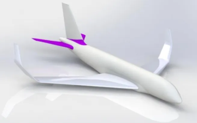
Aerodynamic Optimization of a Morphing Winglet Design
Texte intégral
Figure

Documents relatifs
Les stations services (lavage, graissage) sont génératrices éga- lement de pollution ; leurs eaux usées chargées en matières organiques déver- sées telles quelles dans les réseaux
Best-fit persistent phase continuum and broad Fe emission line model (red) of Table 1 modified by two photoionized absorption lines (see Section 2.1.3 ) overplotted on the
This framework captures four crucial determinants of the interplay between the energy sector, sustainability objectives, and globalization processes: (a) non marginal deviations
This overprotection of seats not only causes the nested deterministic approaches to perform better than the nested probabilistic approaches, but it can cause the
Various development and rehabilitation projects for smallholder tree crops have been established, which were mainly, are grouped into two schemes: Perusahaan Inti
د ـ ﺪﻤﳊﺍ ﺸﻟﺍ ﻝﻮﺻﺃ ﻪﻠﻳﱰﺗ ﻥﺎﻫﱪﺑ ﺢﺿﻭﺃ ﻱﺬﻟﺍ ﷲ ﻪﻛﻮﻠﺳ ﺝﺎﻬﻨﻣ ﻦﻋ ﻒﺸﻛﻭ ،ﲔﺘﳌﺍ ﻉﺮ ﻪﻓﺭﺎﻌﻣ ﺭﺎﲝ ﰲ ﺍﻮﺻﺎﻏﻭ ﺔﳛﺮﳌﺍ ﻪﺿﺎﻳﺭ ﰲ ﻢﻫﺭﺎﻈﻧﺃ ﻖﻴﻗﺪﺑ ﺍﻮﺣﺮﺴﻓ ،ﻦﻳﺪﻬﺘﺍ ﺔﻤﺋﻷﺍ
The aggregated level of abatement is a usually chosen such that the marginal cost and benefit are both equal to the marginal damage of pollution and the aggregated level
We successfully developed a general air-side feed stream con- tamination model, which has been validated with experimental data on fuel cell toluene contamination at four
