Science Arts & Métiers (SAM)
is an open access repository that collects the work of Arts et Métiers Institute of
Technology researchers and makes it freely available over the web where possible.
This is an author-deposited version published in: https://sam.ensam.eu Handle ID: .http://hdl.handle.net/10985/19688
To cite this version :
Mamoun FELLAH, Linda AISSANI, Mohammed ABDUL SAMAD, Alain IOST, Touhami MOHAMED ZINE, Alex MONTAGNE, Corinne NOUVEAU - Effect of Replacing Vanadium by Niobium and Iron on the Tribological Behavior of HIPed Titanium Alloys - Acta Metallurgica Sinica (English Letters) - Vol. 30, n°11, p.1089-1099 - 2017
Any correspondence concerning this service should be sent to the repository Administrator : archiveouverte@ensam.eu
Effect of Replacing Vanadium by Niobium and Iron
on the Tribological Behavior of HIPed Titanium Alloys
Mamoun Fellah1,2•Linda Aissani2,3•Mohammed Abdul Samad4•Alain Iost5•Touhami Mohamed Zine2•
Alex Montagne5•Corinne Nouveau6
Abstract This study aims to examine the effect of replacing vanadium by niobium and iron on the tribological behavior of hot-isostatic-pressed titanium alloy (Ti–6Al–4V) biomaterial, using a ball-on-disk-type oscillating tribometer, under wet conditions using physiological solution in accordance with the ISO7148 standards. The tests were carried out under a normal load of 6 N, with an AISI 52100 grade steel ball as a counter face. The morphological changes and structural evolution of the nanoparticle powders using different milling times (2, 6, 12 and 18 h) were studied. The morphological characterization indicated that the particle and crystallite size continuously decrease with increasing milling time to reach the lowest value of 4 nm at 18-h milling. The friction coefficient and wear rate were lower in the samples milled at 18 h (0.226, 0.297 and 0.423; and 0.66 9 10-2, 0.87 9 10-2and 1.51 9 10-2lm3N-1lm-1) for Ti–6Al–4Fe, Ti–6Al–7Nb and Ti–6Al–4V, respectively. This improvement in friction and wear resistance is attributed to the grain refinement at 18-h milling. The Ti–6Al–4Fe samples showed good tribological performance for all milling times.
KEY WORDS: Tribological behavior; Titanium alloys; Wear testing; Nanotribology; Milling time; Hot isostatic pressing (HIPing)
1 Introduction
Usage of titanium alloys is continuously increasing in biomedical applications due to their high biocompatibility and good mechanical properties compared to conventional biomaterials [1–7]. Due to their excellent properties, they have also been applied to aerospace industry, petroleum industry and also in medicine [8–10]. It is known that Ti can be alloyed with variety of elements to further improve its properties, such as high-temperature performance and formability [1,11,12]. The strength of the alloy is much increased over that of pure titanium, when aluminum (Al) and vanadium (V) are added to pure titanium in small quantities [13].
However, the release of Al and V ions from the disso-lution of the passive film on the alloy surfaces produces a toxic effect, causing severe health problems [14, 15]. For this reason, the non-allergic and non-toxic beta-eutectic (b) elements such as niobium (Nb) and iron (Fe) have been Available online athttp://link.springer.com/journal/40195.
& Mamoun Fellah mamoun.fellah@yahoo.fr
1 Mechanical Engineering Department, ABBES Laghrour
University, P.O. 1252, 40004 Khenchela, Algeria
2 Tribology, Materials Surface and Interfaces Group,
Laboratory of Foundry, BADJI Mokhtar University, BO 12, CP 23000 Annaba, Algeria
3 Physics Department, ABBES Laghrour University, P.O.
1252, 40004 Khenchela, Algeria
4 Mechanical Engineering Department, KFUPM, Box 1180,
Dhahran 31261, Kingdom of Saudi Arabia
5 Laboratory of Mechanics Surfaces and Processing Materials,
ARTS ET METIERS ParisTech, Boulevard Louis XIV 8, 59046 Lille Cedex, France
6 La.Bo.Ma.P, ENSAM, Rue Porte de Paris, 71250 Cluny,
used as safe alloying elements for developing low elastic modulus and high-strength titanium alloys [16,17]. The Ti alloy with aluminum and iron is found to be more suit-able for implant applications [17].
Ti is currently used in dentistry, and the Ti–6Al–4V alloy is used in many orthopedic applications. However, it is a subject of many disadvantages and limitations [18,19]. The most important obstacles to hinder the wider use of titanium-based alloys and limit their applications under sliding conditions and contact loads [20–22] are poor tri-bological properties such as high friction coefficient and low abrasive wear resistance coupled with relatively low hardness [23]. Therefore, in order to improve the tribo-logical properties of titanium alloys, various methods have been applied for improving resistance to abrasive wear [24] and plastic shearing [25]. Moreover, tribological properties may also be improved or modified by surface coatings, changing microstructure of surface layers or thermochem-ical treatments [25–28]. Johnson and Eberhardt [29], for example, improved the wear resistance of Ti–6Al–4V using thermal oxidation. Although this is a low-cost pro-cessing route for wear performance enhancement, it suffers limitations as other processes such as nitriding and borid-ing [24,30,31].
Recently, a new processing route for the commercial production of a lower grade of titanium alloys has been developed [21], which should facilitate the usage of Ti, particularly in medical industry. However, up to now, lot of efforts have only been dedicated to evaluate the mechanical and microstructural properties of b titanium alloys with Fe and Nb addition, but very few studies have been system-atically conducted to evaluate the tribological behavior and mechanical properties of a-type Ti–6Al alloy with Fe and Nb addition [32].
Nanostructured titanium alloys have also been devel-oped to improve the mechanical properties [33–38]. However, correlations among conditions of milling, microstructure and tribological behavior have not been very well studied for these nanostructured alloys [39–41]. In mechanical milling, one of the most important param-eters is the milling time, as it significantly affects the wear resistance and durability of total hip prosthesis [42–44]. Usually, the time is chosen so as to achieve a steady state between the fracturing and cold welding of the particles. The required time varies depending on the milling condi-tions. Therefore, it is always good to mill powders just for the necessary time and no more [45].
Therefore, the present study was undertaken with the main focus of examining the effects of replacing vanadium (V) by niobium (Nb) and iron (Fe) on the tribological behavior of nanostructured milled and hot-isostatic-pressed (HIPed) titanium alloys. In addition, the correlation between the milling time, hardness, microstructure, lattice
parameters and wear resistance will also be evaluated, and the possibility of using nanostructured Ti–6Al–4Fe and Ti– 6Al–7Nb alloys as biomaterial alloys will be discussed.
2 Materials and Methods
2.1 Synthesis Process
Ti, Al, Nb, Fe and V powders with 99.94% purity and 10–50 lm average particle sizes are used. The powders were milled at 2, 6, 12 and 18 h, respectively, using a high-energy ball mill, Fritsch P7, under an argon atmosphere. The milling media consisted of 18-mm-diameter alumina balls confined in a 350-ml volume vial. The weight ratio of ball to powder was about 20. The milling was carried out in cycles of 28 min with a pause of 9 min in between the cycles. The vials were opened after a 35- to 40-min cooling period, after each milling operation.
The milled powders of Ti–6Al–7Nb (6 wt% Al, 7 wt% Nb and the rest Ti), Ti–6Al–4Fe (6 wt% Al, 4 wt% Fe and the rest Ti) and Ti–6Al–4V (6 wt% Al, 4 wt% V and the rest Ti) were pressed uniaxially at 100 MPa into 15-mm-diameter circular disks with a thickness of 5 mm by a rigid steel die followed by sintering in a high vacuum furnace at 3 9 10-5 mbar at temperatures of 1150°C for 1 h at a heating rate of 20 K min-1to obtain a closed porosity [46]. In order to produce a high-density nanocrystalline material (density of 99% measured using the Archimedes principle), the sintered samples subsequently were hot isostatically pressed (HIPed) using ASEA-HIP at 1050 °C at a heating rate of 20 K min-1and at an isostatic pressure of 300 MPa for 30 min [47–49].
2.2 Microstructure Characterization
For microstructure characterization, the samples were polished with 2-nm diamond paste. After preparing the surfaces, samples were etched with Kroll’s reagent (10HNO3–2HF–88H2O) and characterized by scanning
electron microscopy (SEM, JEOL JSM-3C) to examine morphology and particle sizes. Transmission electron microscopy was used to observe and measure the average grain size of the starting powder morphology. The phase identification and structural evolution were examined using X-ray diffractometry with CuKa radiation. Also, the grain size in the samples was evaluated using Williamson–Hall formula equation [50].
The Vickers hardness of the nanostructured titanium alloys was evaluated using a universal hardness testing machine (Zwik ZHV 2.5) with a Vickers diamond indenter for which elastic constant Ei= 1140 GPa and Poisson ratio
2.3 Tribological Characterization
A ball-on-disk-type oscillating tribometer (TRIBOtester) was used for tribological tests, under wet conditions using physiological solution in accordance with the ISO7148 standard. The tests were carried out under a normal load of 6 N, with an AISI 52100 grade steel ball (E = 210 GPa, HV0.05= 840 and density of 7.85 g/cm3) as a counter face.
The HIPed disk specimens of 15 mm in diameter and 5 mm in thickness polished to 0.50–0.70 nm surface roughness were used for the tests. Before each test, the balls and the samples were ultrasonically rinsed in acetone. After the wear tests, the worn surface morphology was observed by SEM. Tested samples and the counter face balls were weighed before and after the tests, but a modest weight difference was observed.
3 Results and Discussion
3.1 Microstructural Characterization
3.1.1 Grain Size and Distribution
Morphology and particle size evolution of milled titanium alloy powders as a function of milling time are shown in Fig.1. It is known that the process of milling consists of three main stages: (I) cold welding, (II) fracturing and (III) steady-state condition [51, 52]. At the first milling stage (2 h), the powder particles are found to be angular and irregularly shaped with a 4- to 30-lm size distribution and were dispersed uniformly throughout the surface. It is observed that the grain size is relatively small as well. It is clear that at 2-h milling, the particles were fine and had formed some agglomerates with 80 vol% of particle size less than 30 lm and 20 vol% with size less than 10 lm. It is known that during the milling process, the milling energy deforms the powders which are compressed by the process of microforging [53]. As shown in Fig.1, irregular and elongated grains with pointed ends were observed. At 2-, 6- and 12-h milling, an increase in the quantity of the fine grains was observed.
However, for 18-h milled samples, agglomerates/cluster of particles appeared. It is observed that with an increase in milling time, the particle size decreased due to the exces-sive fracturing of particles as compared to that of the cold-welding process. Moreover, with increasing milling time, the chip morphology changed to equiaxed morphology [51,52]. Compared to early milling stages (2 h), the par-ticles size was more uniform after 18-h milling.
With the increase in milling time, the particles are deformed by the higher milling energy and they get com-pressed shapes and the particles size reduces to 2–5 lm,
due to the fracturing of the powder before the cold-welding stage. It is observed that at 18-h milling time, the milled particles consist of 60 vol% with size \ 60 nm and 40 vol% with size \ 8 nm. However, while the particles with sizes less than 60 nm could be clearly seen, the particles with the sizes less than 8 nm are not seen as they may have agglomerated.
3.1.2 Particles Powder Morphology
At different milling times, the X-ray diffraction patterns (Fig.2) of milled titanium alloy powders show the exis-tence of (a ? b) phases only. The diffractograms corre-sponding to the lattice planes for a-hcp (100), (002), (101), (102), (110), (101), (112), (004), (104) and for b-bcc (100), (110), (004), (220) are indicated. As observed in the patterns, the maximum peak positions of all titanium alloy powders as a function of milling time are similar but their width progressively increases with increasing milling time and their intensity decreases in consequence of the crystallite size refinement [54].
After 18-h milling, the peaks corresponding to (100), (110), (004) and (220) disappeared. This can be due to the gradual diffusion of Al, V, Fe and Nb atoms into the Ti structure, since they have enough solid-state solubility in Ti in contrast to zero solubility of Ti in Al, Fe, Nb and V [55]. Previous investigations have also concluded the diffu-sion of Al atoms in Ti lattice structure as the cause for the disappearance of the Al diffraction peaks after 4-h milling [56]. Trends of Ti peak shift are specifically indicated for the Ti (101) peak at 2-h milling (Fig. 2). This shift may have been caused by one element solution in Ti. The shift in Ti peaks toward lower angles occurs due to the diffusion of Al (rAl= 1.82 A˚ ), V (rV= 1.43 A˚ ), Nb (rNb= 1.43 A˚ )
and Fe (rFe= 1.26 A˚ ) atoms in the Ti (rTi= 2 A˚ )
inter-stitial spaces. By the end of this shift, a-Ti (002) and a-Ti (103) diffraction peaks are replaced with Ti (110) and b-Ti (211) peaks; subsequently, the stabilization of b-b-Ti phase in the primary a-Ti matrix is consequently guaran-teed. The new b-Ti phase lattice parameter is identical to the literature values and corresponds to the bcc structure with about ab= 3.3 A˚ . Peak expansions can be indication
of fine crystallite size and increased lattice strains [57]. Nevertheless, chemical heterogeneities and/or stress gra-dients can also cause peak expansion [57].
To evaluate the effects of Al, Fe, Nb and V atom dis-solution on the Ti peak shift, pure titanium’s (101) peak position at different milling times was also investigated, and no shifts were observed. In the present research, solid-state solubilities of Al, Fe, Nb and V could therefore be the only cause for the shift of Ti peaks. Thus, after 18-h mil-ling, the solid-state in situ synthesis of nanostructured Ti– 6Al–4Fe, Ti–6Al–7Nb and Ti–6Al–4V alloys with
nanostructured grain size of about 21.21, 29.10 and 30.11 nm, respectively, was obtained.
The evolution of crystallite size {D} of milled (a ? b) titanium alloy systems versus milling time is shown in
Fig.3. It is expected that with increasing milling time, the grain size was decreased reaching a lowest critical value, as the mechanical milling is the result of the competition between the breaking procedures and cold fusions of components that cause the activation and particle refine. At the steady point, the breaking and fusion speed will be balanced [58,59].
As shown in Fig.3, the crystallite size decreased slowly with milling time. The same dependency on milling time of lattice parameters and crystallite size was decrypted by others [60]. Mixed powder crystallite sizes at 2 h are 50.02, 54.10 and 56.20 nm, which then decreases to 24.12, 31.19 and 33.03 nm after 12 h reaching the values of 21.21, 29.10 and 30.11 nm after 18 h for Ti–6Al–4Fe, Ti–6Al– 7Nb and Ti–6Al–4V, respectively.
These results are attributed to the grain size refinement, followed by an increase in the internal strains. The a and b phase lattice parameters were determined from the 2h positions of their particular diffraction peaks. The lattice parameter, a, for the b phase was determined from the bcc peaks (100), and the lattice parameter, a, for the a phase was determined from the hcp peaks (110), assuming that the c/a ratio is equal to 1.5963, which corresponds to the value in the base metal at room temperature. These two peaks represent the strongest diffraction peaks for each phase and provided good measurements throughout the entire milling time of the lattice parameter for each tita-nium powder.
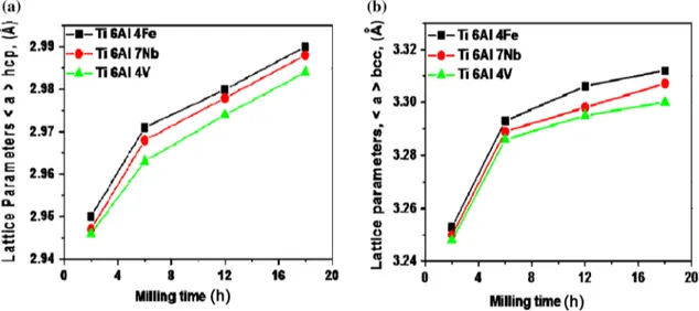
A significant lattice parameter increase is clearly observed in Fig.4 after 2-h milling. Nevertheless, at 18 h only the (a ? b) phases exist. As clearly observed in Fig.4, with increasing milling time from 2 to 18 h milling, the lattice parameters (ab, aa& ca) increase.
The, ab, lattice parameter increases with increasing
milling time (3.253–3.312 A˚ ), (3.250–3.307 A˚) and (3.248–3.300 A˚ ), which represents 1.18%, 1.75% and 1.16% of cell volume expansion for Ti–6Al–4Fe, Ti–6Al– 7Nb and Ti–6Al–4V, respectively. The lattice parameter, aa, also increases with increasing milling time
(2.950–2.990 A˚ ), (2.950–2.988 A˚) and (2.946–2.984 A˚), representing approximately a cell volume expansion of 1.35%, 1.28% and 1.27% for Ti–6Al–4Fe, Ti–6Al–7Nb and Ti–6Al–4V, respectively.
Moreover, the lattice parameter, ca, increases with
increase in the milling time, assuming that the c/a ratio is equal to 1.5963, which is interpreted by the peaks shift to smaller angles 2h [61]. Usually, the cell parameters increase with the increasing milling time for the most part due to: (I) pound formation by mechanical milling and (II) the introduction of first-order constraints [62].
Fig. 2 XRD patterns of milled titanium powders alloys versus: a 2-h and b 18-h milling
Fig. 3 Average crystallite sizeshDi (nm) of titanium powder alloy mixtures versus milling time
3.1.3 Microhardness
The HV0.05Vickers microhardness tests of milled titanium
alloys after 2-, 6-, 12- and 18-h milling are shown in Fig.5. As presented, with increasing milling time the microhard-ness increased. The highest values of 660, 588 and 535 HV0.05were obtained after 18 h and the lowest values of
335, 320 and 304 HV0.05were obtained after 2-h milling
time, for Ti–6Al–4Fe, Ti–6Al–7Nb and Ti–6Al–4V, respectively. It is important to point out that the crystallite size reduction may have contributed to the increase in hardness of the titanium alloys, due to the strengthening mechanism by grain refinement.
3.2 Tribological Characterization
3.2.1 Friction Coefficient Evolution
The friction coefficients evolutions of nanostructured tita-nium alloys milled for different times (2, 6, 12 and 18 h), at applied load of 6 N, and a sliding velocity of 15 mm s-1, are registered and displayed in Fig.6. As observed in Fig.6, the Ti–6Al–4Fe, Ti–6Al–7Nb and Ti–6Al–4V alloys exhibit similar frictional behavior under the present experimental conditions. The coefficient of friction increases quickly through the first few meters and then decreases. After this stage, the variations become lesser and the coefficient of friction continuously increases slightly throughout the test end.
At an advanced stage, tracks are smoothened out and the coefficient of friction reaches a steady state. At 2-h milling, the specimens exhibit more fluctuations, which can be attributed to the higher roughness of specimens. In addition to this, with increasing surface hardness as a function of milling time, the real contact area decreases; therefore, the friction coefficient decreases. It is clear from Fig. 6that the coefficient of friction showed a decreasing trend as a function of milling time, and it was lesser for Ti–6Al–4Fe samples for all the milling times. At 18-h milling, all samples showed the lowest and the highest coefficient of friction at 2 h.
As shown in Fig.7, the average mean values of the friction coefficient are in the range of 0.402–0.226 for Ti– 6Al–4Fe, while it varies between 0.542 and 0.297 for Ti– 6Al–7Nb, and 0.586 and 0.423 for Ti–6Al–4V as a func-tion of milling time from 2 to 18 h, respectively. It is clearly observed that the coefficient of friction decreases with increasing milling time, which can be attributed to the Fig. 4 Lattice parameters (A˚ ) a and c for hcp and a for bcc versus milling time for titanium powder alloys
enhancement in the mechanical proprieties by grain refinement.
3.2.2 Evolution of Volume and Wear Rate
As shown in Fig.8, the wear rate of HIPed titanium alloys tends to decrease with increasing milling time from 2 to 18 h. It varied within the range of 1.34 9 10-2–0.66 9 10-2, 1.44 9 10-2–0.87 9 10-2 and 1.92 9 10-2–1.51 9 10-2 lm3N-1lm-1for Ti–6Al–4Fe, Ti–6Al–7Nb and Ti–6Al– 4V, respectively. It seems that the milling time has a
significant influence on the wear volume and wears rate of HIPed titanium alloys. All the estimations made range from 10-1to 10-2(lm3N-1lm-1).
The above results confirm that the tribological behavior of titanium alloys not only depends on the milling time, but also depends on their chemical composition. As depicted in Figs. 7and8, the samples milled for 18 h display a good wear resistance and tribological behavior. This behavior of titanium alloys (especially those alloyed with Fe) milled at 18 h can be attributed to the grain size refinement and enhanced mechanical properties. After 3100 m of sliding, the surface morphology was examined by SEM to evaluate the wear mechanisms.
As can be seen, both the friction coefficient and the wear rates are observed to decrease with increasing milling time (Figs. 7and8). This may be attributed to the better com-paction of the transfer layer because of the increased fric-tional heat. At the same time, the extent of coverage of the transfer layer also increases, which results in lowering of the friction and wear rate. The results of wear rate could also be explained on the basis of the hardness of the milled samples and strengthening mechanisms, since the hardness of the samples milled for 2 and 6 h is less, and hence, they show a relatively higher rate of wear in comparison with other milling time of 12 and 18 h.
Figure9 shows the worn surface morphologies of typi-cal as-received titanium alloys and titanium alloys prepared after milling for 18 h. A moderate wear track was observed from the SEM micrograph samples. Moreover, wear debris particles with small sizes are also observed, which almost certainly were detached by plastic deformation. The enhancement in wear resistance of the 18-h milled titanium alloys may be attributed to its high hardness values. A Fig. 6 Friction coefficients of milled titanium alloys versus sliding
distance
Fig. 7 Mean friction coefficients of titanium alloys under different milling times
significant damage of surface with deformed and smeared appearance was observed in all tested samples.
A significant wear debris which is build up on the inside and the external periphery (Fig.9) of the wear track was observed. In most cases of titanium alloys, it was observed that the weight loss was caused by adhesive wear and lamination defect.
As shown in Fig.9, the extensive grooves in the case of as-received and HIPed samples can be seen (Fig.9a), suggesting an abrasive wear mechanism. In the case of 18-h milled titanium-based alloys, the adhesive wear mechanism and lamination defect were observed (Fig.9b). The extensive formation of slip bands possibly leads to the observed cracking in all the investigated materials.
In case of Ti–6Al–4Fe, the abrasion severity is much less compared to the investigated Ti–6Al–4V and Ti–6Al–6Nb alloys. Moreover, the smooth appearance of the worn surface correlates well with the low friction coefficient obtained with this material. It can be observed that in all wear tracks (Fig.9), both adhesive and abrasive wear mechanisms existed. At a lower milling time (Fig.9a), the predominant wear mechanism was abrasion, while at 18 h, it was adhesion (Fig.9b). As indicated, the enhanced wear resistance of titanium-based alloy (especially Ti–6Al–4Fe) milled at 18 h can be attributed to its good proprieties (Fig.5).
The titanium alloy microstructure also has a great influence on the material’s properties, leading to a signif-icant effect on the tribological properties as well. It is quite possible that Ti-based alloys undergo oxidation to form TiO2-rich layer during the wear process. Also, steel wear
debris is transferred from the counter body. However, the non-protective nature of the oxide tribo-film leads to severe wear of the investigated materials [63,64].
After the wear tests, the wear debris corresponding to the as-received powder samples of Ti–6Al–4V is a mixture of more larger chip-like metallic particles and some fine wear particles, probably composed of elements from sample with some mixed iron particles from the counter face. Similar observations are made with regard to the wear debris corresponding to the milled Ti–6Al–7Nb sample. However, in this case the particle size is a bit finer and the chips are also of relatively smaller size. Some larger agglomerates of the debris that are flaked off from transfer layer could also be observed in the case of Ti–6Al–TNb (Fig.9a).
The wear debris of sample milled for 18 h (Fig.9b) presents some larger agglomerates flaked off from transfer layer apart from fine debris particles. Some larger lumps composed of very fine particles of white color probably of Al could also be observed in the micrograph. Under the conditions used in wet sliding, the mechanism of wear appears to be a mixture of adhesion and oxidation, as is evident from the presence of some metallic chip-like par-ticles and fine oxide parpar-ticles as shown in Fig.9b.
Wear debris particles are generated by metal transfer or delamination mechanism or by plowing by the asperities of the counter face. Some of them get ejected out of the interface, whereas others may get trapped in between the sliding surfaces. The entrapped particles undergo repeated deformation before being oxidized. As the wear debris particles are repeatedly fragmented and oxidized, the fine particles generated become adherent to the wear surfaces and get agglomerated in some regions, particularly in grooves. These agglomerated clusters of particles are subjected to compression and compaction during further sliding, resulting in a compacted layer of wear debris. Fig. 8 Evolution of a wear volume (9106lm3), b wear rate (910-2lm3N-1lm-1) of milled titanium alloys under different milling times
The debris generated during oxidative wear may affect the wear process in two different ways: (1) the oxide par-ticles may get locked between the sliding surfaces and promote three-body wear, which should enhance volume loss in wear, and (2) these particles get compacted on the sliding surface to form a protective transfer layer, so that there are no scratch marks on it. A relatively brighter compacted oxide transfer layer could be observed in the SEM micrograph of worn surfaces as shown in Fig.9.
However, the transfer layer is deeply torn on the surface of the base alloy.
It may be inferred that the beneficial role of wear debris in promoting wear resistance through formation of transfer layer is more prominent than its contribution to increased volume loss through three-body wear as only a few scratch marks have been observed on the surface of specimens. The presence of transfer layer has been observed on the surface of the all milled samples, but it appears to be more Fig. 9 SEM micrographs corresponding to the worn surfaces of a as-received, b 18-h milled titanium alloys
compact on the surface of samples milled at high milling time. Hence, they show a lower wear rate and friction in comparison with samples milled at lower milling time (2 and 6 h). This clearly demonstrates the role of milling time in grain size refinement, strengthening mechanisms and high friction and wear resistance.
4 Conclusions
Nanostructured titanium powder alloys were successfully prepared with varying milling times. The effect of replacing (V) by (Fe) and (Nb) on the tribological properties of HIPed Ti–6Al–4V is evaluated. Nanoscale grain sizes were pro-duced in order to enhance its structural and tribological proprieties. Particular attention was paid to evaluate the milling time effects on the frictional behavior of these alloys. The following conclusions can be drawn from the study: 1. An increase in lattice parameters as a function of
milling was observed, which reached the values of about ab = 3.312 A˚ and aa= 2.99 A˚ , ab= 3.307 A˚
and aa= 2.988 A˚ and ab = 3.30 A˚ and aa= 2.984 A˚
for Ti–6Al–4Fe, Ti–6Al–7Nb and Ti–6Al–4V, respec-tively, whereas the crystallite sizes decreased up to 21.21, 29.10 and 30.11 nm for Ti–6Al–4Fe, Ti–6Al– 7Nb and Ti–6Al–4Fe, respectively.
2. Milling of titanium powder for 18 h significantly enhanced the hardness and wear resistance due to the grain size refinement.
3. With increasing milling time, the wear rate decreased, which is attributed to the enhanced mechanical prop-erties of the powders due to their particle size refinement.
4. At longer milling time, the wear rate and the friction coefficient decreased significantly. At 18 h, the Ti– 6Al–4Fe showed the lowest wear rate and friction coefficient as compared to Ti–6Al–4V which showed the highest values.
5. The chemical composition, grain size and crystallite played an important role in controlling the wear rate. The higher resistance of samples milled at 18 h (especially Ti–6Al–4Fe) is attributed to its enhanced mechanical and structural properties.
6. The wear mechanisms of nanostructured titanium alloys were established to be adhesion, abrasion and delamination defect.
References
[1] A. Lisiecki, Metals 5(1), 54 (2015)
[2] A. Lisiecki, Adv. Mater. Res. 1036, 411 (2014)
[3] A. Churakova, D. Gunderov, A. Lukyanov, N. Nollmann, Acta Metall. Sin. (Engl. Lett.) 28(10), 1230 (2015)
[4] Y.C. Lin, H.M. Chen, Y.C. Chen, Mater. Des. 54, 222 (2014) [5] M. Nouari, H. Makich, Metals 4, 335 (2014)
[6] M. Fellah, M. Labaı¨z, O. Assala, A. Iost, Comportement e´lec-trochimique de deux prothe`ses totales de hanche en acier AISI 316L et en alliage de Ti–6A–7Nb, in: Congre`s Mate´riaux 2014 (09- Mate´riaux et sante´), Fe´de´ration Franc¸aise des Mate´riaux (FFM) Montpellier, France
[7] G.J. Feng, Z.R. Li, R.H. Liu, S.C. Feng, Acta Metall. Sin. (Engl. Lett.) 28(4), 405 (2015)
[8] M. Fellah, L. Aissani, M. Abdul Samed, S. Mechacheti, M.Z. Touhami, A. Montagne, Trans. IMF 95(05), 261 (2017) [9] S.M. Yu, D.X. Liu, X.H. Zhang, C.S. Liu, Acta Metall. Sin.
(Engl. Lett.) 29(8), 782 (2016)
[10] G. Moskal, A. Grabowski, A. Lisiecki, Solid State Phenom. 226, 121 (2015)
[11] Z.Y. He, L. Zhang, W.R. Shan, Y.Q. Zhang, Y.H. Jiang, R. Zhou, J. Tan, Acta Metall. Sin. (Engl. Lett.) 29(11), 1073 (2016) [12] T. He, R. Hu, T.B. Zhang, J.S. Li, Acta Metall. Sin. (Engl. Lett.)
29(8), 714 (2016)
[13] M. Fellah, M. Labaı¨z, O. Assala, L. Dekhil, A. Iost, J. Biomater. Nanobiotechnol. 4(4), 374 (2013)
[14] M. Fellah, M. Labaı¨z, O. Assala, A. Iost, Comparative tribo-logical study of biomaterials AISI 316L and Ti6Al7Nb, in 40th leeds-lyon symposium on tribology & tribochemistry. Forum 40, 14928 (2013)
[15] M.F. Lopez, J.A. Jimenez, A. Gutierrez, Electrochim. Acta 48, 1395 (2003)
[16] C. Elschner, C. Noack, C. Preissler, A. Krause, U. Scheler, U. Hempel, J. Mater. Sci. Technol. 31(5), 427 (2015)
[17] M. Fellah, M. Labaı¨z, O. Assala, L. Dekhil, A. Iost, Mate´riaux Tech. 102(6–7), 606 (2014)
[18] M. Fellah, M. Labaı¨z, O. Assala, L. Dekhil, A. Taleb, H. Rez-zag, A. Iost, Adv. Tribol. 2014 (ID 451387), 1 (2014). doi:10. 1155/2014/451387
[19] M. Geetha, U.K. Mudali, A.K. Gogia, R. Asokamani, B. Raj, Corros. Sci. 46, 877–892 (2004)
[20] G.Q. Wang, Z.B. Zhao, B.B. Yu, J.R. Liu, Q.J. Wang, J.H. Zhang, R. Yang, J.W. Li, Acta Metall. Sin. (Engl. Lett.) 30(5), 499 (2017)
[21] G. Crowley, Adv. Mater. Process. 161, 25 (2003)
[22] M. Fellah, M. Abdul Samed, M. Labaı¨z, O. Assala, L. Dekhil, A. Iost, Effect to replacement of V by Nb and Fe on the tribological behavior of biomedical titanium alloys, in 2e`mes journe´es
sci-entifiques franco-maghre´bines (Universite´ d’Annaba, Alge´rie, 2015)
[23] N. Ao, D.X. Liu, S.X. Wang, Q. Zhao, X.H. Zhang, M.M. Zhang, J. Mater. Sci. Technol. 32(10), 1071 (2016)
[24] M. Geetha, A. Singh, R. Asokamani, A. Gogia, Prog. Mater Sci. 54(3), 397 (2009)
[25] G. Golan´ski, J. Słania, Arch. Metall. Mater. 58(1), 25 (2013) [26] M. Fellah, M. Labaı¨z, O. Assala, L. Dekhil, A. Iost, Tribol.
Mater. Surf. Interfaces 7(3), 135 (2013)
[27] L. Blacha, J. Mizera, P. Folega, Metalurgija 53(1), 51 (2014) [28] T. We˛grzyn, J. Piwnik, Arch. Metall. Mater. 57(2), 539 (2012) [29] L. Aissani, M. Fellah, C. Nouveau, M. Abdul Samed, A.
Mon-tagne, A. Iost, Surf. Eng. 33(09), 1 (2017)
[30] C.J. Alves, C. Guerra Neto, G. Morais, C. Da Silva, V. Hajek, Surf. Coat. Technol. 194(2–3), 196 (2005)
[31] X. Liu, P. Chu, C. Ding, Mater. Sci. Eng., R 47, 49 (2004) [32] M. Fellah, M. Labaiz, O. Assala, S. Abdul, I. Alain, N. Sassane,
Experimental study of new titanium alloy Ti–6Al–4Fe for biomedical application, in Proceeding of 2 ICM’2015, Univer-site´ des Fre`res Mentouri Constantine, 2015
[33] L. Bolzoni, E.M. Ruiz-Navas, E. Neubauer, E. Gordo, Mater. Chem. Phys. 131(3), 672 (2012)
[34] A. Ibrahim, Z.A. Hamid, Mater. Sci. Eng., A 52, 766 (2010) [35] M. Fellah, M. Labaı¨z, O. Assala, L. Dekhil, A. Iost, Trends
Biomater. Artifi. Organs 29(01), 22 (2015)
[36] E.H. Jordan, M. Gell, Y.H. Sohn, Mater. Sci. Eng., A 301, 809 (2001)
[37] W. Tian, Y. Wang, Y. Yang, Tribol. Int. 43, 876 (2010) [38] D. Goberman, Y.H. Sohn, L. Shaw, Acta Mater. 50, 114152
(2002)
[39] K. Moussaoui, M. Mousseigne, J. Senatore, R. Chieragatti, F. Monies, Int. J. Adv. Manuf. Technol. 67, 1477 (2013) [40] J. Sun, Y. Guo, J. Mater. Process. Technol. 209, 4036 (2009) [41] M. Fellah, M. Labaı¨z, O. Assala, A. Iost, Comparative friction
and wear behavior between titanium alloys Ti–6Al–7Nb and Ti– 6A1–4V, in Proceeding of 5thWorld Tribology Congress, WTC 2013, Editeur Politecnico di Torino (DIMEAS), vol. 1, p. 470 (2013)
[42] X. Wang, L.Y. Chen, D. Kee, S. Xiao, F.T. Kong, Z.Z. Liu, Trans. Nonferrous Met. Soc. 22, 608 (2012)
[43] K. Moussaoui, M. Mousseigne, J. Senatore, R. Chieragatti, P. Lamesle, Metals 5, 1148 (2015)
[44] W. Dai, S. Liang, Y. Luo, Q. Yang, Int. J. Refract. Metals. Hard Mater. 50, 240 (2015)
[45] M. Fellah, O. Assala, M. Labaiz, Comparative Study on Tribo-logical Behavior of Ti–6Al–7Nb and SS AISI 316L alloys, for Total Hip Prosthesis, TMS 2014 Supplemental Proceeding, vol. 32 (Wiley, Hoboken, 2014), pp. 237–246
[46] A. Attanasio, M. Gelfi, A. Pola, E. Ceretti, C. Giardini, Materials 6, 4268 (2013)
[47] R.P. Guo, L. Xu, B.Y.P. Zong, Acta Metall. Sin. (Engl. Lett.) 30, 735 (2017)
[48] L.J. Xu, Y.Y. Chen, Z.G. Liu, F.T. Kong, J. Alloys Compd. 453, 320 (2008)
[49] J. Wu, R.P. Guo, L. Xu, Z.G. Lu, Y.Y. Cui, R. Yang, J. Mater. Sci. Technol. 33(2), 172 (2017)
[50] M. Fellah, L. Aissani, M. Labaiz, C. Nouveau, Synthesis, microstructural and tribological characterization of calcined
nano-bioceramic a-al2O3, sintered at different temperatures, in
Proceeding de Colloque Indentation 2016. Lille Groupe d’In-dentation Multi Echelle Nord Pas-de-Calais, 12–14 Oct 2016 [51] C. Suryanarayana, T. Klassen, E. Ivanov, J. Mater. Sci. 46, 6301
(2011)
[52] R. Amini, H. Shokrollahi, M.J. Hadianfard, M. Marasi, T. Sritharan, J. Alloys Compd. 480, 617 (2009)
[53] F. Luka´, M. Vile´mova´, B. Nevrla´, J. Kleˇcka, T. Chra´ska, Metals 7(3), 1 (2017)
[54] M. Razavi, M.R. Rahimipour, A.H. Rajabi, J. Alloys Compd. 436, 142 (2000)
[55] C. Suryanarayana, G.H. Chen, A. Frefer, F.H. Froes, Mater. Sci. Eng., A 158, 93 (1992)
[56] J. Morales-Herna´ndez, J. Vela´zquez-Salazar, L. Garcı´a-Gonza´-lez, J. Alloys Compd. 388(2), 266 (2005)
[57] D. Mareci, D. Sutiman, A. Cailean, Environ. Eng. Manag. J. 7(6), 701 (2008)
[58] M. Ghadimi, A. Shokuhfar, Int. J. Adv. Des. Manuf. Technol. 5(5), 25 (2012)
[59] M.R. Farhang, A.R. Kamali, M. Nazarian-Samani, Mater. Sci. Eng., B 168(1), 136 (2010)
[60] M. Fellah, M. Abdul Samed, M. Labaı¨z, O. Assala, L. Dekhil, A. Iost, Tribol. Int. 91, 151 (2015)
[61] J.W. Elmer, T.A. Palmer, S.S. Babub, E.D. Specht, Mater. Sci. Eng., A 391, 104 (2005)
[62] M. Fellah, Sliding friction and wear performance of the nano-bioceramic a-Al2O3prepared by high energy milling, in ed. by
A. Vencl Proceedings of the 14th International Conference on Tribology -SERBIATRIB’15, published by Serbian Tribology Society, Kragujevac, 13–15 May 2015, pp. 485–498
[63] M. Fellah, L. Aissani, M. Abdulsamed, Trends Biomater. Artif. Organs 30(2), 106 (2016)
[64] P. Xie, H.Y. Zhao, B. Wu, S.L. Gong, Acta Metall. Sin. 28(7), 922 (2015)
[65] G.S. Zhang, D.F. Guo, M. Li, J.T. Li, Q. Zhang, X.H. Li, X.Y. Zhang, Acta Metall. Sin. (Engl. Lett.) 30(5), 493 (2017)