HAL Id: hal-01616934
https://hal.archives-ouvertes.fr/hal-01616934
Submitted on 17 Oct 2017
HAL is a multi-disciplinary open access
archive for the deposit and dissemination of
sci-entific research documents, whether they are
pub-lished or not. The documents may come from
teaching and research institutions in France or
abroad, or from public or private research centers.
L’archive ouverte pluridisciplinaire HAL, est
destinée au dépôt et à la diffusion de documents
scientifiques de niveau recherche, publiés ou non,
émanant des établissements d’enseignement et de
recherche français ou étrangers, des laboratoires
publics ou privés.
Simplified Calculation Method of the Torsion Effect on
the Seismic Behaviour of Timber Building
Thanh Kien Vu, Eric Fournely, Rostand Moutou Pitti, Abdelhamid Bouchaïr
To cite this version:
Thanh Kien Vu, Eric Fournely, Rostand Moutou Pitti, Abdelhamid Bouchaïr. Simplified Calculation
Method of the Torsion Effect on the Seismic Behaviour of Timber Building. Carlos E. Ventura, Wendy
C. Crone, Cosme Furlong. Experimental and Applied Mechanics, Volume 4, 4, Springer, pp.349-356,
2012, 978-1-4614-4226-4. �10.1007/978-1-4614-4226-4_41�. �hal-01616934�
SIMPLIFIED CALCULATION METHOD OF THE TORSION EFFECT ON THE
SEISMIC BEHAVIOUR OF TIMBER BUILDING
Thanh Kien VU
1,2, Eric FOURNELY
1,2, Rostand MOUTOU PITTI
1,2, Abdelhamid BOUCHAIR
1,21Clermont Université, Université Blaise Pascal, Institut Pascal, BP 10448,
F-63000 Clermont-Ferrand, France
2CNRS, UMR 6602, Institut Pascal, F-63171 Aubière, France
rostand.moutou.pitti@polytech.univ-bpclermont.fr
ABSTRACT. An analytical approach is developed to take into account the vertical axis torsion phenomenon which is more
difficult to evaluate than bending modes for seismic situations. A typological analysis of current buildings is done and an original classification, based on the distribution of the bracing implantations and the degree of symmetry is proposed. A parametric study is conducted with the method of multi-2D combination to analyze the influence of different bracing configurations on the sensitivity of the analyzed structure to the torsion phenomena. The simplified method is checked using more sophisticated methods according to the approaches proposed in Eurocode 8. The results showed that the proposed approach gives simple, accurate and safe calculation method to take account of the torsion effect on timber buildings. All these results lead to the creation of a database that can serve as reference for the analysis of the semi-rigidity diaphragm influence or the real non-linearity bracings on the load distributions under seismic event.
1. Introduction
Regarding post earthquake observations, a lot of damage on buildings is due to in plan or (and) elevation irregularities. Many cases can be found for example in kobe Izmit or Kashiwazaki post earthquake reports from AFPS (French association for earthquake engineering) mission [1] [2] [3]. Usual design methods are able to fittingly describe the transversal behavior of a building, but the torsion phenomena are much more difficult to be acceptably taken into account [4]. Two origins of torsion are clearly identified, on one hand, a structural eccentricity due to irregular positions of the bracing or distribution of mass, and on the other hand, an accidental origin due to the uncertainties on the effective position place and rigidity of the bracings, the distribution of permanent and quasi-permanent loads and the real seismic action [5] [6].
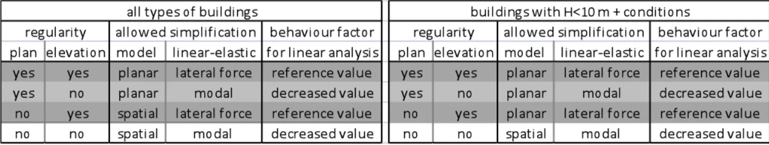
Many design methods can be used in the actual codes, linear-elastic analysis such as classical modal response spectrum analysis (including or not a linearization of behavior factor) or simplified method as lateral force method, or nonlinear methods such as pushover or non-linear time history analysis. Figure 1 presents these methods in relation with Eurocode 8 prescriptions (seismic european code [7]). To take into account the torsion, several ways can be used, for example Eurocode 8 proposes a simplified wide-ranging method or a method based on additional moment calculated for each level of mass. These torsion methods can be used as well as for linear and non-linear analysis. The application of these methods, global analysis and torsion closely depends on the dimensions of modeling (2 x 2D or 3 x 2D, or 3D); Eurocode 8 requirements are reported on table 1. Grey lines in table 1 correspond to the configurations adapted to the approach developed in this paper.
Accurate methods exist to take into account the influence of torsion effects; Chateauneuf and Badaoui [8] carried study with an artificial neural network coupled with Monte Carlo simulations. The approach used in this paper is based on a simple approach with a less wide field than wide-ranging Eurocode proposal; it is based on Priestey and Paulay developments for reinforced concrete with vertical continuous bracings [7] [12]. This method is adapted to timber structures and an application is carried out in order to build a data base able to propose a general coefficient of torsion incidence only based only on a geometric frame considering the positions of the bracing.
Figure 1: possible choices for global analysis in Eurocode 8 requirements
Table1: models, global analysis and behavior factor compatibilities in Eurocode 8 for linear analysis
2. Description of the multi 2D approach
This approach is based on an initial combination of X and Y direction of seismic action. The structure is considered as a set of “lateral load flexible elements” without interruption from the foundation to the top of the building and punctually connected by horizontal diaphragms stiffer and stronger than structural walls
2.1 Continuous bracing requirements
The structural walls can be composed by vertical bracings, shear walls, portal frames... The vertical continuity is assumed between each level and an effective anchorage is considered at the base of the structural wall. These assumptions correspond to design code requirements; adapted detailing must be implemented. The application of this study is based on shear walls, but the method could be applied to other types of structural walls. In the same way, the study is applied to vertical regular buildings for which simplified lateral analysis is adequate to predict the lateral deflexion of the bracing elements. Nevertheless, this approach can be used with a modal spectrum analysis. An example of diaphragm wall composition and anchorage solutions are presented on figure 2 [9].
As example, the shear wall can be composed with an OSB panel (thickness of 13 mm) nailed (diameter of 2.8 mm, fu=600N/mm²) on a 147x47 mm² framing. The basic fastener spacing is s = 75 mm and the framing elements have a design compressive strength parallel to grain of 24 N/mm². In internal environment the seismic strength of this shear wall (height, h = 2800 mm, length = 1100 mm) is equal to 10.6 kN. Figure 3 shows the evolutions of the strength and the stiffness of this type of shear walls versus their length according to Eurocode 5 (timber structure european code) [10].
Figure3: mechanical characteristics of typical shear walls used in this study
2.2 Combination of 2D actions and horizontal diaphragm hypothesis
To be able to combine the seismic actions from two distinct directions, these directions must correspond to two effective direction of bracing, as illustrated in figure 4. The combination is based on linearized behaviour and classical Newmark assumptions. In order to justify these hypotheses roof and floor components have to be much stiffer than walls. This hypothesis can be easily reached with reinforced concrete slabs, but it is more difficult to verify such condition for timber floors. APA guides [11] give some elements about the evaluation of the horizontal diaphragms behaviour. Fuentes did a presented recently comparison between such evaluation and finite element modelling results [15] In a first approach, and regarding Fuentes results, for dwellings or office buildings the ratio between floor area and opening for vertical circulation is high enough to be able to check the stiffness condition. Figure 4 gives an example of the possible shear wall implantation on the directions X and Y. Thus, for each direction five zones are defined direction: A, BC and D. Zones A are close to the façades. Zone D is central and zones BC are between the zones A and D. Figure 4 also exhibits a “reference rectangle” in which the plan of the building floor can be inserted. The slenderness of this rectangle is limited to 2 for this study and the ratio between each lack area and reference rectangle one is limited to 10%.
2.3 multi 2D approach and accidental eccentricity effects
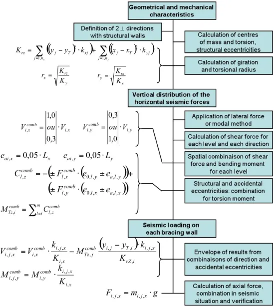
On the base of such plan, structural eccentricity between the centre of mass and the centre of torsion can be calculated. Combinations of seismic action, of geometrical accidental eccentricities, of actions in seismic situation are synthesized on the flowchart in figure 5. This approach was presented by Priestley and Paulay for reinforced concrete [12]. Figure 5 presents the adaptation of this approach using the Eurocode requirements.
Figure 5: flowchart of torsion calculation respecting Eurocode 8 requirements
In this flowchart, k represents the in plan rigidity of a bracing element, K, the rigidity of the whole bracing in x or y direction and Krz the rigidity of the totality of x and y bracings regarding the behaviour in torsion. In plan position of bracings are
represented by the x and y values of the coordinate of their geometrical centre reported to the centre of torsion (xT, yT) and the
radius of torsion are represented by r. The structural eccentricity is called e0 and the accidental one, ea. The shear force, the
bending moment and the moment of torsion are respectively called V, M and C for each floor and MT on the base of the
building. Vi,x is the shear force at the level i in x direction, Vi,j,x is the shear force for the bracing j at the level i in the x
3. Parametric position of bracing
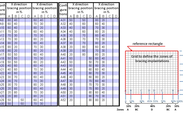
In order to take into account the influence of structural implantation on seismic loadings of the bracing elements, a parametric study has been carried out. Part of tested configurations is presented in table 2. For each position of bracing per zone, different distribution of symmetry inside the zone are studied from 1/2 – 1/2, to 4/5 – 1/5 in zone A and from 1/2 – 1/2, to 1/1 – 0/1 in other zones; these parameters are only geometrical ones. This way is quite easier to calculate than eurocode way which can be difficult or impossible to solve. Effectively, torsional radius and radius of gyration can be quite difficult to determine [13].
In addition to the limits of bracing implantation in one direction (minimum of 20% in zone A), a complementary criterion is imposed in the other direction: (minimum of (100-20) % in zone A. Only some of the configurations presented in table 2 are covered by the plan regularity criteria of Eurocode. This last condition is not respected in all cases presented in table 2. These cases are studied for different slenderness of the “reference rectangle”. Percentages of bracing in Y direction placed in B position (table 2) are also studied in C and D positions. Thus a total of 32 400 configurations have been studied.
Table 2: example of parametric position of bracings
4. Parametric study results
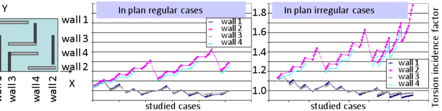
For each configuration of bracing, 16 combinations of seismic actions and accidental eccentricities are computed. For each set of bracing implantation, the maximum value of loading is recorded for each line of bracing. These maxima are plotted on graphs in figure 6. The lines of bracing are numbered in x and y direction: 1 and 2 for lines close to façades and 3 and 4 for BC or D zones. Results are split in regular and irregular cases regarding in plan Eurocode 8 criteria. Even if 1.45 (maximum value of factor incidence for regular cases) is significantly lower than 1.88 (maximum value for irregular cases), wide differences are exhibited on regular case graph and on figures 6 and 7. More discriminant criteria must be found.
Figure 6: example of result as torsion incidence for regular and non-regular configurations for X 60-40 / Y 80-20 and a rectangle slenderness of 1.5
Figure 7: distribution of torsion incidence for: a) regular configurations and for b) irregular configurations
5. Bracing distribution classes and choice of class limits
Average values and coefficients of variation are reported in table 3. Slenderness, B-C and D positions of bracing in y direction, positions for x bracings are single parameters which are not able to find a discriminant criterion even for 7 ranges for positions of X bracing. A combination of parameters as “distribution” is presented in the last line of table 3. Inside each distribution (I, II, III and IV) the coefficient of variation is lower than the values obtained for single parameters and the average values obtained for each distribution are sensibly different with only 4 types of distributions. May be it could be possible to join III and IV distributions.
The distributions are defined as followed:
- distribution I, ½ - ½ perfect symmetry in each zone and each direction
- distribution II, ⅔ - ⅓ for one zone in one direction, ½ - ½ in others zones and direction - distribution III, ¾ - ¼ in one zone except zone A, ½ - ½ in others zones and direction,
or
two zones in ⅔ - ⅓ and two zones in ½ - ½ - distribution IV, the four zones in ⅔ - ⅓
or
3 zones in ½ - ½ and 1-0 in zone D.
The ratios, ½ - ½, ⅔ - ⅓, ¾ - ¼ and 1-0 are ratios in symmetry inside a couple of zones; for example, in X direction in the two zones BC, with 14 meters of shear wall in one side and 6 meters in the other side, the ratio will be 70%-30%, so it could be classed as ¾ - ¼ in this zone.
In order to take into account the results of this work in a design practice or a verification stage, maximum values of torsion influence must be applied instead of average value (table 4). These maximum values are presented in table 4.
Table 4: impact factor of torsion on the loading of bracing regarding its implantation
6. Conclusion
This study analyzed us to analyse the influence of the in plan distribution of bracing on their loadings in seismic situation. The calculation is based on a 3D approach as used in New Zealand and also as proposed in one of the global analysis methods of Eurocode 8. This approach includes the structural and the accidental origin of torsion phenomenon and a data base is build with more than 30 000 simulations corresponding to various implantations, inside a grid defining the “zones” of the bracing positions. This study is applied on timber structures with shear walls but the approach can be extended to other types of bracings and other types of materials. The most influent parameter among the slenderness of the plan, the symmetry of the bracing, and the implantation zones is a combination of the symmetry and the implantation. This combination is here illustrated by four “distributions”. The interest of these distributions is their simple geometric character, which can be read on a plan and the zone grid. With this study, a minimum impact of torsion of 15% is observed even for symmetric configuration and this torsion influence reach 60% for the lowest symmetry configurations taken into account in the study. This threshold of 60% can be exceeded for asymmetric configurations out of the limits defined by the distribution IV.
This study has been completed by a finite element study with linear elastic behavior and also with a neural network able to integrate random values of accidental eccentricity; these numerical approaches are completed by experimental approaches on reduced models.
7. References
[1] Mazaheri D., Mouroux P. et al, Le séisme du Kocaeli (Izmit, Turquie) 17 août 199, Rapport de la mission AFPS, 1999, 132 p.
[2] Méneroud J.P., Betbeder-Matibet J. et al, Le séisme de Hyogo-Ken Nambu (Kobé, Japon) 17 janvier 1995, Rapport de la mission AFPS, 1995, 173 p.
[3] Sidaner J.F., Fournely E., Le séisme de Chuetsu Oki (Kashiwazaki, Japon) 16 juillet 2007, Rapport de al mission AFPS, 2007, 176 p.
[4] Thanoon W.A., Paul D.K., Jaafar M.S., Trikha D.N., influence of torsion on the inelastic response of three-dimensional r.c; frames, Finite Elements in Analysis and Design, v40-5-6, march 2004, p. 611-628.
[5] Stathopoulos K.G., Anagnostopoulos S.A., Accidnetal design eccentricity: is it important for the inelastic response of buildings to strong earthquakes?, Soil Dynamics and Earthquake Engineering, v30-9, sept 2010, p. 782-797.
[6] Thanh Kien Vu T.K., Incidence de la torsion sur la résistance sismique de bâtiments courants avec diaphragmes horizontaux rigides – Application aux structures en bois, PhD thesis, decembre 2011, 200 P.
[7] CEN-TC250, Eurocode 8 : Calcul des structures pour leur résistance aux séismes – Partie 1 : Règles générales, actions sismiques et règles pour les bâtiments, version EN 1998-1.
[8] Badaoui M., Chateauneuf A., Fournely E., Bourahla N., Bensaïbi M., Evaluation of accidental eccentricity for buildings by artificial neural networks, structural engineering and mechanis, vol 41, N° 4 2012, 527-538.
[9] Gianquinto M., Fournely E. et al, Guide des dispositions constructives parasismiques des ouvrages en acier, béton, bois et maçonnerie conforme aux Eurocodes, Presse de ponts et chaussées, 2011, 385 pages
[10] CEN-TC250, Eurocode 5 : Conception et calcul des structures en bois – Parie 1.1 : généralité – règles communes et règles pour les bâtiments, 2004
[11] APA, Diaphragms and shear walls – Design and construction guide. The Engineered Wood Association, 2007.
[12] Paulay T., Priestley M. J. N., Seismic design of reinforced concrete and masonry buildings – Reinforced concrete ductile frames, elastic analysis for lateral forces, Wiley pp168-171, 1992
[13] Fardis M.N., Tsionis G., Specific rules for design and detailing of concrete buildings-Design for DCM and DCH – Illustration of elements design, Seismic design of building, Lisbon, Portugal, February 2011.
[14] Xi C., Construction parasismique – règles simples pour les petits bâtiments en ossature bois, Mémoire d’ingénieur Polytech’Clermont-Ferrand, 2007.
[15] Fuentes S., Fournely E., Bouchair A., Rigidité et distribution des efforts dans un plancher-diaphragme en bois, 8ème Colloque national AFPS, septembre 2011, École des Ponts ParisTech Paris.
![Figure 4: example of timber building with typical position of bracing (partition for office buildings) [14]](https://thumb-eu.123doks.com/thumbv2/123doknet/14644977.549994/4.918.88.835.197.429/figure-example-building-typical-position-bracing-partition-buildings.webp)