Publisher’s version / Version de l'éditeur:
Journal of Thermal Spray Technology, 14, 1, pp. 67-76, 2005-03-01
READ THESE TERMS AND CONDITIONS CAREFULLY BEFORE USING THIS WEBSITE. https://nrc-publications.canada.ca/eng/copyright
Vous avez des questions? Nous pouvons vous aider. Pour communiquer directement avec un auteur, consultez la première page de la revue dans laquelle son article a été publié afin de trouver ses coordonnées. Si vous n’arrivez pas à les repérer, communiquez avec nous à PublicationsArchive-ArchivesPublications@nrc-cnrc.gc.ca.
Questions? Contact the NRC Publications Archive team at
PublicationsArchive-ArchivesPublications@nrc-cnrc.gc.ca. If you wish to email the authors directly, please see the first page of the publication for their contact information.
NRC Publications Archive
Archives des publications du CNRC
This publication could be one of several versions: author’s original, accepted manuscript or the publisher’s version. / La version de cette publication peut être l’une des suivantes : la version prépublication de l’auteur, la version acceptée du manuscrit ou la version de l’éditeur.
For the publisher’s version, please access the DOI link below./ Pour consulter la version de l’éditeur, utilisez le lien DOI ci-dessous.
https://doi.org/10.1361/10599630522729
Access and use of this website and the material on it are subject to the Terms and Conditions set forth at
Process temperature/velocity-hardness-wear relationships for
high-velocity oxyfuel sprayed nanostructured and conventional cermet
coatings
Marple, Basil R.; Lima, Rogerio S.
https://publications-cnrc.canada.ca/fra/droits
L’accès à ce site Web et l’utilisation de son contenu sont assujettis aux conditions présentées dans le site LISEZ CES CONDITIONS ATTENTIVEMENT AVANT D’UTILISER CE SITE WEB.
NRC Publications Record / Notice d'Archives des publications de CNRC:
https://nrc-publications.canada.ca/eng/view/object/?id=71ec20f8-45eb-4698-929f-eb8e3d1878da https://publications-cnrc.canada.ca/fra/voir/objet/?id=71ec20f8-45eb-4698-929f-eb8e3d1878daProcess Temperature/Velocity-Hardness-Wear
Relationships for High-Velocity
Oxyfuel Sprayed Nanostructured and
Conventional Cermet Coatings
Basil R. Marple and Rogerio S. Lima
(Submitted December 16, 2003; in revised form December 20, 2004)
High-velocity oxyfuel (HVOF) spraying of WC-12Co was performed using a feedstock in which the WC phase was either principally in the micron size range (conventional) or was engineered to contain a signifi-cant fraction of nanosized grains (multimodal). Three different HVOF systems and a wide range of spray parameter settings were used to study the effect of in-flight particle characteristics on coating properties. A process window with respect to particle temperature was identified for producing coatings with the highest resistance to dry abrasion. Although the use of a feedstock containing a nanosized WC phase produced harder coatings, there was little difference in the abrasion resistance of the best-performing conventional and multimodal coatings. However, there is a potential benefit in using the multimodal feedstock due to higher deposition efficiencies and a larger processing window.
Keywords high-velocity oxyfuel, nanostructured, process-property-performance relationships, WC-12Co
1. Introduction
The engineering of thermal spray coatings consisting of nanostructured components is being used as a means of improv-ing various properties. The goal is to attain performance levels above those of coatings having a similar chemical and phase composition but a larger scale of microstructure. The rationale behind this approach lies in the potential improvements arising from changes associated with decreasing the grain size. For ex-ample, as the grain size of a material reaches the nanoscale, the fraction of material (number of atoms) located at the grain boundaries (compared with the fraction within the grains) can become significant. This can have an important effect on the way the material behaves and can impart characteristics not ob-served at larger grain sizes. For two-phase or multiconstituent materials, a finer particle size permits more intimate mixing, providing the possibility of having a more uniform distribu-tion of the components within the structure. A high level of homogeneity can be an advantage for some applications where consistent properties from point to point within the body are required.
Various relationships point to the potential for improved me-chanical properties at smaller grain sizes. The Petch relationship for yield strength (Ref 1):
y= i+ BⲐd 1Ⲑ2
(Eq 1) where iis the friction stress, B is a constant, and d is the grain
size, predicts increasing yield strength for decreasing grain size. Because the standard relationship between hardness (H) and yield stress (y) can be given as (Ref 2):
H = 3 y (Eq 2)
where an increase in yield stress accomplished by reducing the grain size should lead to higher hardness values in some mate-rials. Also, if the size of flaws present within a material is related to the scale of the microstructure, the Griffith relationship for the growth of a sharp crack (Ref 3):
f=关2␥EⲐ共c兲兴 1Ⲑ2
(Eq 3) where fis the fracture stress, ␥ is the surface energy associated
with the crack, E is the Young’s modulus, and c is the length of the crack, predicts that the stress required to propagate the initial cracks will increase with a decrease in the scale of the micro-structure.
For these and other reasons, the level of research activity cen-tered on nanostructured materials has increased dramatically in recent years. In the area of thermal spray, there has been a push to investigate whether the potential benefits of nanostructured coatings suggested by the various relationships can be realized and reflected in higher levels of performance (Ref 4-7). Studies on the mechanical properties and performance of various nano-structured coating compositions have produced a wide range of
The original version of this article was published as part of the ASM Proceedings, Thermal Spray 2003: Advancing the Science and Applying the Technology, International Thermal Spray Conference (Orlando, FL), May 5-8, 2003, Basil R. Marple and Christian Moreau, Ed., ASM International, 2003.
B.R. Marple and R.S. Lima, National Research Council of Canada, Industrial Materials Institute, 75 de Mortagne Boulevard, Boucherville, Quebec, Canada J4B 6Y4. Contact e-mail: basil.marple@nrc.ca.
JTTEE5 14:67-76
DOI: 10.1361/10599630522729 1059-9630/$19.00 © ASM International
Peer
results (Ref 8). Of course, this is due in part to the fact that coat-ing quality is influenced by the spraycoat-ing parameters used durcoat-ing deposition. It arises also because both the physical characteris-tics (e.g., morphology, structure, grain size, and density) and chemical properties (e.g., elemental and phase composition) of the feedstock affect coating properties. Because feedstocks con-taining nanostructured phases are under development, there is often a considerable lot-to-lot variation as producers seek to op-timize both the material characteristics and manufacturing pro-cess and to establish adequate quality-control procedures.
The present work, previously summarized elsewhere (Ref 9), focuses on the thermal spraying of WC-12Co feedstocks using high-velocity oxyfuel (HVOF) systems and a wide range of spray parameters. This cermet composition is widely used in ap-plications requiring wear resistance, owing to properties im-parted to the material by combining a hard ceramic phase (WC) and a tough metal phase (Co). Both conventional feedstocks and a feedstock engineered to contain a significant fraction of nano-sized WC grains are included in this study. The objectives are (a) to establish for each spray system the relationships among the processing conditions, the coating properties, and coating per-formance in abrasion, (b) to compare coatings produced from conventional feedstocks to those deposited using powders con-taining a nanosized phase, and (c) to compare the different HVOF systems and the characteristics of the coatings produced with each.
2. Experimental Procedure
2.1 Coating Deposition and Particle Diagnostics
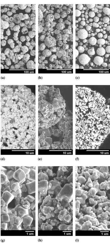
Three commercially available WC-12Co powders were used in the study. Information on these three materials is presented in Table 1. For all three powders, the final steps in the manufactur-ing process involved agglomeration and sintermanufactur-ing treatments. This resulted in products having spherically shaped agglomer-ates. One powder (M-5), termed by the manufacturer as multi-modal, had actually been engineered to have a bimodal WC grain size distribution. It consisted of a 50-to-50 mixture of two size fractions: coarse grains of 1 to 3 µm and fine grains of 30 to 50 nm. The WC grains in the conventional powders were typi-cally under 5 µm in size. Micrographs of the three powders are presented in Fig. 1 at low (Fig. 1a-c), medium (Fig. 1d-f), and high (Fig. 1g-i) magnification. The micrographs show that the C-1 material and, although less pronounced, the C-2 powder had a blocky internal structure (Fig. 1g and h). The multimodal feed-stock was composed of less angular grains (Fig. 1i) and, as ex-pected, a finer structure than the other two materials. The fine
grains present in the multimodal powder are more clearly evi-dent in the high-magnification micrographs shown in Fig. 2.
As indicated in Table 1, three different HVOF spray systems were used to produce coatings. Two of the guns (DJ2600 and DJ2700, Sulzer Metco Inc., Westbury, NY) have a similar de-sign and operate using air cooling and axial injection of the feed-stock. The fuel used for combustion is either hydrogen (DJ2600)
Table 1 Details of WC-12Co powders used for producing coatings Powder designation Particle size, µm WC size designation Gun(s) employed C-1 (a) 15-45 Conventional JP5000 C-2 (b) 11-58 Conventional DJ2600, DJ2700 M-5 (c) 5-40 Multimodal JP5000, DJ2600, DJ2700 (a) 1342VM, Tafa Inc., Concord, NH. (b) SM5812, Sulzer Metco Inc., West-bury, NY. (c) Nanomyte M-5, Nanopowder Enterprises Inc., Piscataway, NJ.
Fig. 1 Micrographs of the WC-12Co feedstock powders showing the external and internal structure of agglomerates for powder C-1 (a), (d), and (g), powder C-2 (b), (e), and (h), and powder M-5 (c), (f), and (i)
Peer
or propylene (DJ2700). The third HVOF system (JP5000, Tafa Inc., Concord, NH) has a different design and operates using water-cooling and radial injection of the powder. Kerosene is used as the fuel for this gun. The conventional powders selected for use with each gun had been manufactured by the same com-pany that produced the gun. The multimodal feedstock was sprayed using all three HVOF guns.
For each gun-feedstock combination, a series of values was used for several of the spray parameters so that the in-flight tem-perature and velocity achieved by the particles during spraying varied over a relatively wide range. A diagnostic system (DPV-2000, Tecnar Automation, St. Bruno, PQ, Canada) was used to determine the average in-flight temperature (using two-color py-rometry) and velocity (using a time-of-flight method) of the par-ticles for all parameter sets shown in Tables 2 to 4. For this work, to reduce material consumption the feed rate used with the vari-ous powders was approximately 6 g/min. Measurements indi-cated that the in-flight particle characteristics determined at these lower powder flow rates were comparable to those pro-duced at the higher flow rates used for depositing coatings. Fol-lowing these diagnostic measurements, coatings were produced using each of the parameter sets shown in Tables 2 to 4. In all cases, air cooling was used to maintain the substrate (low-carbon steel) temperature below 250 °C during spraying, as determined using a pyrometer. The thickness of coating deposited for the various powder-gun combinations ranged from 215 to 525 µm.
Table 2 Spray parameter values used with the JP5000 system for powders C-1 and M-5
Parameter set Oxygen (a), L/min Kerosene, L/h Standoff distance, cm 1 1030 18.9 20.3 2 1030 15.1 38.1 3 1030 22.7 20.3 4 1120 27.3 38.1 5 1190 23.5 20.3 6 1120 20.4 20.3 7 1030 15.1 20.3 8 980 16.3 20.3 9 1190 23.5 38.1 10 1030 18.9 38.1 11 1030 22.7 38.1 12 1120 20.4 38.1 13 1220 27.3 38.1 14 1220 25.0 38.1 15 1190 26.1 38.1 16 1120 18.2 38.1
Note: Fixed parameters: powder feed rate 75 g/min; scan speed 61 cm/s; step size 0.51 cm. (a) Estimated precision ±5%
Table 3 Gas flow rates (in L/min) employed for producing coatings using the DJ2700 with powders C-2 and M-5
Parameter
set Oxygen Propylene
Air (shroud) Nitrogen (carrier) 1 307 62.3 371 15.1 2 300 91.6 354 15.1 3 232 103.8 379 15.1 4 232 62.3 388 23.6 5 293 95.8 345 23.6 6 232 47.7 286 23.6 7 232 47.7 345 23.6 8 232 47.7 388 23.6
Note: Fixed parameters: standoff distance 22.9 cm; powder feed rate 40 g/min; scan speed 76 cm/s; step size 0.25 cm
Table 4 Gas flow rates (in L/min) employed for producing coatings using the DJ2600 with powders C-2 and M-5
Parameter
set Oxygen Hydrogen
Air (shroud) Nitrogen (carrier) 1 195 618 328 15.1 2 267 750 328 15.1 3 267 618 328 23.6 4 195 618 396 23.6 5 231 563 286 23.6 6 231 773 286 23.6 7 195 563 286 23.6 8 195 563 396 23.6 9 195 563 354 23.6 10 144 387 286 23.6
Note: Fixed parameters: standoff distance 22.9 cm; powder feed rate 40 g/min; scan speed 76 cm/s; step size 0.25 cm
Fig. 2 Micrographs taken at a magnification level of (a) 50,000× and (b) 100,000×, showing the presence of fine grains in the M-5 (multimo-dal) WC-12Co feedstock powder
Peer
The deposition efficiency (DE) was determined for each set of coating conditions by depositing on substrates of the same composition (low-carbon steel) as that used in producing the samples. Deposition on these grit-blasted substrates of known dimensions was performed using a predetermined powder feed rate, torch speed, and total number of passes. The DE could be calculated by comparing the weight of the substrate before and after the deposition with respect to the powder feed rate.
2.2 Coating Characterization
Various aspects of the coatings were studied to aid in inter-preting the results of the wear tests (see Section 2.3). Microstruc-tural features were identified using a field emission scanning electron microscope (model S4700, Hitachi Instruments Inc., Tokyo, Japan). For this work, samples were sectioned using a precision saw, mounted under vacuum with an epoxy resin, and submitted to standard metallographic procedures to produce a polished cross section. Porosity levels were assessed with the aid of image analysis software (NIH Image, public domain soft-ware) on the images obtained (magnification 500×) using a scan-ning electron microscope (JSM-6100, JEOL, Tokyo, Japan) in the backscattered mode under conditions of contrast to enhance the pores. An average value of porosity was determined for each coating from the results of ten separate analyses. The phases present within the various coatings were determined by x-ray diffraction (XRD) analysis (model D8, Bruker AXS, Karlsruhe, Germany) employing CuK␣ radiation, a step size of 0.1°, a step time of 5 s, and a 2 scan window from 25 to 55°. The hardness values for the coatings were determined using a microhardness tester (Micromet II, Buehler, Lake Bluff, IL) equipped with a Vickers diamond pyramid indenter operating under a 300 g load. The average microhardness number on the cross section of a coating was calculated from the results of ten indentations.
2.3 Abrasion Testing
Wear tests were carried out using standard procedures (Ref 10) and equipment (Falex Abrasion Tester, Falex Corp., Aurora, IL) to evaluate the resistance of the coatings to dry abrasion. Briefly, these tests involved feeding (300 g/min) silica sand (212-300 µm, U.S. Silica Co., Ottawa, IL) between a stationary coated specimen (ground to a surface finish of Ra= 0.3 µm) and
a rotating (200 rpm) rubber-coated wheel, while maintaining a force of 130 N between the two contacting surfaces. Each test was continued until the equivalent lineal abrasion distance reached 4309 m. Two samples were tested for each of the coat-ings produced with the various spray-parameter/gun com-binations. The volume of material abraded away during a test was determined from the wear scar using optical profilometry (Ref 11).
3. Results and Discussion
3.1 Particle DiagnosticsThe results for the in-flight particle diagnostics for the three HVOF systems are presented in Fig. 3 for the multimodal (Fig. 3a) and conventional (Fig. 3b) powders. These plots exhibit the
expected trend of increasing particle velocity with increasing particle temperature. The dependence of velocity on tempera-ture was stronger for the DJ systems (Sulzer Metco) than for the JP5000 (Tafa Inc.), as reflected in the higher slopes for the ve-locity-temperature (v-T) lines for the DJ guns. As can be seen by comparing the two graphs, the multimodal powder tended to travel at a higher velocity for a given particle temperature. (Note that the range of velocity values represented on the velocity axis is different for the two graphs.) This difference between the two powders was greater for the DJ systems than for the JP5000. For example, at a particle temperature of 1600 °C with the JP5000, the multimodal particles were traveling at a velocity that was less than 10% above that of the conventional powder. For the DJ systems, which tend to produce higher particle temperatures, a comparison between the two powders at 1950 °C revealed that the multimodal powder had an average particle velocity of more than 20% above that of the conventional powder.
Fig. 3 The results of in-flight particle diagnostics showing the rela-tionship between particle velocity and temperature during the HVOF spraying of (a) multimodal and (b) conventional WC-12Co powders. The legend identifies the gun and the distance from the torch exit at which the data was collected.
Peer
Comparing the results for the two DJ systems, the DJ2600 (hydrogen) torch produced higher velocities for a given particle temperature than did the DJ2700 (propylene) gun. It could also be seen that the v-T particle characteristics at the two standoff distances used for the JP5000 were somewhat different. These differences were more pronounced for the multimodal powder (Fig. 3a), which had a higher fraction of small particles. Details of these differences can be seen in Fig. 4 where the temperature (Fig. 4a) and velocity (Fig. 4b) profiles as a function of distance from the torch exit are shown for the multimodal powder. For the three sets of spray parameter combinations studied, the maxi-mum particle temperature and velocity were reached at a dis-tance of approximately 20 cm from the torch exit. Beyond this point, the particles tended to cool and decrease in velocity. As shown in Fig. 4, the decrease in the values depended on the pa-rameter settings used, being as small as 50 °C and 55 m/s (pa-rameter set 4) and as large as 165 °C and 125 m/s (pa(pa-rameter set 2). It is important to note that the values reported in Fig. 3 and 4(a) represent the average temperature at the surface of the par-ticles. While the surface temperature of the particles is decreas-ing as they travel the distance from 20 to 38 cm, this may be accompanied by heat transfer to the core, producing more uni-formly heated particles.
3.2 Deposition Efficiency
A plot of the deposition efficiency (DE) as a function of in-flight particle temperature is shown in Fig. 5. Several
observa-Fig. 4 Variation in in-flight particle (a) temperature and (b) velocity with distance from the torch exit when spraying a WC-12Co multimodal powder using the JP5000 system. The values for the different parameter sets are given in Table 2.
Fig. 5 The DE for WC-12Co powders sprayed by HVOF as a function of (a) particle temperature and (b) particle velocity. The legend indicates the gun/standoff distance (in centimeters)/powder combination used.
Peer
tions can be highlighted. Comparing the two powders, it is evi-dent that the DE for the multimodal powder (solid symbols) was generally higher than that for the conventional powders (open symbols). In the case of the JP5000 gun, this difference was ap-proximately 10%. For the DJ systems, the difference could be much higher (>25%). It was also noted that for particle tempera-tures above approximately 1500 °C, there was not a strong effect of particle temperature on DE for the conventional powder with all spray systems, and for the multimodal powder with the JP5000. However, for the multimodal powder with the two DJ systems, there was a strong dependence of DE on particle tem-perature; the DE varied by more than 30% over a relatively nar-row temperature range. The maximum in DE of over 80% for the multimodal powder was obtained under conditions that pro-duced a particle temperature of approximately 1850 to 1900 °C. Above that temperature, the DE declined. The highest DE ob-tained with the conventional powders for the different spray sys-tems was 45 to 50%. A final observation for the JP5000 system was that the DE at a spray distance of 38.1 cm tended to be greater than that at 20.3 cm for a given particle temperature. It should be noted that the WC phase of these cermet materials remains solid during the spraying step. It is only the metal frac-tion that melts. As menfrac-tioned above, it is believed that although the maximum particle surface temperature is reached at a dis-tance of approximately 20 cm from the torch exit, heat transfer to the internal region of particles may result in more uniform melt-ing at a distance of 38 cm. These more uniformly melted (softer) particles would be more easily incorporated into the coating; whereas, a higher fraction of less uniformly heated (harder) par-ticles present at 20 cm would tend to rebound off the substrate surface.
The higher DE values found for the multimodal feedstock are of interest due to the potential of reduced cost in producing coat-ings. The reason for these higher values is believed to be asso-ciated with the broader distribution of the carbide size and the higher velocities achieved during spraying. The smaller carbide size would allow for more intimate mixing with the metal phase and a greater likelihood of particles depositing on the substrate. For a more complete understanding of the exceptionally high DE obtained under some conditions, further work is required to de-termine how the spray conditions, in-flight particle characteris-tics, and feedstock structure influence these values.
3.3 Coating Porosity
A plot showing the level of porosity in the various coatings as a function of the in-flight particle temperature is presented in Fig. 6. For all values of particle temperature obtained with the conventional powder (C-1) sprayed with the JP5000, the coat-ings had low porosity levels (<1%) at both standoff distances used. When the DJ systems were used to deposit conventional powder (C-2), porosity levels of 1% and lower were obtained when the average particle temperatures were above 1850 °C. For the multimodal powder sprayed with the JP5000 at a standoff distance of 20.3 cm, there was no significant dependence of po-rosity on average particle temperature under the conditions evaluated in the current study. For this same gun at a standoff distance of 38.1 cm, the level of porosity tended to decrease to below 1% when the particle temperature during spraying was greater than approximately 1800 °C. The two DJ systems
exhib-ited a comparatively strong influence of particle temperature on porosity when spraying the multimodal powder. Several of these coatings had porosity levels above 4%. It was only when particle temperatures approached 2100 °C that coatings with porosity levels below 1% were produced.
It is interesting to relate the porosity in the coatings to DE, as shown in Fig. 7. There was a clear trend, particularly for the DJ guns with the multimodal feedstock, of increasing porosity with rising values of DE. The very high values of DE above 70% obtained using the DJ gun with the multimodal powder come at a cost of porosity levels greater than 3%. The higher DE ob-tained with the DJ systems at a given particle temperature for the multimodal powder compared with the conventional powder may be due to the higher particle velocities (Fig. 3) at a given temperature. The differences observed in DE for these powders with the JP5000 were less pronounced, owing to much smaller differences in particle velocity over a given temperature.
Concerning the porosity-DE relationships, the results for flight particle diameter obtained with the diagnostic system in-dicated that the powder particles fragmented during spraying. This fragmentation may have been due to the turbulent nature of the process or caused by a rupture of the agglomerated particles resulting from rapid heating and high velocity. It was observed that when the multimodal powder was sprayed using the JP5000, the in-flight particle sizes were much smaller than those pro-duced using the DJ systems. The differences in in-flight particle diameter among these three systems were not nearly so marked when spraying the conventional powders.
It is thought that the high DE obtained for the multimodal powder using the DJ systems at intermediate temperatures was related to the broader distribution of the carbide size and higher
Fig. 6 Levels of porosity in HVOF-sprayed WC-12Co coatings pro-duced under a range of spray conditions
Peer
velocities achieved during spraying. However, there was little particle fragmentation under these conditions, and the high de-position rate of large particles was accompanied by the entrap-ment of porosity. As the spray parameter settings were changed, resulting in higher particle temperatures and velocities, the frag-mentation of the particles increased. These smaller, hotter, faster particles produced a denser coating; however, the DE decreased, possibly because the events leading to fragmentation caused some of the material to move to the cooler periphery of the spray jet. Whatever the reason for these results, it is clear that the high DE values for the multimodal feedstock obtained using the DJ systems under some spray conditions are very attractive. An understanding of how to engineer the feedstock so that such high values of DE can be achieved while producing dense coat-ings would be a major step in improving the economics of the process.
3.4 Coating Hardness
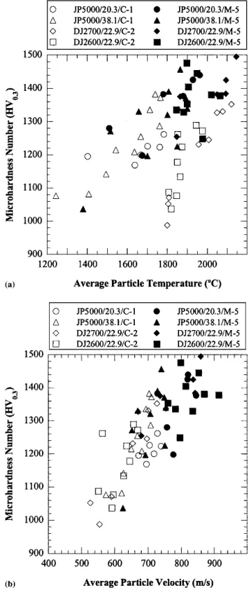
Graphs are presented in Fig. 8 relating the hardness of the coatings to the in-flight particle characteristics. It should be noted that not all of the coatings for which data were shown in Fig. 3 are represented in Fig. 8. In a few cases in which spray parameter settings resulted in relatively low particle tempera-tures, coatings were too brittle for a hardness value to be deter-mined, due to spalling under the indenter tip.
There was a general trend of increasing hardness with in-creasing particle temperature (Fig. 8a) and velocity (Fig. 8b) for the different powders and HVOF systems. The figures also show that the hardest coatings were produced using the multimodal powder (solid symbols). For each HVOF system, multimodal
coatings with microhardness numbers above 1400 were pro-duced. The hardest coating had a microhardness number ap-proaching 1500. In contrast, all of the coatings produced using the conventional powders had microhardness numbers of less
Fig. 7 Relationship between the level of porosity in HVOF-sprayed WC-12Co coatings and the DE
Fig. 8 Relationship between coating hardness and the particle (a) tem-perature and (b) velocity during the HVOF spraying of WC-12Co pow-ders
Peer
than 1400. The only spray system not to show a clear increase in hardness with respect to particle temperature and velocity was the DJ2600, when using the multimodal powder.
It is also apparent in Fig. 8 that a wide range of coating hard-ness values can be obtained with the same feedstock and thermal spray system, depending on the spray parameters. For example, when the JP5000 system was used to spray the multimodal pow-der (M-5), the hardness numbers of the resulting coatings ranged from ∼1040 to 1450. Similarly, the coatings produced using the DJ2700 and conventional powder (C-2) had hardness numbers ranging from less than 1000 to 1350. In light of these results, it is not surprising that for coatings produced using a given feedstock chemistry, a wide range of hardness values can be found in the literature. These arise not only due to the use of different sets of spray parameters, but also due to differences in feedstock char-acteristics and in the spray system used to deposit the coatings.
3.5 Abrasion Resistance
Results from the abrasion tests are shown in Fig. 9. There was a general tendency of increasing abrasion resistance (lower vol-ume loss) with increasing hardness. However, this trend was not always observed for specific systems. For example, when using the DJ2700 system with both the conventional and multimodal powders, a least squares fit of the data revealed increasing wear with increasing coating hardness. This may be related to the higher temperatures associated with the conditions used to
pro-duce these coatings, which can lead to degradation of the carbide phase (Ref 12, 13) (Section 3.6). The coatings (both conven-tional and multimodal) produced using the JP5000 system were among the best performing in terms of abrasion. However, these coatings, particularly those produced using conventional feed-stock, exhibited a much broader range of wear values, indicating a greater sensitivity to the spraying conditions.
It can be observed in Fig. 9 that the best-performing multi-modal and conventional coatings exhibited similar values of abrasive wear. However, there may be some advantage to using the multimodal feedstock due to the possibility of producing relatively high-performance coatings over a broad range of spray conditions. The results show that none of the multimodal coatings (solid symbols) experienced a volume loss greater than roughly 9 mm3(dashed line). Approximately half the conven-tional coatings (open symbols) had volume losses above this value. The possibility of operating over a broad process window is significant because it indicates that the process is robust, which is an attractive feature in production.
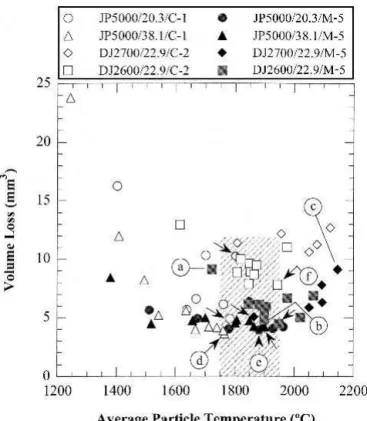
The relationship between the wear (volume loss) of the coat-ings in abrasion and the in-flight particle temperature during de-position is shown in Fig. 10. Despite the different thermal his-tories of the particles sprayed with the different guns, it appears that the results from the in-flight particle diagnostic system can be used to define a process window based on particle tempera-ture within which the best-performing coatings can be produced. The general distribution of the points appears to indicate that there was a minimum in wear when the in-flight particle tem-perature was in the range of ∼1750 to 1950 °C (hatched region).
Fig. 9 Volume of the wear scar as a function of the coating hardness for abrasion tests of HVOF-sprayed coatings. The legend indicates the gun/standoff distance (in centimeters)/powder combination used for spraying. The dashed line denotes the volume loss value below which all multimodal coatings fall.
Fig. 10 The effect of particle temperature during deposition on the wear behavior of HVOF-sprayed WC-12Co coatings. Letters identify coatings for which XRD and/or SEM results are given in Fig. 11 and 12. Arrows denote the best-performing coatings in each group.
Peer
For each gun/distance/powder combination, the best-perform-ing coatbest-perform-ing (i.e., the minimum volume loss, as identified by ar-rows in Fig. 10) was produced under conditions that resulted in in-flight particle temperatures at the point of contact with the substrate in this temperature range. In some cases, the process window was somewhat larger. This can be seen for the JP5000, where coatings having good wear resistance were produced at temperatures as low as 1500 °C. A possible explanation (based on carbide degradation and the formation of new phases) for the maximum in abrasion resistance within a processing window at intermediate temperatures is presented in the next section.
3.6 Phase Composition and Microstructure
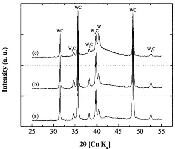
The XRD spectra for three coatings (identified as a, b, and c in Fig. 10) produced with the multimodal powder using the DJ system under conditions that resulted in three different in-flight particle temperatures are shown in Fig. 11. These spectra re-vealed the presence of WC, W2C, W, and an unidentified
amor-phous phase, the levels of which changed with the particle tem-perature. The amount of amorphous phase (at 2 of 37-47°) increased with increasing temperature. It can be observed that the reaction sequence involving the loss of carbon to produce W (i.e., WC → W2C → W) occurred more readily at the highest
temperature (Fig. 11c).
The micrographs of these three coatings, together with those of the best-performing coatings produced for each feedstock ma-terial, are presented in Fig. 12. The micrographs show the effect of particle temperature on coating structure (Fig. 12a-c). At a lower particle temperature, the coating contained a higher level of porosity (Fig. 12a), at an intermediate temperature, the coat-ing was relatively dense (Fig. 12b), and at a high in-flight
par-ticle temperature, the carbide phase was degraded, as evidenced by the presence of metal stringers and the rounding of the WC grains (Fig. 12c). It is also clear that the size of the carbide grains
Fig. 11 The XRD patterns for three multimodal coatings identified in Fig. 10. The materials, deposited using the DJ system, exhibited the following in-flight particle temperature/coating abrasion resistance characteristics. (a) 1721 °C (lowest temperature used with the DJ2600)/ one of the two worst-performing multimodal coatings. (b) 1898 °C/one of the best-performing multimodal coatings produced using the DJ2600. (c) 2147 °C (highest temperature used with the DJ2700)/one of the two worst-performing multimodal coatings
Fig. 12 Backscattered electron SEM images of coatings identified in Fig. 10. (a) to (c) Multimodal coatings produced using the DJ torch. (a) and (b) DJ2600. (c) DJ2700. (d) The best-performing conventional coating (powder C-1) produced with the JP5000 system. (e) The best-performing of all multimodal coatings (produced using the JP5000 at a spray distance of 20.3 cm). (f) The best-performing conventional coating (powder C-2) produced using the DJ2600 system (hydrogen fuel)
Peer
was not the dominant factor in determining the abrasion resis-tance of these coatings. The microstructures of the coatings shown in Fig. 12(d) and (e) reveal a difference in the size of the carbide grains present in the two coatings; however, the coatings exhibited an almost identical abrasion resistance (Fig. 10). The coating in Fig. 12(f), which exhibited a level of abrasion almost twice that of the coatings in Fig. 12(d) and e, has carbide grains that are not that different in size to those of the coating in Fig. 12(d). However, the coating in Fig. 12(f) has grains that are more rounded, indicating greater reaction between the constituents.
The explanation for the variation of wear resistance, as seen both in the overall results and within the different series of coat-ings, lies in the effect of the in-flight particle characteristics on the coating structure and phase composition. At low tempera-tures and velocities, particles are not sufficiently molten and have insufficient kinetic energy to produce good bonding be-tween the splats. This results in a coating with a low cohesive strength. These coatings often chip and spall when attempts are made to indent them. Also, the combination of low temperature and low velocity limits the amount of deformation that occurs upon impact, often producing coatings having a higher level of porosity. At these lower temperatures there is limited reaction between the constituents in the coating. Coatings produced un-der these conditions tend to have a lower abrasion resistance with poorly bonded splats that can be relatively easily removed. As the particle temperature (and velocity) increases, low-porosity, well-bonded, higher-hardness coatings are produced. There is also some dissolution of the WC phase in the Co. This produces a more wear-resistant matrix phase. At higher tem-peratures, reactions that degrade the carbide phase play an in-creasingly important role. While some dissolution of the carbide phase in the cobalt matrix may be beneficial, there is a point beyond which the reaction of the WC to produce increased levels of other species (e.g., W2C and W) is detrimental to the wear
resistance of the coating. This offsets any improvements derived from increases in the cohesive strength of the coating or matrix hardening at higher particle temperatures and velocities.
4. Conclusions
This study of the HVOF thermal spraying of nanostructured multimodal and conventional WC-12Co powders has revealed differences between the coatings produced. Relatively high val-ues of DE (>70%) can be achieved under some conditions using the DJ system to deposit the multimodal feedstock. These DE values are significantly above those obtained using conventional feedstocks. These multimodal coatings produced at a high DE tend to have higher levels of porosity. This suggests that addi-tional work to investigate the possibility of achieving high de-position efficiencies while producing low-porosity deposits is merited.
The multimodal coatings tend to have a higher hardness than conventional coatings; however, in terms of abrasion resistance, there is little difference between the best-performing multimo-dal and conventional coatings. The most wear-resistant coatings produced using various powder-spray system combinations are
those for which the spray parameter settings result in a particle temperature at the point of contact with the substrate in the range 1750 to 1950 °C. Although the width of the ideal process win-dow is different for different powder-spray system combina-tions, at particle temperatures (and velocities) below this win-dow, the cohesive strength of the coatings is lowered, resulting in reduced performance in abrasion. Similarly, at temperatures above the ideal range, degradation of the carbide phase has a detrimental effect on the abrasion resistance.
Another feature of the multimodal feedstock is a relatively large process window, that is, comparatively high-performance coatings can be produced using various HVOF systems over a wide range of spray conditions, offering the possibility of better quality control and improved coating reliability.
Acknowledgments
Technical support from F. Belval for thermal spraying, M. Lamontagne for in-flight particle diagnostics, E. Poirier for wear testing, and M. Thibodeau for XRD and SEM analysis is grate-fully acknowledged. We thank Dr. Salim Bouaricha for his as-sistance in analyzing the XRD data.
References
1. W.D. Kingery, H.K. Bowen, and D.R. Uhlmann, Introduction to
Ce-ramics, 2nd ed., John Wiley & Sons, 1976, p 739
2. A.H. Cottrell, The Mechanical Properties of Matter, Robert E. Krieger Publishing Co., 1981, p 326-332
3. Idem, ibid., 345
4. E.H. Jordan, M. Gell, Y.H. Sohn, D. Goberman, L. Shaw, S. Jiang, M. Wang, T.D. Xiao, Y. Wang, and P. Strutt, Fabrication and Evalua-tion of Plasma Sprayed Nanostructured Alumina-Titania Coatings with Superior Properties, Mater. Sci. Eng., A, Vol 301, 2001, p 80-89 5. J. He and J.M. Schoenung, A Review on Nanostructured
WC-Co-Coatings, Surf. Coat Technol., Vol 157, 2002, p 72-79
6. H. Chen, X. Zhou, and C. Ding, Investigation of the Thermomechanical Properties of a Plasma-Sprayed Nanostructured Zirconia Coating,
J. Eur. Ceram. Soc., Vol 23, 2003, p 1449-1455
7. R.S. Lima, B.R. Marple, K.A. Khor, H. Li, and P. Cheang, Mechanical Properties, Microstructural Characteristics and In Vitro Behavior of APS-Sprayed Nanostructured and Conventional Hydroxyapatite Coat-ings, Thermal Spray 2004: Advances in Technology and Application, May 10-12 2004 (Osaka, Japan), AMS International, 2004, p 157-162 8. Y. Qiao, Y. Liu, and T.E. Fischer, Sliding and Abrasive Wear
Resis-tance of Thermal-Sprayed WC-Co Coatings, J. Thermal Spray
Tech-nol., Vol 10 (No. 1), 2001, p 118-125
9. B.R. Marple and R.S. Lima, Process Temperature-Hardness-Wear Re-lationships for HVOF-Sprayed Nanostructured and Conventional Cer-met Coatings, Thermal Spray 2003: Advancing the Science and
Apply-ing the Technology, B.R. Marple and C. Moreau, Ed., May 5-8, 2003
(Orlando, FL), ASM International, 2003, p 273-282
10. “Standard Test Method for Measuring Abrasion Using the Dry Sand/ Rubber Wheel Apparatus,” G 65-91, Annual Book of ASTM Standards, ASTM, 1994, p 246-258
11. S. Dallaire, M. Dufour, and B. Gauthier, Characterization of Wear Dam-age in Coatings by Optical Profilometry, J. Thermal Spray Technol., Vol 2 (No. 4), 1993, p 363-368
12. H.L. de Villiers Lovelock, Powder/Processing/Structure Relationships in WC-Co Thermal Spray Coatings: A Review of the Published Litera-ture, J. Thermal Spray Technol., Vol 7 (No. 3), 1998, p 357-373 13. C. Verdon, A. Karmimi, and J.-L. Martin, A Study of High Velocity
Oxy-fuel Thermally Sprayed Tungsten Carbide Coatings: Part 1. Mi-crostructures, Mater. Sci. Eng., A, Vol 246, 1998, p 11-24


![[PDF] Tutoriel Painter : Création d'un encadrement | Cours informatique](data:image/gif;base64,R0lGODlhAQABAIAAAP///wAAACH5BAEAAAAALAAAAAABAAEAAAICRAEAOw==)