Publisher’s version / Version de l'éditeur:
Vous avez des questions? Nous pouvons vous aider. Pour communiquer directement avec un auteur, consultez la première page de la revue dans laquelle son article a été publié afin de trouver ses coordonnées. Si vous n’arrivez pas à les repérer, communiquez avec nous à [email protected].
Questions? Contact the NRC Publications Archive team at
[email protected]. If you wish to email the authors directly, please see the first page of the publication for their contact information.
https://publications-cnrc.canada.ca/fra/droits
L’accès à ce site Web et l’utilisation de son contenu sont assujettis aux conditions présentées dans le site
LISEZ CES CONDITIONS ATTENTIVEMENT AVANT D’UTILISER CE SITE WEB.
Surface & Coatings Technology, 201, 16-17, pp. 7589-7596, 2007-02-22
READ THESE TERMS AND CONDITIONS CAREFULLY BEFORE USING THIS WEBSITE. https://nrc-publications.canada.ca/eng/copyright
NRC Publications Archive Record / Notice des Archives des publications du CNRC :
https://nrc-publications.canada.ca/eng/view/object/?id=70f5d007-5e1d-4a42-9ee2-ebf2340bbf88
https://publications-cnrc.canada.ca/fra/voir/objet/?id=70f5d007-5e1d-4a42-9ee2-ebf2340bbf88
NRC Publications Archive
Archives des publications du CNRC
This publication could be one of several versions: author’s original, accepted manuscript or the publisher’s version. / La version de cette publication peut être l’une des suivantes : la version prépublication de l’auteur, la version acceptée du manuscrit ou la version de l’éditeur.
For the publisher’s version, please access the DOI link below./ Pour consulter la version de l’éditeur, utilisez le lien DOI ci-dessous.
https://doi.org/10.1016/j.surfcoat.2007.02.025
Access and use of this website and the material on it are subject to the Terms and Conditions set forth at
Fatigue and mechanical properties of nanostructured and conventional
titania (TiO
₂) thermal spray coatings
Fatigue and mechanical properties of nanostructured and conventional titania
(TiO
2
) thermal spray coatings
A. Ibrahim
a,⁎
, R.S. Lima
b, C.C. Berndt
c,d, B.R. Marple
ba
State University of New York at Farmingdale, Route 110, Lupton Hall, Room 182, Farmingdale, NY 11735 USA b
National Research Council of Canada, 75 de Mortagne Boulevard, Boucherville, QC Canada J4B 6Y4 c
James Cook University, School of Engineering, Townsville, QLD 4811, Australia d
Stony Brook University, Stony Brook, NY 11793, USA
Received 20 August 2006; accepted in revised form 15 February 2007 Available online 22 February 2007
Abstract
Nanostructured and conventional titania (TiO2) coatings were thermally sprayed using air plasma spray (APS) and high velocity oxy-fuel (HVOF) processes. The fatigue and mechanical properties of these coatings were investigated. A previous study characterized these coatings by scanning electron microscopy (SEM) to investigate the microstructural features and Vickers indentation to determine the hardness and crack propagation resistance. This current complementary SEM work examined fracture surfaces of fatigue-tested samples to assess crack nucleation and to study mechanisms of deformations. The fatigue strength of coatings deposited onto low-carbon steel (AISI 1018) showed that the nanostructured titania coated specimens exhibited significantly higher fatigue strength compared to the conventionally sprayed titania. The strain– time curve of AISI 1018 coated with TiO2indicated that the strain amplitude of the HVOF-sprayed nanostructured TiO2coating was much lower than the corresponding data of APS conventional TiO2. SEM analysis of fracture surfaces revealed valuable information regarding the influence of these coatings on the performance of the coated component. This investigation gives new understanding to the nature of fatigue and deformation of the nanostructured and conventional titania (TiO2) coatings.
© 2007 Elsevier B.V. All rights reserved.
Keywords: Fatigue; Nanostructured coatings; Mechanical properties; Thermal spraying; Titanium oxide (TiO2); Strain–time-curve
1. Introduction
Nanostructured materials and coatings offer the potential for significant improvements in engineering properties based on the improvements in physical and mechanical properties resulting from the reduction of microstructural features by factors of 100 to 1000 times compared to present engineering materials. Nanostructured materials can have improved strength, hardness, ductility, toughness, specific heat, and enhanced diffusivity compared to conventional materials [1,2]. Nanostructured thermal spray ceramic oxide coatings, such as Al2O3–TiO2
and TiO2, have demonstrated superior wear performance
compared to related coatings produced from conventional ceramic oxide powders[3,4].
Titania (or titanium dioxide, TiO2) powder is used to
produce hard, dense coatings that resist wear by abrasion or motion. Titanium dioxide can be used for advanced applica-tions such as solar cells, fuel cells, and catalysts [2]. Titania coatings such as these have been applied via air plasma spray (APS), the traditional method of depositing ceramic thermal spray coatings.
The air plasma spray (APS) process has been used for many years to form TiO2 and other ceramic oxide coatings.
This APS process is preferred due to the high temperature of the plasma jet [5], which is necessary to thermal spray high melting point materials in an effective way. During the thermal spraying of ceramic oxides it is necessary to totally or partially melt the powder particles to make coatings. However, TiO2 is a ceramic material that has a relatively low melting
point (1855 °C) [6] and it can be thermally sprayed via the high velocity oxy-fuel (HVOF) process [1,7], which is a
www.elsevier.com/locate/surfcoat
⁎ Corresponding author. Tel.: +1 631 420 2309; fax: +1 631 420 2194.
E-mail address:[email protected](A. Ibrahim). 0257-8972/$ - see front matter © 2007 Elsevier B.V. All rights reserved. doi:10.1016/j.surfcoat.2007.02.025
technique that exhibits relatively low jet temperatures (< 3000 °C) but high velocities[5]. Therefore, HVOF spraying is an alternative method to thermal spray TiO2 to engineer
new types of microstructures.
This paper is a continuation of a previous work [1]
demonstrating that HVOF-sprayed nanostructured titania coatings exhibited superior mechanical behavior compared to APS and HVOF-sprayed conventional titania coatings. It was observed that coatings exhibited similar values of Vickers hardness (about 800 Vickers at a 300 g load), however, the crack propagation resistance (or relative toughness) of the HVOF-sprayed nanostructured titania coating was almost 2 times higher than that of the APS conventional coating and approximately 1.6 times higher than that of the HVOF-sprayed conventional coating. It was proposed that the semi-molten nanostructured particles embedded in the coating microstruc-ture were acting as crack arresters [1], thereby increasing the toughness of the material. Abrasion wear tests (ASTM G65)
[8] indicated that the volume loss of the APS conventional titania coating was 2.4 times higher than that of the HVOF-sprayed nanostructured titania under the same wear conditions. When HVOF-sprayed nano TiO2and APS nano TiO2coatings
were compared in abrasion testing, the volume loss of the APS coating was 1.7 times higher than that of the HVOF-sprayed coating, i.e., the HVOF coating was clearly superior [9], therefore APS nano TiO2 coatings were not fatigue-tested. It
was also found that the bond strength (ASTM C633) [10]of the HVOF-sprayed nanostructured titania on low-carbon steel substrates was 65% higher than that of the APS conventional titania and 2.4 times higher than that of the HVOF-sprayed conventional TiO2[1]. This data clearly show the mechanical
superiority of the HVOF-sprayed nano TiO2 coating when
compared to those of other TiO2coatings.
An important observation was made during the crack propagation resistance measurements carried out via Vickers indentation (5 kgf)[1], namely, that the HVOF-sprayed coating exhibited an “isotropic” behavior, i.e., four cracks approxi-mately equal in length emanated from the four corners of the Vickers indentation impression. Therefore, the HVOF-sprayed coating behaved in a similar fashion to the bulk material. These results demonstrated that the HVOF spraying of nanostructured TiO2powders was an efficient alternative coating method to the
APS processing of TiO2.
It is widely recognized that thermal spray coatings can significantly influence the fatigue strength of coated compo-nents[11–13]. This paper presents the results of a fatigue and deformation behavior investigation of thermally sprayed nanostructured and conventional titania coatings deposited by different spray processes, specifically HVOF and APS. As previously stated, the mechanical performance and wear behavior of HVOF-sprayed nano TiO2 coatings were much
superior to those of conventional TiO2 coatings sprayed by
HVOF and APS, and nanostructured TiO2coatings sprayed by
APS. It is important to point out that the APS processing of conventional TiO2represents the traditional method currently
used to make TiO2 by the majority thermal spray research
centers, universities and industries. This research has the
objective to identify potential advantages of HVOF spraying nanostructured TiO2 powders in lieu of APS processing of
conventional TiO2for structural applications, mainly the ones
where a high performance coating is paramount. Therefore, to supplement the earlier work on wear behavior, fatigue studies were carried out to further compare the structural performance of HVOF-sprayed nano TiO2 coatings to that of APS
conventional TiO2. In this investigation the air plasma spraying
of conventional titania represents the current and traditional method of ceramic coating application; whereas, the HVOF spraying of nanostructured titania discussed in this current work can be considered an alternative method for applying this material.
2. Experimental procedure
2.1. Feedstock powders
Nanostructured and conventional TiO2 feedstock powders
were employed in this study. The nanostructured feedstock (VHP-DCS (5–20 μm), Altair Nanomaterials, Reno, NV, USA) was agglomerated and sintered. It exhibited a nominal particle size range from 5 to 20 μm,Fig. 1. This feedstock was
HVOF-Fig. 1. (a) Microscopic titania feedstock particle observed at low magnification. (b) Surface of (a) observed at high magnification—individual nanostructured titania particles agglomerated via spray-drying.
sprayed (DJ2700-hybrid, Sulzer Metco Inc., Westbury, NY, USA). The conventional TiO2feedstock powder (Metco 102,
Sulzer Metco, Westbury, NY, USA) was fused and crushed and exhibited a nominal particle size range from 7.8 to 88 μm. This feedstock was APS processed (F4-MB, Sulzer Metco Inc., Westbury, NY, USA).
2.2. Thermal spraying
The HVOF spray parameters were set to produce the highest average particle temperature for each of the two feedstocks selected for the coating. The air plasma sprayed coating was produced on the basis of spray parameters recommended by the manufacturer of the torch and feedstock.
A cooling system of air jets was employed during the spray process to reduce the coating temperature, which was monitored using a single color pyrometer (wave lengths: 8–12 μm; temperature range of 0–500 °C). The pyrometer was previously calibrated by using a reference titania coating. The maximum coating temperature for the air plasma sprayed coating was approximately 150 °C; whereas the HVOF-sprayed coatings were prepared at ∼270 °C.
2.3. Crack propagation resistance
The crack propagation characteristics were determined by indenting the coating cross-section with a Vickers indenter under a 5 kg load for 15 s, with diagonals of the indenter so aligned that one of these was parallel to the substrate surface. The length of the major crack, designated as “2c,” parallel to the substrate surface that originated at or near the corners of the Vickers indentation impression was measured. Based on the indentation load (P) and 2c, the crack propagation resistance was measured according to the relation between load and crack length, P/c3 / 2 [14], where P is in Newtons and c is in meters. All indentations were performed very near the centerline of the cross-section and the average of five measurements was taken to assess the resistance of the coating towards crack propagation.
2.4. Fatigue testing
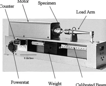
Rotating-beam fatigue testing was conducted on AISI 1018, low-carbon steel. The fatigue-testing machine is an RBF-200, rotating-beam fatigue machine (Fatigue Dynamics Inc., Walled Lake, MI) is shown in Fig. 2. The test specimen used in the fatigue testing (Fig. 3) was a 12.7 mm (1 / 2 in.) hourglass bar prepared according to ASTM E466[15]. The nominal coating thickness was 100 μm (0.004 in.). The fatigue experiments were conducted at room temperature under a rotating beam and stress ratio of R = −1 configuration at a load frequency of 50 Hz. The surface of the specimen was prepared for coating by grit blasting with # 24 alumina, and no grinding was performed so as to not alter the surface roughness of the coatings. All fractured surfaces were subsequently examined using an optical microscope and scanning electron microscopy (SEM).
2.5. Measurement of elastic properties of the coated specimen
For coated beams under applied bending moments or dynamic vibrations, the stiffness of the coated beam is an important factor in determining the strength of the component
[16]. An interesting characteristic of the RBF-200 fatigue machine is that it can be used as a simple apparatus for carrying out static tensile bending test. A static cantilever beam bending experiments were performed on a round bars using the RBF-200 to determine the stress–strain curves. In these experiments, coated specimen (100 μm thickness) and uncoated specimens were used. Both specimens have a circular cross-section and having 12.7 mm (1 / 2 in.) diameter. One rosette strain gage mounted in 45° orientations along the longitudinal axis of the beam was glued at the center of the specimen to measure the strain at this point.
The specimens were subjected to several bending moments through a poise weigh moving along the calibrated beam of the RBF-200. Starting from 10 in/lb and gradually increasing by 10 in/lb to the maximum load of 80 in/lb. The strains, ε were measured by a digital strain indicator, P-3500 (Measure-ment Group, Inc., Raleigh, NC) The stress, σ was calculated using the flexural formula (σ = MY / I); here M is the applied bending moment, Y is the distance from the neutral axis to the surface of the specimen, and I is the moment of inertia. Young modulus E of the coated specimen as a system (substrate + coating) was determined by plotting the stress, σ vs. ε. Young modulus E of the substrate material (AISI 1018) obtained from this test was about 2.8% lower than the value published by the MatWeb network. The stress–strain curves obtained from this test are shown in Fig. 9.
2.6. Measurement of dynamic deformation of the coated specimen
An experimental method was designed and developed specifically to measure the dynamic deformation of the coated specimen. A slip ring device made by Michigan Scientific
Corporation (Charlevoix, MI, USA), which transfers electrical signals to strain gages, was coupled to both (i) the rotating bending machine and (ii) a stress analysis system. This arrangement permitted the dynamic strain (ε) to be monitored during the fatigue test. A constant stress of 355 MPa was maintained and the strain was measured as a function of time. The scanning rate was 10 points per second.
3. Results and discussion
3.1. Nanostructured morphology of the feedstock
Fig. 1a shows the SEM picture of a typical particle of the nanostructured TiO2feedstock. It has the typical donut shape
morphology of spray-dried agglomerated particles. When the particle surface is examined at high magnification, Fig. 1b, each particle is observed to be formed from the agglomeration of individual nanostructured TiO2 particles smaller than
100 nm. Therefore it was confirmed that this feedstock powder was nanostructured.
3.2. Crack propagation resistance
Fig. 4 [1]shows the typical crack indentation behavior of the coatings produced in this study. The cracking behavior of the HVOF-sprayed nanostructured coating (Fig. 4b) is different from that of the APS-sprayed conventional coating,Fig. 4a. The crack pattern induced by indentation of the nanostructured coating is characteristic behavior for an isotropic medium where four cracks with similar lengths propagate from the four corners of the Vickers indentation impression. The crack propagation resistance measures the relative toughness; therefore the HVOF-sprayed nanostructured coating exhibits higher toughness relative to that of the APS conventional coating. The results of crack propagation resistance were 28.4 ± 1.4 MPam1 / 2 and 14.8 ± 1.6 MPam1 / 2for the HVOF-sprayed nanostructured and APS conventional coatings, respectively [1]. As additional information, the crack propagation resistance of the HVOF-sprayed conventional TiO2coating exhibited a value of 17.4 ±
3.4 MPam1 / 2. Therefore, the crack propagation resistance of the HVOF-sprayed nanostructured coating is almost 2 times higher than that of the APS conventional coating and approximately 1.6 times higher than that of the HVOF-sprayed conventional titania coating.
Fig. 4. (a) Cracking features emanating from a Vickers indent (5 kgf) on the cross-section of the APS coating produced from conventional feedstock. (b) Cracking features emanating from a Vickers indent (5 kgf) on the cross-section of the HVOF-sprayed nanostructured coating[1].
Fig. 3. (a) Specimen configuration according to ASTM E466–96. The placement of the coating, (b), is indicated by the hatched lines.
Fig. 5. Fatigue life distributions of AISI 1018 steel uncoated and coated with HVOF-sprayed nanostructured titania and APS conventional titania coatings. 7592 A. Ibrahim et al. / Surface & Coatings Technology 201 (2007) 7589–7596
It was observed that semi-molten nanostructured TiO2
particles embedded in the coating microstructure tended to arrest cracks formed during Vickers indentations [1]. There-fore, the superior crack propagation resistance of the HVOF-sprayed nanostructured coating was attributed to the presence of these semi-molten nanostructured TiO2 particles. The
amount of these semi-molten nanostructured particles embedded in the coating microstructure was estimated via X-ray diffraction (based on the percentage of the anatase phase) to be approximately 25%[17].
3.3. Results of fatigue tests
Fatigue life data generated in the fatigue tests were analyzed to determine the relationship between stress level, S, number of cycles to failure, N and probability of failure, Pf, for the
samples tested. The failure probability[18], Pf, corresponding
to the order number i is given by:
Pf ¼
i
nþ 1 ð1Þ
Fig. 5shows the probability of failure (Pf) as a function of
the number of cycles to failure (N) for the coated and uncoated specimens. The results indicate that the HVOF-sprayed nanostructured titania coating exhibited higher fatigue lives compared to the APS conventional titania coating. This result agrees with those obtained from the crack propagation resistance test,Fig. 4.
Fig. 5 also shows that the 3 sets of samples belong to different data populations. For example, if the slope of the uncoated sample can be taken as the base level of fatigue response, then the coated samples belong to more broad data distributions. The conventionally APS prepared ceramic appears to have reasonably consistent mono-modal character where the sample population is distributed about a mean value that is similar to a Gaussian distribution. On the other hand, the nanostructured material exhibits different behavior where (i) the sample population is broader, and (ii) the sample
population is bi-modal. The groups of samples that exhibit the lowest number of cycles to failure follow a gradient, and hence a population distribution, that is quite similar to the conventional ceramic. At the high end of the number of cycles to failure data, there is an indication of a quite broad distribution.
The inferences concerning the shape of the data sets presented inFig. 5are (i) the fatigue response can be attributed to different types of splat morphologies and (ii) a nanostructured ceramic coating has many morphological features that influence the overall fatigue lifetime of the coated component.
3.4. Characterization of the fracture surfaces
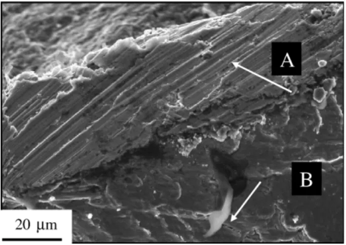
The fatigue-testing results were complemented with SEM characterization of the fracture surfaces. Fig. 6 shows the fracture surface of the nanostructured titania coating specimen that failed at σ = 355 MPa, N = 128,500 cycles. The nanos-tructured titania coating exhibits ductile tearing, feature A, a characteristic of bulk materials [19]. It is not common for thermal spray ceramic coatings to exhibit such characteristics. Ductile tearing consumes a significant amount of energy making the material “tougher”. It is also a clear indication of a coating with a relatively high elastic modulus (E).
Fig. 7 shows the fracture surface of the nanostructured titania coating specimen that failed at σ = 355 MPa,
N = 325,900 cycles. This figure clearly shows that the
HVOF-sprayed titania coating produced a uniform thin layer of compressive residual stress on the AISI 1810 steel substrate. Therefore, cracks initiated below this layer [11,20,21]. Conse-quently, the rate of fatigue damage decreased and the fatigue life increased. Hence, cracks started near the surface at inclusions and/or highly stressed locations. It is well known that thermal spray coating process imparts a residual stress in the surface layer of the coated component[22–24]. Compressive residual stresses are often deliberately induced in the surfaces of components, using a variety of surface enhancement methods, to improve fatigue life[25].
Fig. 6. Fracture surface of AISI 1018 steel specimen (failed at 128,500 cycles) coated with HVOF nanostructured titania coating. Features indicated as “A” points to ductile tearing in the coating; while “B” features are indicative of the origin of cracks.
Fig. 7. SEM fractograph of fracture surface of steel specimen coated with HVOF nanostructured titania showing a layer of compressive stress indicated by an arrow, which was formed directly under the coating.
Fig. 8a shows the fracture surface of the APS conventional titania coated specimen that failed at σ = 355 MPa, N = 73,800 cycles. The fracture surface indicates poor adhesion between the coating and the substrate. When the hard coating
layer has weak adhesion strength, then it may detach from the substrate and any residual debris would promote cracking by a wedging action of particles at the interface. It was also reported that when the coating adherence strength is weak a small ex-ternal stress or a variation in temperature will provoke coating detachment[26].
Fig. 8b shows a high magnification image of Fig. 8a and provides evidence of the crushing of the conventional titania coating at the interface.Fig. 8b reveals valuable information about the nature of deformation of these coatings. This coating clearly exhibited relatively lower elastic modulus (E) than that of the HVOF nanostructured coating.
These results are in good agreement with the previous results obtained from the crack propagation test [1]. In addition to the weak adhesion (interface bond), the conven-tional titania coating exhibited very low resistance to bending (tension or compression) deformation during the fatigue test. This material response is attributed to the low fatigue resistance exhibited by this type of coating.
3.5. Elastic modulus of the coated specimen as a system
The stress–strain curves obtained from a cantilever bending experiments are shown inFig. 9. The nanostructured titania coated specimen indicated an elastic modulus that was 23% greater than the uncoated specimen. The conventional titania coated specimen exhibited a corresponding 10% increase in the elastic modulus compared to the uncoated specimen. It has been reported that the coating spallation resistance and the stiffness of the coated component are greatly affected by the coating elastic modulus[27].
In this investigation, an attempt has been made to show the effect of the starting powder and the spray process of the titania coating on the fatigue strength and stiffness (modulus) of the coated speciment as a system (substrate + coating). This investigation did not attempt to predict or estimate the modulus of the coating separately. Instead, comparing the
Fig. 9. Stress–Strain curves of AISI 1018 steel uncoated and coated specimens. Fig. 8. (a) Fracture surface of AISI 1018 steel specimen coated with APS conventional titania coating. (b) High magnification image of (a). Small particles that are indicative of crushing of the conventional titania coating at the interface.
Fig. 10. Stress–time curves of AISI 1018 steel coated with APS conventional and HVOF nanostructured titania coatings.
fatigue strength and stiffness of steel specimens HVOF-sprayed with nanostructured titania and APS HVOF-sprayed with conventional titania.
3.6. Strain–time curves
Durability issues of thermal spray coatings under high cyclic conditions are of major concern. It has been recognized that the coating failure driving force increases, whereas the resistance decreases, with time[28].Fig. 10shows the strain– time data of AISI 1018 coated with TiO2. An initial
observation is that these coatings are in compression. Furthermore, the average strain amplitude of the HVOF-sprayed nanostructured TiO2 coating is ∼0.26 and
signifi-cantly lower than the ∼0.77 observed for the APS processed conventional TiO2. The HVOF-sprayed nanostructured TiO2
exhibited steady-state deformation during the test. The strain– time curve for the APS-sprayed conventional TiO2 has a
characteristic response. Initially, as the load was applied, the elastic strain for the APS conventional TiO2 was relatively
small. Then, after some time under constant stress, the rate of strain increased by a large degree.
The strain amplitude is an indirect measure of the stiffness and indicates the fatigue resistance of the coated specimen. Higher strain amplitude has a detrimental effect on the fatigue life of the specimen[28,29]. It is also important to note that the crack resistance is a function of the plastic behavior of the material and of its fracture characteristics.
The fatigue strength of thermally sprayed components can be considered as a combination of coating and substrate perfor-mance. A coating with a high modulus of elasticity (E) is stiffer and therefore will bear a greater load than one made from a coating with a lower E. A coating system with a compressive residual stress in the substrate will improve the fatigue strength of the substrate. These concepts are in agreement with the experimental results obtained in this paper.
4. Conclusions
The fatigue and mechanical properties of HVOF-sprayed nanostructured and APS conventional titania (TiO2) coatings
were investigated. The significant increase in the fatigue strength of the HVOF-sprayed nanostructured titania coated steel specimen was created by: a) the ability of the high elastic modulus coating to carry a relatively large portion of the load, b) the compressive residual stress imparted by the coating application process. The HVOF-sprayed coating produced a uniform layer of compressive residual stress on the AISI 1810 steel substrate. These characteristics were the result of the process of HVOF spraying. The fatigue strength results can also be correlated with the crack propagation resistance, which for the HVOF-sprayed nanostructured coating is almost 2 times higher than that of the APS conventional coating and approximately 1.6 times higher than that of the HVOF-sprayed conventional titania (according to previous findings). Therefore, the enhanced fatigue strength of the HVOF-sprayed nanos-tructured coating is caused by the combination of employing (i) a
nanostructured feedstock and (ii) the process of HVOF. The strain–time curve of AISI 1018 coated with TiO2showed lower
strain amplitude for the HVOF-sprayed nanostructured TiO2
coating compared to the APS-sprayed conventional TiO2, i.e.,
the strain amplitude of the coated component can be used as an indirect measure of the stiffness and indicates the fatigue resistance of the coated specimen. Consequently, the results obtained during this work continue to demonstrate that in order to engineer titania coatings with enhanced mechanical perfor-mance, a very viable alternative to the traditional method of spraying conventional ceramic powders by APS is the HVOF spraying of nanostructured ceramic feedstock materials. References
[1] R.S. Lima, B.R. Marple, Surf. Coat. Technol. 200 (2006) 3428. [2] C.C. Koch (Ed.), Nanostructured Materials, Processing, Properties and
Potential Applications, William Andrew Publishing, Noyes, 2002. [3] M. Gell, E.H. Jordan, Y.H. Sohn, D. Goberman, L. Shaw, T.D. Xiao, Surf.
Coat. Technol. 48 (2001) 146.
[4] G.E. Kim, J. Walker Jr., J.B. Williams Jr., Nanostructured titania coated titanium, US patent 6,835,449 B2, December 28, 2004.
[5] P. Fauchais, in: S.J. Schneider Jr. (Ed.), Engineered Materials Handbook, Ceramic and Glasses, vol. 4, ASM International, Materials Park, OH, USA, 1991, p. 202.
[6] M. Miyayama, K. Koumoto, H. Yanagida, in: S.J. Schneider Jr. (Ed.), Engineered Materials Handbook, Ceramic and Glasses, vol. 4, ASM International, Materials Park, OH, USA, 1991, p. 748.
[7] J.M. Guilemany, S. Dosta, J. Nin, J.R. Miguel, J. Therm. Spray Technol. 14 (3) (2003) 397.
[8] Anon, Standard Test Method for Measuring Abrasion Using the Dry Sand/ Rubber Wheel Apparatus, ASTM, 2004, p. G65.
[9] R.S. Lima, L. Leblanc, B.R. Marple, in: E. Lugscheider (Ed.), Nanostructured and Conventional Titania Coatings for Abrasion and Slurry-Erosion Resistance Sprayed via APS, VPS and HVOF, Proceedings of the International Thermal Spray Conference, DVS-Verlag GmbH, Basel, Switzerland, 2005.
[10] Anon, Standard Test Method for Adhesion or Cohesion Strength of Thermal Spray Coatings, ASTM, 2001, p. C633.
[11] A. Ibrahim, C.C. Berndt, J. Mater. Sci. 33 (1998) 3095.
[12] A.A. Tipton, in: C.C. Berndt, S. Sampath (Eds.), Advances in Thermal Spray Science and Technology, ASM International, Materials Park, OH, 1995, p. 463.
[13] T. Rhys-Jones, T. Cunningham, Surf. Coat. Technol. 42 (1990) 13. [14] G.R. Anstis, P. Chantikul, B.R. Lawn, D.B. Marshall, J. Am. Ceram. Soc.
64 (9) (1981) 533.
[15] Anon, Standard Practice for Conducting Force Controlled Constant Amplitude Axial Fatigue Tests of Metallic Materials, ASTM, 2004, p. E466. [16] J. Gere, S. Timoshenko, Mechanics of Materials, PWS-Kent, Boston, MA,
1990.
[17] R.S. Lima, B.R. Marple, Thermal spray coatings engineered from nanostructured ceramic agglomerated powders for structural, thermal barrier and biomedical applications: A Review, J. Therm. Spray Technol., accepted for publication.
[18] T. Tanaka, S. Nishijima, M. Ichikawa, Statistical Research on Fatigue and Fracture, vol. 2, Elsevier, 1987.
[19] A.H. Sherry, M.A. Wilkes, Int J Press Vessels Piping 82 (12) (December 2005) 905.
[20] A.A. Shaniavski, Fatigue Fract. Eng. Mater. Struct. 28 (1–2) (2005) 195. [21] G.K. Haritos, T. Nicholas, D.B. Lanning, Int. J. Fatigue 21 (1999) 643. [22] M.S.J. Hashmi, C. Pappalettere, F. Ventola, Journal of Materials
Processing Technology 75 (286) (1998) 81. 287.
[23] O.C. Brandt, in: C.C. Berndt (Ed.), Proceedings of the 8th National Thermal Spray Conference on Advances in Thermal Spray Science and Technology, Houston, ASM International, Materials Park, OH, 1995.
[24] L. Pawlowski, The Science and Engineering of Thermal Spray Technology, vol. 284, John Wiley, New York, 1995.
[25] P. Prevey, Residual Stress in Design, Process and Material Selection, ASM, Metals Park, OH, 1987, p. 11.
[26] M. Piens, H. De Deurwaerder, Prog. Org. Coat. 43 (1–3) (November 2001) 18.
[27] D. Zhu, R.A. Miller, NASA TM (2000) 210237.
[28] H. Sakamoto, Proceedings of the 8th International Fatigue Conference, Stockholm, Sweden, , 2002.
[29] C. Kanchanomai, Y. Miyashita, Y. Mutoh, Int. J. Fatigue 24 (2002) 987. 7596 A. Ibrahim et al. / Surface & Coatings Technology 201 (2007) 7589–7596

![Fig. 4 [1] shows the typical crack indentation behavior of the coatings produced in this study](https://thumb-eu.123doks.com/thumbv2/123doknet/14173217.474880/5.892.67.410.522.1052/shows-typical-crack-indentation-behavior-coatings-produced-study.webp)